1999 SUBARU LEGACY battery location
[x] Cancel search: battery locationPage 661 of 1456
1. Propeller Shaft
A: ON-CAR SERVICE
1) Joints and connections
Check for any looseness of yoke flange connect-
ing bolts and center bearing retaining bolts.
2) Splines and bearing locations
Turn propeller shaft by hand to see if abnormal free
play exists at splines. Also move yokes to see if
abnormal free play exists at spiders and bearings.
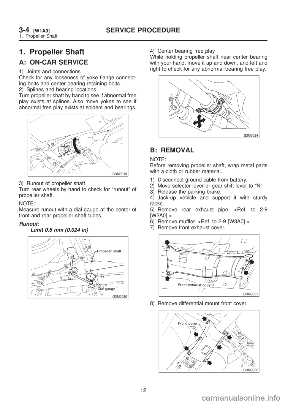
G3M0019
3) Runout of propeller shaft
Turn rear wheels by hand to check for ªrunoutº of
propeller shaft.
NOTE:
Measure runout with a dial gauge at the center of
front and rear propeller shaft tubes.
Runout:
Limit 0.6 mm (0.024 in)
G3M0020
4) Center bearing free play
While holding propeller shaft near center bearing
with your hand, move it up and down, and left and
right to check for any abnormal bearing free play.
S3M0024
B: REMOVAL
NOTE:
Before removing propeller shaft, wrap metal parts
with a cloth or rubber material.
1) Disconnect ground cable from battery.
2) Move selector lever or gear shift lever to ªNº.
3) Release the parking brake.
4) Jack-up vehicle and support it with sturdy
racks.
5) Remove rear exhaust pipe.
6) Remove muffler.
7) Remove front exhaust cover.
G3M0021
8) Remove differential mount front cover.
G3M0022
12
3-4[W1A0]SERVICE PROCEDURE
1. Propeller Shaft
Page 726 of 1456
B: INSPECTION
1) Check bushing for cracks, fatigue or damage.
2) Check stabilizer link for deformities, cracks, or
damage, and bushing for protrusions from the hole
of stabilizer link and its play.
C: INSTALLATION
1) To install, reverse the removal procedure.
NOTE:
IInstall bushing (on front crossmember side)
while aligning it with paint mark on stabilizer.
IEnsure that bushing and stabilizer have the
same identification colors when installing.
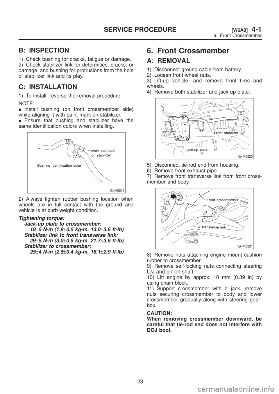
G4M0519
2) Always tighten rubber bushing location when
wheels are in full contact with the ground and
vehicle is at curb weight condition.
Tightening torque:
Jack-up plate to crossmember:
18
±5 N´m (1.8±0.5 kg-m, 13.0±3.6 ft-lb)
Stabilizer link to front transverse link:
29
±5 N´m (3.0±0.5 kg-m, 21.7±3.6 ft-lb)
Stabilizer to crossmember:
25
±4 N´m (2.5±0.4 kg-m, 18.1±2.9 ft-lb)
6. Front Crossmember
A: REMOVAL
1) Disconnect ground cable from battery.
2) Loosen front wheel nuts.
3) Lift-up vehicle, and remove front tires and
wheels.
4) Remove both stabilizer and jack-up plate.
G4M0520
5) Disconnect tie-rod end from housing.
6) Remove front exhaust pipe.
7) Remove front transverse link from front cross-
member and body.
G4M0521
8) Remove nuts attaching engine mount cushion
rubber to crossmember.
9) Remove self-locking nuts connecting steering
U/J and pinion shaft.
10) Lift engine by approx. 10 mm (0.39 in) by
using chain block.
11) Support crossmember with a jack, remove
nuts securing crossmember to body and lower
crossmember gradually along with steering gear-
box.
CAUTION:
When removing crossmember downward, be
careful that tie-rod end does not interfere with
DOJ boot.
23
[W6A0]4-1SERVICE PROCEDURE
6. Front Crossmember
Page 727 of 1456
B: INSPECTION
1) Check bushing for cracks, fatigue or damage.
2) Check stabilizer link for deformities, cracks, or
damage, and bushing for protrusions from the hole
of stabilizer link and its play.
C: INSTALLATION
1) To install, reverse the removal procedure.
NOTE:
IInstall bushing (on front crossmember side)
while aligning it with paint mark on stabilizer.
IEnsure that bushing and stabilizer have the
same identification colors when installing.
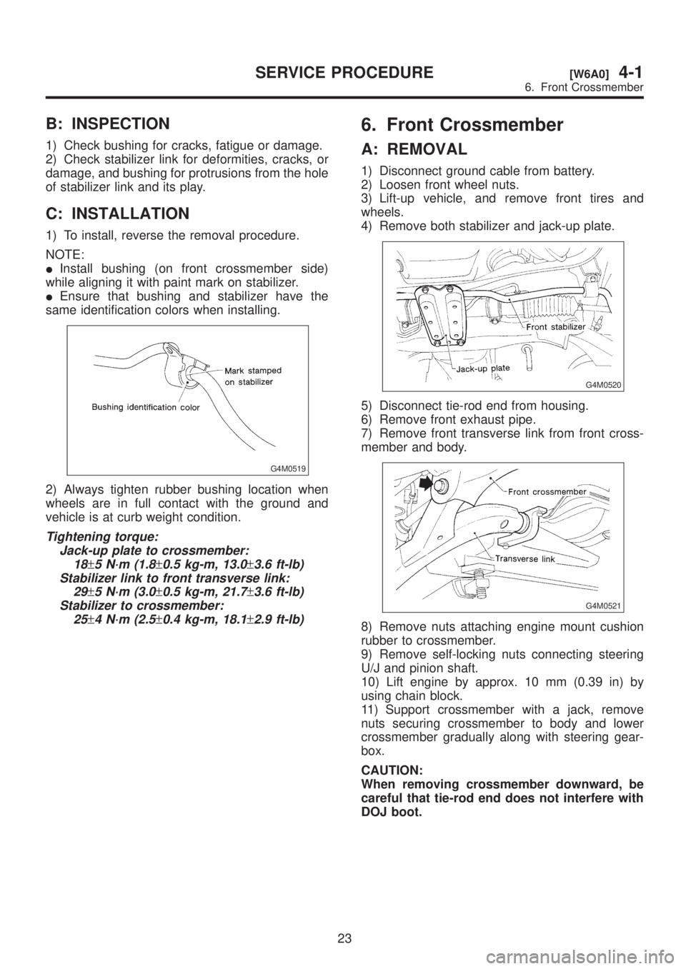
G4M0519
2) Always tighten rubber bushing location when
wheels are in full contact with the ground and
vehicle is at curb weight condition.
Tightening torque:
Jack-up plate to crossmember:
18
±5 N´m (1.8±0.5 kg-m, 13.0±3.6 ft-lb)
Stabilizer link to front transverse link:
29
±5 N´m (3.0±0.5 kg-m, 21.7±3.6 ft-lb)
Stabilizer to crossmember:
25
±4 N´m (2.5±0.4 kg-m, 18.1±2.9 ft-lb)
6. Front Crossmember
A: REMOVAL
1) Disconnect ground cable from battery.
2) Loosen front wheel nuts.
3) Lift-up vehicle, and remove front tires and
wheels.
4) Remove both stabilizer and jack-up plate.
G4M0520
5) Disconnect tie-rod end from housing.
6) Remove front exhaust pipe.
7) Remove front transverse link from front cross-
member and body.
G4M0521
8) Remove nuts attaching engine mount cushion
rubber to crossmember.
9) Remove self-locking nuts connecting steering
U/J and pinion shaft.
10) Lift engine by approx. 10 mm (0.39 in) by
using chain block.
11) Support crossmember with a jack, remove
nuts securing crossmember to body and lower
crossmember gradually along with steering gear-
box.
CAUTION:
When removing crossmember downward, be
careful that tie-rod end does not interfere with
DOJ boot.
23
[W6A0]4-1SERVICE PROCEDURE
6. Front Crossmember
Page 870 of 1456
F: CLEARANCE TABLE
CAUTION:
This table lists various clearances that must be
correctly adjusted to ensure normal vehicle
driving without interfering noise, or any other
faults.
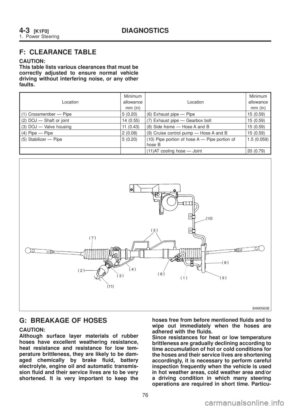
LocationMinimum
allowance
mm (in)LocationMinimum
allowance
mm (in)
(1) Crossmember Ð Pipe 5 (0.20) (6) Exhaust pipe Ð Pipe 15 (0.59)
(2) DOJ Ð Shaft or joint 14 (0.55) (7) Exhaust pipe Ð Gearbox bolt 15 (0.59)
(3) DOJ Ð Valve housing 11 (0.43) (8) Side frame Ð Hose A and B 15 (0.59)
(4) Pipe Ð Pipe 2 (0.08) (9) Cruise control pump Ð Hose A and B 15 (0.59)
(5) Stabilizer Ð Pipe 5 (0.20) (10) Pipe portion of hose A Ð Pipe portion of
hose B1.5 (0.059)
(11)AT cooling hose Ð Joint 20 (0.79)
B4M0565B
G: BREAKAGE OF HOSES
CAUTION:
Although surface layer materials of rubber
hoses have excellent weathering resistance,
heat resistance and resistance for low tem-
perature brittleness, they are likely to be dam-
aged chemically by brake fluid, battery
electrolyte, engine oil and automatic transmis-
sion fluid and their service lives are to be very
shortened. It is very important to keep thehoses free from before mentioned fluids and to
wipe out immediately when the hoses are
adhered with the fluids.
Since resistances for heat or low temperature
brittleness are gradually declining according to
time accumulation of hot or cold conditions for
the hoses and their service lives are shortening
accordingly, it is necessary to perform careful
inspection frequently when the vehicle is used
in hot weather areas, cold weather area and/or
a driving condition in which many steering
operations are required in short time. Particu-
76
4-3[K1F0]DIAGNOSTICS
1. Power Steering
Page 1284 of 1456
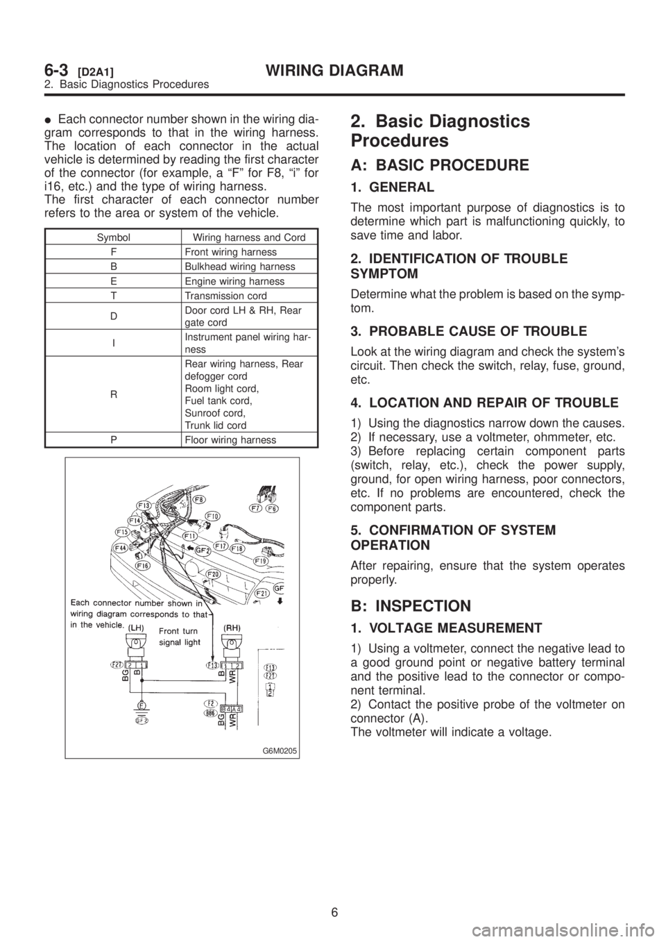
IEach connector number shown in the wiring dia-
gram corresponds to that in the wiring harness.
The location of each connector in the actual
vehicle is determined by reading the first character
of the connector (for example, a ªFº for F8, ªiº for
i16, etc.) and the type of wiring harness.
The first character of each connector number
refers to the area or system of the vehicle.
Symbol Wiring harness and Cord
F Front wiring harness
B Bulkhead wiring harness
E Engine wiring harness
T Transmission cord
DDoor cord LH & RH, Rear
gate cord
IInstrument panel wiring har-
ness
RRear wiring harness, Rear
defogger cord
Room light cord,
Fuel tank cord,
Sunroof cord,
Trunk lid cord
P Floor wiring harness
G6M0205
2. Basic Diagnostics
Procedures
A: BASIC PROCEDURE
1. GENERAL
The most important purpose of diagnostics is to
determine which part is malfunctioning quickly, to
save time and labor.
2. IDENTIFICATION OF TROUBLE
SYMPTOM
Determine what the problem is based on the symp-
tom.
3. PROBABLE CAUSE OF TROUBLE
Look at the wiring diagram and check the system's
circuit. Then check the switch, relay, fuse, ground,
etc.
4. LOCATION AND REPAIR OF TROUBLE
1) Using the diagnostics narrow down the causes.
2) If necessary, use a voltmeter, ohmmeter, etc.
3) Before replacing certain component parts
(switch, relay, etc.), check the power supply,
ground, for open wiring harness, poor connectors,
etc. If no problems are encountered, check the
component parts.
5. CONFIRMATION OF SYSTEM
OPERATION
After repairing, ensure that the system operates
properly.
B: INSPECTION
1. VOLTAGE MEASUREMENT
1) Using a voltmeter, connect the negative lead to
a good ground point or negative battery terminal
and the positive lead to the connector or compo-
nent terminal.
2) Contact the positive probe of the voltmeter on
connector (A).
The voltmeter will indicate a voltage.
6
6-3[D2A1]WIRING DIAGRAM
2. Basic Diagnostics Procedures
Page 1285 of 1456
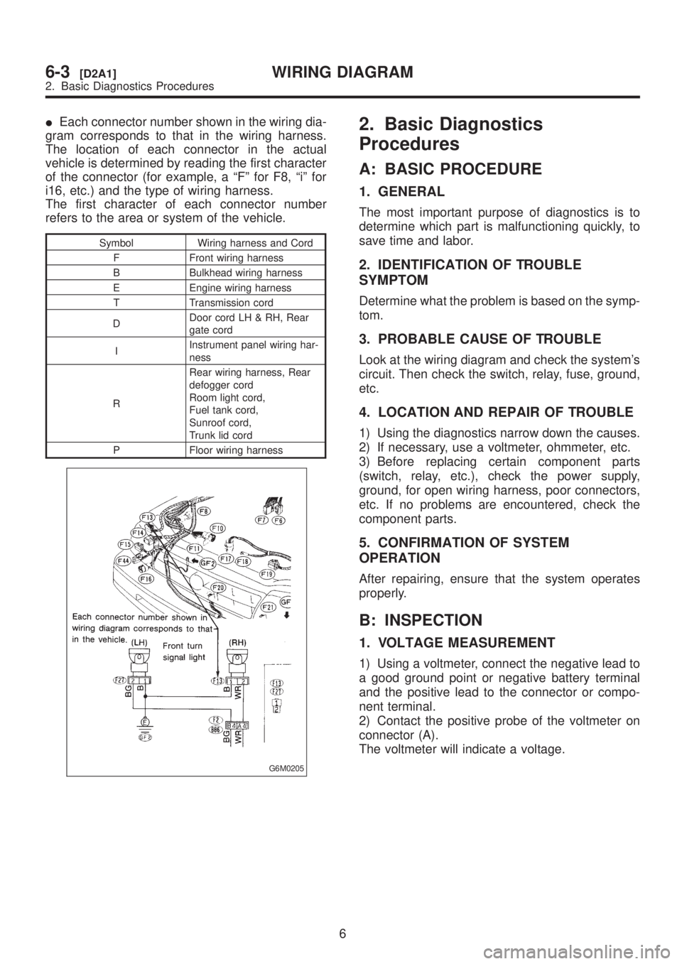
IEach connector number shown in the wiring dia-
gram corresponds to that in the wiring harness.
The location of each connector in the actual
vehicle is determined by reading the first character
of the connector (for example, a ªFº for F8, ªiº for
i16, etc.) and the type of wiring harness.
The first character of each connector number
refers to the area or system of the vehicle.
Symbol Wiring harness and Cord
F Front wiring harness
B Bulkhead wiring harness
E Engine wiring harness
T Transmission cord
DDoor cord LH & RH, Rear
gate cord
IInstrument panel wiring har-
ness
RRear wiring harness, Rear
defogger cord
Room light cord,
Fuel tank cord,
Sunroof cord,
Trunk lid cord
P Floor wiring harness
G6M0205
2. Basic Diagnostics
Procedures
A: BASIC PROCEDURE
1. GENERAL
The most important purpose of diagnostics is to
determine which part is malfunctioning quickly, to
save time and labor.
2. IDENTIFICATION OF TROUBLE
SYMPTOM
Determine what the problem is based on the symp-
tom.
3. PROBABLE CAUSE OF TROUBLE
Look at the wiring diagram and check the system's
circuit. Then check the switch, relay, fuse, ground,
etc.
4. LOCATION AND REPAIR OF TROUBLE
1) Using the diagnostics narrow down the causes.
2) If necessary, use a voltmeter, ohmmeter, etc.
3) Before replacing certain component parts
(switch, relay, etc.), check the power supply,
ground, for open wiring harness, poor connectors,
etc. If no problems are encountered, check the
component parts.
5. CONFIRMATION OF SYSTEM
OPERATION
After repairing, ensure that the system operates
properly.
B: INSPECTION
1. VOLTAGE MEASUREMENT
1) Using a voltmeter, connect the negative lead to
a good ground point or negative battery terminal
and the positive lead to the connector or compo-
nent terminal.
2) Contact the positive probe of the voltmeter on
connector (A).
The voltmeter will indicate a voltage.
6
6-3[D2A1]WIRING DIAGRAM
2. Basic Diagnostics Procedures
Page 1291 of 1456
F: CONNECTOR SKETCH
IEach connector sketch clearly identifies the
shape and color of a connector as well as terminal
locations. Non-colored connectors are indicated in
natural color.
IWhen more than two types of connector number
are indicated in a connector sketch, it means that
the same type connectors are used.
G: GROUND
Each grounding point can be located easily by
referring to the corresponding wiring harness.
H: DIODE
A symbol is used to indicate a diode.
I: WIRE TRACING ON EXTENDED
WIRING DIAGRAMS
For a wiring diagram extending over at least two
pages, a symbol (consisting of the same charac-
ters with arrows), as shown below, facilitates wire
tracing from one page to the next.
A¨A, B¨B
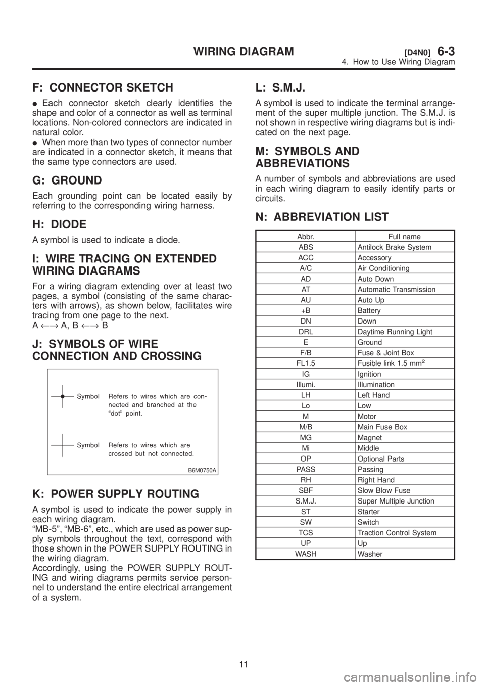
J: SYMBOLS OF WIRE
CONNECTION AND CROSSING
B6M0750A
K: POWER SUPPLY ROUTING
A symbol is used to indicate the power supply in
each wiring diagram.
ªMB-5º, ªMB-6º, etc., which are used as power sup-
ply symbols throughout the text, correspond with
those shown in the POWER SUPPLY ROUTING in
the wiring diagram.
Accordingly, using the POWER SUPPLY ROUT-
ING and wiring diagrams permits service person-
nel to understand the entire electrical arrangement
of a system.
L: S.M.J.
A symbol is used to indicate the terminal arrange-
ment of the super multiple junction. The S.M.J. is
not shown in respective wiring diagrams but is indi-
cated on the next page.
M: SYMBOLS AND
ABBREVIATIONS
A number of symbols and abbreviations are used
in each wiring diagram to easily identify parts or
circuits.
N: ABBREVIATION LIST
Abbr. Full name
ABS Antilock Brake System
ACC Accessory
A/C Air Conditioning
AD Auto Down
AT Automatic Transmission
AU Auto Up
+B Battery
DN Down
DRL Daytime Running Light
E Ground
F/B Fuse & Joint Box
FL1.5 Fusible link 1.5 mm
2
IG Ignition
Illumi. Illumination
LH Left Hand
Lo Low
M Motor
M/B Main Fuse Box
MG Magnet
Mi Middle
OP Optional Parts
PASS Passing
RH Right Hand
SBF Slow Blow Fuse
S.M.J. Super Multiple Junction
ST Starter
SW Switch
TCS Traction Control System
UP Up
WASH Washer
11
[D4N0]6-3WIRING DIAGRAM
4. How to Use Wiring Diagram