1999 SUBARU LEGACY inflation pressure
[x] Cancel search: inflation pressurePage 702 of 1456
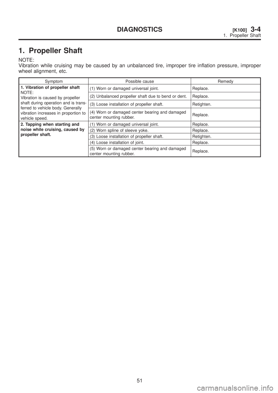
1. Propeller Shaft
NOTE:
Vibration while cruising may be caused by an unbalanced tire, improper tire inflation pressure, improper
wheel alignment, etc.
Symptom Possible cause Remedy
1. Vibration of propeller shaft
NOTE:
Vibration is caused by propeller
shaft during operation and is trans-
ferred to vehicle body. Generally
vibration increases in proportion to
vehicle speed.(1) Worn or damaged universal joint. Replace.
(2) Unbalanced propeller shaft due to bend or dent. Replace.
(3) Loose installation of propeller shaft. Retighten.
(4) Worn or damaged center bearing and damaged
center mounting rubber.Replace.
2. Tapping when starting and
noise while cruising, caused by
propeller shaft.(1) Worn or damaged universal joint. Replace.
(2) Worn spline of sleeve yoke. Replace.
(3) Loose installation of propeller shaft. Retighten.
(4) Loose installation of joint. Replace.
(5) Worn or damaged center bearing and damaged
center mounting rubber.Replace.
51
[K100]3-4DIAGNOSTICS
1. Propeller Shaft
Page 744 of 1456
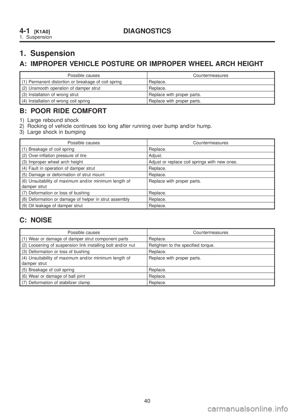
1. Suspension
A: IMPROPER VEHICLE POSTURE OR IMPROPER WHEEL ARCH HEIGHT
Possible causes Countermeasures
(1) Permanent distortion or breakage of coil spring Replace.
(2) Unsmooth operation of damper strut Replace.
(3) Installation of wrong strut Replace with proper parts.
(4) Installation of wrong coil spring Replace with proper parts.
B: POOR RIDE COMFORT
1) Large rebound shock
2) Rocking of vehicle continues too long after running over bump and/or hump.
3) Large shock in bumping
Possible causes Countermeasures
(1) Breakage of coil spring Replace.
(2) Over-inflation pressure of tire Adjust.
(3) Improper wheel arch height Adjust or replace coil springs with new ones.
(4) Fault in operation of damper strut Replace.
(5) Damage or deformation of strut mount Replace.
(6) Unsuitability of maximum and/or minimum length of
damper strutReplace with proper parts.
(7) Deformation or loss of bushing Replace.
(8) Deformation or damage of helper in strut assembly Replace.
(9) Oil leakage of damper strut Replace.
C: NOISE
Possible causes Countermeasures
(1) Wear or damage of damper strut component parts Replace.
(2) Loosening of suspension link installing bolt and/or nut Retighten to the specified torque.
(3) Deformation or loss of bushing Replace.
(4) Unsuitability of maximum and/or minimum length of
damper strutReplace with proper parts.
(5) Breakage of coil spring Replace.
(6) Wear or damage of ball joint Replace.
(7) Deformation of stabilizer clamp Replace.
40
4-1[K1A0]DIAGNOSTICS
1. Suspension
Page 745 of 1456
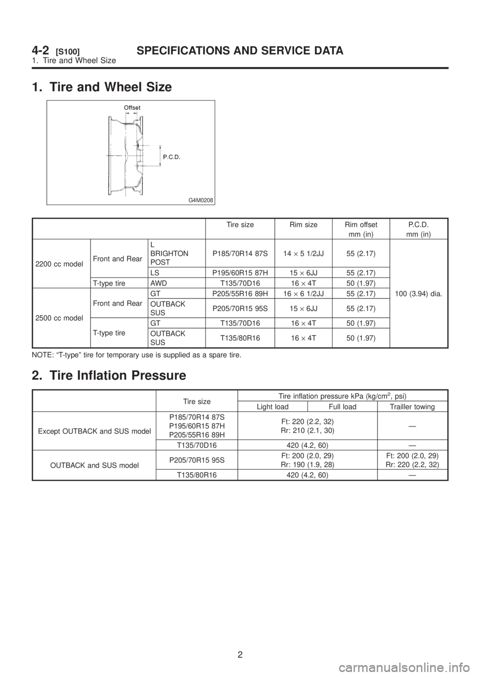
1. Tire and Wheel Size
G4M0208
Tire size Rim size Rim offset
mm (in)P.C.D.
mm (in)
2200 cc modelFront and RearL
BRIGHTON
POSTP185/70R14 87S 14´5 1/2JJ 55 (2.17)
100 (3.94) dia. LS P195/60R15 87H 15´6JJ 55 (2.17)
T-type tire AWD T135/70D16 16´4T 50 (1.97)
2500 cc modelFront and RearGT P205/55R16 89H 16´6 1/2JJ 55 (2.17)
OUTBACK
SUSP205/70R15 95S 15´6JJ 55 (2.17)
T-type tireGT T135/70D16 16´4T 50 (1.97)
OUTBACK
SUST135/80R16 16´4T 50 (1.97)
NOTE: ªT-typeº tire for temporary use is supplied as a spare tire.
2. Tire Inflation Pressure
Tire sizeTire inflation pressure kPa (kg/cm
2, psi)
Light load Full load Trailler towing
Except OUTBACK and SUS modelP185/70R14 87S
P195/60R15 87H
P205/55R16 89HFt: 220 (2.2, 32)
Rr: 210 (2.1, 30)Ð
T135/70D16 420 (4.2, 60) Ð
OUTBACK and SUS modelP205/70R15 95SFt: 200 (2.0, 29)
Rr: 190 (1.9, 28)Ft: 200 (2.0, 29)
Rr: 220 (2.2, 32)
T135/80R16 420 (4.2, 60) Ð
2
4-2[S100]SPECIFICATIONS AND SERVICE DATA
1. Tire and Wheel Size
Page 746 of 1456
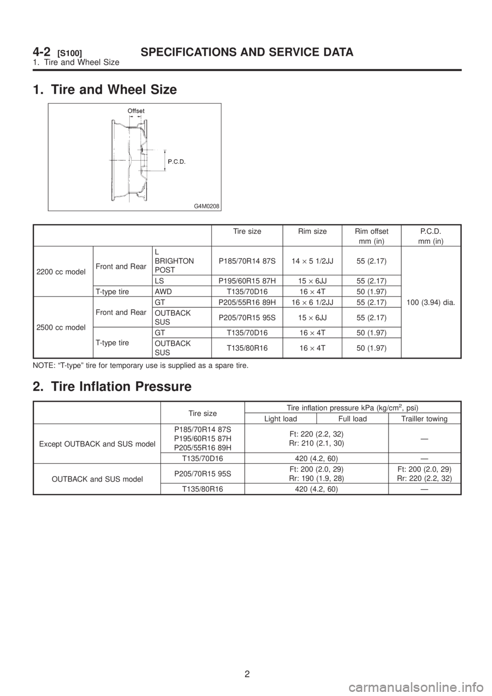
1. Tire and Wheel Size
G4M0208
Tire size Rim size Rim offset
mm (in)P.C.D.
mm (in)
2200 cc modelFront and RearL
BRIGHTON
POSTP185/70R14 87S 14´5 1/2JJ 55 (2.17)
100 (3.94) dia. LS P195/60R15 87H 15´6JJ 55 (2.17)
T-type tire AWD T135/70D16 16´4T 50 (1.97)
2500 cc modelFront and RearGT P205/55R16 89H 16´6 1/2JJ 55 (2.17)
OUTBACK
SUSP205/70R15 95S 15´6JJ 55 (2.17)
T-type tireGT T135/70D16 16´4T 50 (1.97)
OUTBACK
SUST135/80R16 16´4T 50 (1.97)
NOTE: ªT-typeº tire for temporary use is supplied as a spare tire.
2. Tire Inflation Pressure
Tire sizeTire inflation pressure kPa (kg/cm
2, psi)
Light load Full load Trailler towing
Except OUTBACK and SUS modelP185/70R14 87S
P195/60R15 87H
P205/55R16 89HFt: 220 (2.2, 32)
Rr: 210 (2.1, 30)Ð
T135/70D16 420 (4.2, 60) Ð
OUTBACK and SUS modelP205/70R15 95SFt: 200 (2.0, 29)
Rr: 190 (1.9, 28)Ft: 200 (2.0, 29)
Rr: 220 (2.2, 32)
T135/80R16 420 (4.2, 60) Ð
2
4-2[S100]SPECIFICATIONS AND SERVICE DATA
1. Tire and Wheel Size
Page 792 of 1456
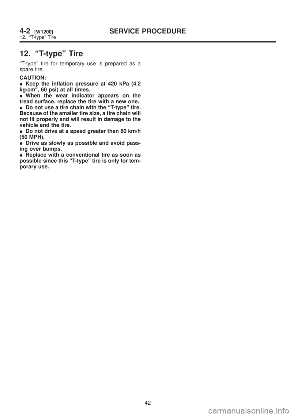
12. ªT-typeº Tire
ªT-typeº tire for temporary use is prepared as a
spare tire.
CAUTION:
IKeep the inflation pressure at 420 kPa (4.2
kg/cm
2, 60 psi) at all times.
IWhen the wear indicator appears on the
tread surface, replace the tire with a new one.
IDo not use a tire chain with the ªT-typeº tire.
Because of the smaller tire size, a tire chain will
not fit properly and will result in damage to the
vehicle and the tire.
IDo not drive at a speed greater than 80 km/h
(50 MPH).
IDrive as slowly as possible and avoid pass-
ing over bumps.
IReplace with a conventional tire as soon as
possible since this ªT-typeº tire is only for tem-
porary use.
42
4-2[W1200]SERVICE PROCEDURE
12. ªT-typeº Tire
Page 943 of 1456
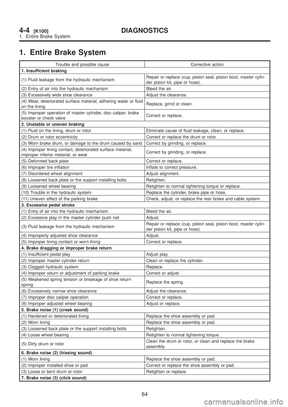
1. Entire Brake System
Trouble and possible cause Corrective action
1. Insufficient braking
(1) Fluid leakage from the hydraulic mechanismRepair or replace (cup, piston seal, piston boot, master cylin-
der piston kit, pipe or hose).
(2) Entry of air into the hydraulic mechanism Bleed the air.
(3) Excessively wide shoe clearance Adjust the clearance.
(4) Wear, deteriorated surface material, adhering water or fluid
on the liningReplace, grind or clean.
(5) Improper operation of master cylinder, disc caliper, brake
booster or check valveCorrect or replace.
2. Unstable or uneven braking
(1) Fluid on the lining, drum or rotor Eliminate cause of fluid leakage, clean, or replace.
(2) Drum or rotor eccentricity Correct or replace the drum or rotor.
(3) Worn brake drum, or damage to the drum caused by sand Correct by grinding, or replace.
(4) Improper lining contact, deteriorated surface material,
improper inferior material, or wearCorrect by grinding, or replace.
(5) Deformed back plate Correct or replace.
(6) Improper tire inflation Inflate to correct pressure.
(7) Disordered wheel alignment Adjust alignment.
(8) Loosened back plate or the support installing bolts Retighten.
(9) Loosened wheel bearing Retighten to normal tightening torque or replace.
(10) Trouble in the hydraulic system Replace the cylinder, brake pipe or hose.
(11) Uneven effect of the parking brake Check, adjust, or replace the rear brake and cable system.
3. Excessive pedal stroke
(1) Entry of air into the hydraulic mechanism Bleed the air.
(2) Excessive play in the master cylinder push rod Adjust.
(3) Fluid leakage from the hydraulic mechanismRepair or replace (cup, piston seal, piston boot, master cylin-
der piston kit, pipe or hose).
(4) Improperly adjusted shoe clearance Adjust.
(5) Improper lining contact or worn lining Correct or replace.
4. Brake dragging or improper brake return
(1) Insufficient pedal play Adjust play.
(2) Improper master cylinder return Clean or replace the cylinder.
(3) Clogged hydraulic system Replace.
(4) Improper return or adjustment of parking brake Correct or adjust.
(5) Weakened spring tension or breakage of shoe return
springReplace the spring.
(6) Excessively narrow shoe clearance Adjust the clearance.
(7) Improper disc caliper operation Correct or replace.
(8) Improper adjusted wheel bearing Adjust or replace.
5. Brake noise (1) (creak sound)
(1) Hardened or deteriorated lining Replace the shoe assembly or pad.
(2) Worn lining Replace the shoe assembly or pad.
(3) Loosened back plate or the support installing bolts Retighten.
(4) Loose wheel bearing Retighten to normal tightening torque.
(5) Dirty drum or rotorClean the drum or rotor, or clean and replace the brake
assembly.
6. Brake noise (2) (hissing sound)
(1) Worn lining Replace the shoe assembly or pad.
(2) Improper installed shoe or pad Correct or replace the shoe assembly or pad.
(3) Loose or bent drum or rotor Retighten or replace.
7. Brake noise (3) (click sound)
64
4-4[K100]DIAGNOSTICS
1. Entire Brake System
Page 1231 of 1456
4. Headlight
A: ADJUSTMENT
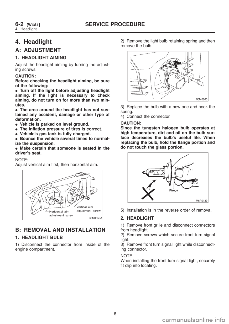
1. HEADLIGHT AIMING
Adjust the headlight aiming by turning the adjust-
ing screws.
CAUTION:
Before checking the headlight aiming, be sure
of the following:
ITurn off the light before adjusting headlight
aiming. If the light is necessary to check
aiming, do not turn on for more than two min-
utes.
IThe area around the headlight has not sus-
tained any accident, damage or other type of
deformation.
IVehicle is parked on level ground.
IThe inflation pressure of tires is correct.
IVehicle's gas tank is fully charged.
IBounce the vehicle several times to normal-
ize the suspension.
IMake certain that someone is seated in the
driver's seat.
NOTE:
Adjust vertical aim first, then horizontal aim.
B6M0859A
B: REMOVAL AND INSTALLATION
1. HEADLIGHT BULB
1) Disconnect the connector from inside of the
engine compartment.2) Remove the light bulb retaining spring and then
remove the bulb.
B6M0860
3) Replace the bulb with a new one and hook the
spring.
4) Connect the connector.
CAUTION:
Since the tungsten halogen bulb operates at
high temperature, dirt and oil on the bulb sur-
face decreases the bulb's useful life. When
replacing the bulb, hold the flange portion and
do not touch the glass portion.
M6A0139
5) Installation is in the reverse order of removal.
2. HEADLIGHT
1) Remove front grille and disconnect connectors
from headlight.
2) Remove screws which secure front turn signal
light.
3) Remove front turn signal light while disconnect-
ing connector.
NOTE:
When installing the front turn signal light, securely
fit clip into locating.
6
6-2[W4A1]SERVICE PROCEDURE
4. Headlight