1999 SUBARU LEGACY battery replacement
[x] Cancel search: battery replacementPage 349 of 1456

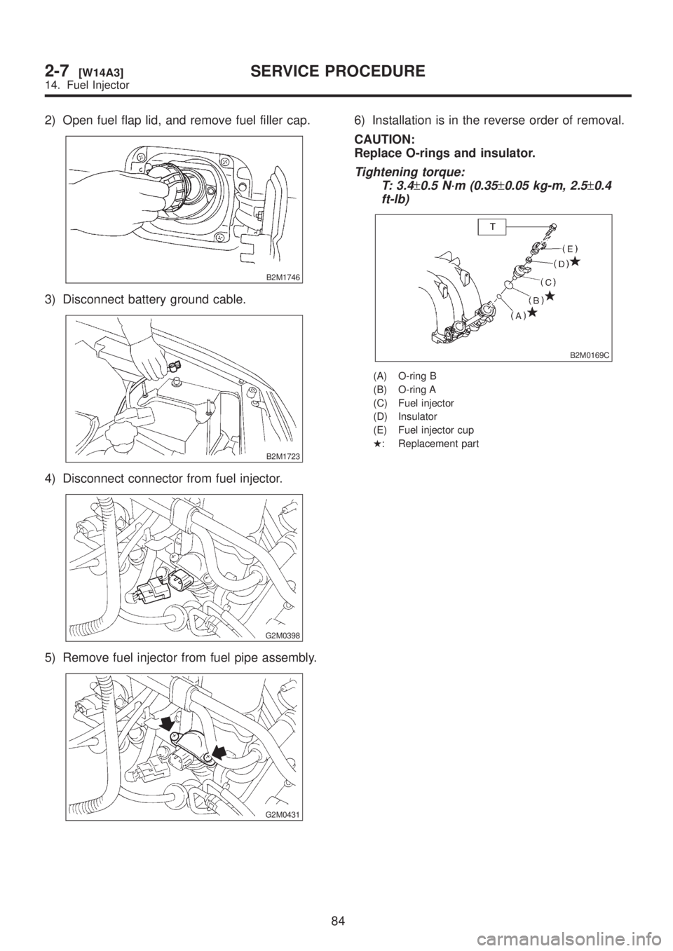
2) Open fuel flap lid, and remove fuel filler cap.
B2M1746
3) Disconnect battery ground cable.
B2M1723
4) Disconnect connector from fuel injector.
G2M0398
5) Remove fuel injector from fuel pipe assembly.
G2M0431
6) Installation is in the reverse order of removal.
CAUTION:
Replace O-rings and insulator.
Tightening torque:
T: 3.4
±0.5 N´m (0.35±0.05 kg-m, 2.5±0.4
ft-lb)
B2M0169C
(A) O-ring B
(B) O-ring A
(C) Fuel injector
(D) Insulator
(E) Fuel injector cup
H: Replacement part
84
2-7[W14A3]SERVICE PROCEDURE
14. Fuel Injector
Page 782 of 1456

4. Replacement of Front SFJ,
DOJ and BJ Boots
A: REMOVAL
1) Disconnect ground cable from battery.
2) Jack-up vehicle, support it with safety stands
(rigid racks), and remove front wheel cap and
wheels.
NOTE:
Do not remove axle nut.
3) Remove stabilizer link.
4) Disconnect transverse link from housing.
5) Remove spring pin which secures transmission
spindle to DOJ/SFJ.
CAUTION:
Use a new spring pin.
G4M0279
6) Remove SFJ, DOJ and BJ boots from drive
shaft.
B: INSTALLATION
1) Install SFJ, DOJ and BJ boots to drive shaft.
2) Install DOJ/SFJ on transmission spindle and
drive spring pin into place.
CAUTION:
Always use a new spring pin.
G4M0279
3) Connect transverse link to housing.
4) Install stabilizer link.
5. Replacement of Rear DOJ
and BJ Boots
A: REMOVAL
1) Disconnect ground cable from battery.
2) Lift-up vehicle, and remove rear wheel cap and
wheels.
NOTE:
Axle nut need not be removed.
3) Remove ABS sensor clamps and parking brake
cable bracket.
4) Disconnect stabilizer link from lateral link.
5) Remove bolts which secure lateral link assem-
bly to rear housing.
6) Remove bolts which secure trailing link assem-
bly to rear housing.
7) Remove crossmember reinforcement lower
from crossmember (4 door model only).
8) Remove DOJ from rear differential using ST.
(Except 2200 cc AT vehicles)
ST 28099PA100 DRIVE SHAFT REMOVER
CAUTION:
Do not remove circlip attached to inside of dif-
ferential.
G4M0994
CAUTION:
Be careful not to damage side bearing retainer.
Always use bolt as shown in figure, as support-
ing point for ST during removal.
ST 28099PA100 DRIVE SHAFT REMOVER
G4M0995
36
4-2[W4A0]SERVICE PROCEDURE
4. Replacement of Front SFJ, DOJ and BJ Boots
Page 783 of 1456

4. Replacement of Front SFJ,
DOJ and BJ Boots
A: REMOVAL
1) Disconnect ground cable from battery.
2) Jack-up vehicle, support it with safety stands
(rigid racks), and remove front wheel cap and
wheels.
NOTE:
Do not remove axle nut.
3) Remove stabilizer link.
4) Disconnect transverse link from housing.
5) Remove spring pin which secures transmission
spindle to DOJ/SFJ.
CAUTION:
Use a new spring pin.
G4M0279
6) Remove SFJ, DOJ and BJ boots from drive
shaft.
B: INSTALLATION
1) Install SFJ, DOJ and BJ boots to drive shaft.
2) Install DOJ/SFJ on transmission spindle and
drive spring pin into place.
CAUTION:
Always use a new spring pin.
G4M0279
3) Connect transverse link to housing.
4) Install stabilizer link.
5. Replacement of Rear DOJ
and BJ Boots
A: REMOVAL
1) Disconnect ground cable from battery.
2) Lift-up vehicle, and remove rear wheel cap and
wheels.
NOTE:
Axle nut need not be removed.
3) Remove ABS sensor clamps and parking brake
cable bracket.
4) Disconnect stabilizer link from lateral link.
5) Remove bolts which secure lateral link assem-
bly to rear housing.
6) Remove bolts which secure trailing link assem-
bly to rear housing.
7) Remove crossmember reinforcement lower
from crossmember (4 door model only).
8) Remove DOJ from rear differential using ST.
(Except 2200 cc AT vehicles)
ST 28099PA100 DRIVE SHAFT REMOVER
CAUTION:
Do not remove circlip attached to inside of dif-
ferential.
G4M0994
CAUTION:
Be careful not to damage side bearing retainer.
Always use bolt as shown in figure, as support-
ing point for ST during removal.
ST 28099PA100 DRIVE SHAFT REMOVER
G4M0995
36
4-2[W4A0]SERVICE PROCEDURE
4. Replacement of Front SFJ, DOJ and BJ Boots
Page 1229 of 1456

any other metallic portion of the vehicle
because a short circuit will be caused.
1) External parts:
Check for the existence of dirt or cracks on the
battery case, top cover, vent plugs, and terminal
posts. If necessary, clean with water and wipe with
a dry cloth. Apply a thin coat of grease on the ter-
minal posts to prevent corrosion.
2) Electrolyte level:
Check the electrolyte level in each cell. If the level
is below MIN LEVEL, bring the level to MAX
LEVEL by pouring distilled water into the battery
cell. Do not fill beyond MAX LEVEL.
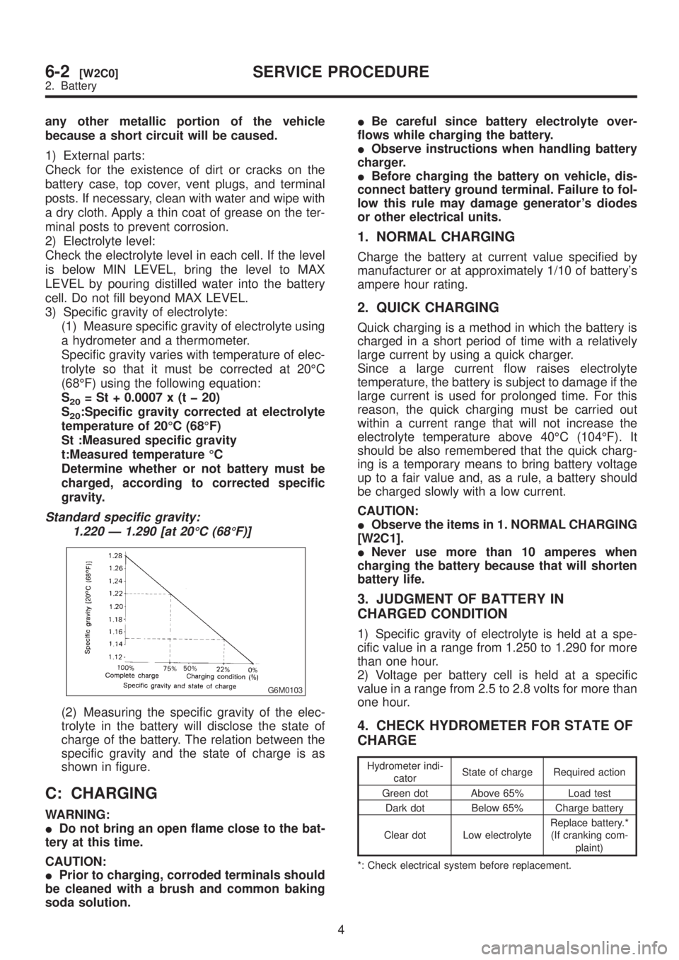
3) Specific gravity of electrolyte:
(1) Measure specific gravity of electrolyte using
a hydrometer and a thermometer.
Specific gravity varies with temperature of elec-
trolyte so that it must be corrected at 20ÉC
(68ÉF) using the following equation:
S
20= St + 0.0007 x (t þ 20)
S
20:Specific gravity corrected at electrolyte
temperature of 20ÉC (68ÉF)
St :Measured specific gravity
t:Measured temperature ÉC
Determine whether or not battery must be
charged, according to corrected specific
gravity.
Standard specific gravity:
1.220 Ð 1.290 [at 20ÉC (68ÉF)]
G6M0103
(2) Measuring the specific gravity of the elec-
trolyte in the battery will disclose the state of
charge of the battery. The relation between the
specific gravity and the state of charge is as
shown in figure.
C: CHARGING
WARNING:
IDo not bring an open flame close to the bat-
tery at this time.
CAUTION:
IPrior to charging, corroded terminals should
be cleaned with a brush and common baking
soda solution.IBe careful since battery electrolyte over-
flows while charging the battery.
IObserve instructions when handling battery
charger.
IBefore charging the battery on vehicle, dis-
connect battery ground terminal. Failure to fol-
low this rule may damage generator's diodes
or other electrical units.
1. NORMAL CHARGING
Charge the battery at current value specified by
manufacturer or at approximately 1/10 of battery's
ampere hour rating.
2. QUICK CHARGING
Quick charging is a method in which the battery is
charged in a short period of time with a relatively
large current by using a quick charger.
Since a large current flow raises electrolyte
temperature, the battery is subject to damage if the
large current is used for prolonged time. For this
reason, the quick charging must be carried out
within a current range that will not increase the
electrolyte temperature above 40ÉC (104ÉF). It
should be also remembered that the quick charg-
ing is a temporary means to bring battery voltage
up to a fair value and, as a rule, a battery should
be charged slowly with a low current.
CAUTION:
IObserve the items in 1. NORMAL CHARGING
[W2C1].
INever use more than 10 amperes when
charging the battery because that will shorten
battery life.
3. JUDGMENT OF BATTERY IN
CHARGED CONDITION
1) Specific gravity of electrolyte is held at a spe-
cific value in a range from 1.250 to 1.290 for more
than one hour.
2) Voltage per battery cell is held at a specific
value in a range from 2.5 to 2.8 volts for more than
one hour.
4. CHECK HYDROMETER FOR STATE OF
CHARGE
Hydrometer indi-
catorState of charge Required action
Green dot Above 65% Load test
Dark dot Below 65% Charge battery
Clear dot Low electrolyteReplace battery.*
(If cranking com-
plaint)
*: Check electrical system before replacement.
4
6-2[W2C0]SERVICE PROCEDURE
2. Battery