Page 795 of 1456
1. Steering Wheel and Column (Tilt)
A: WITH AIRBAG MODEL
B4M0551B
(1) Bushing
(2) Column shaft
(3) Steering roll connector
(4) Column cover(5) Steering wheel
(6) Airbag moduleTightening torque: N´m (kg-m, ft-lb)
T1:
25±5 (2.5±0.5, 18.1±3.6)
T2:34±5 (3.5±0.5, 25.3±3.6)
4
4-3[C1A0]COMPONENT PARTS
1. Steering Wheel and Column (Tilt)
Page 801 of 1456
1. Supplemental Restraint
System ªAirbagº
A: PRECAUTION
Airbag system wiring harness is routed near the
steering wheel, steering shaft and column.
WARNING:
IAll Airbag system wiring harness and con-
nectors are colored yellow. Do not use electri-cal test equipment on these circuit.
IBe careful not to damage Airbag system wir-
ing harness when servicing the steering wheel,
steering shaft and column.
10
4-3[W1A0]SERVICE PROCEDURE
1. Supplemental Restraint System ªAirbagº
Page 802 of 1456
2. Tilt Steering Column
A: REMOVAL
B4M0554B
Tightening torque: N´m (kg-m, ft-lb)
T1:
24±3 (2.4±0.3, 17.4±2.2)
T2:25±5 (2.5±0.5, 18.1±3.6)
1) Disconnect battery minus terminal.
2) Lift-up vehicle.
3) Remove airbag module. (with airbag model)
WARNING:
Always refer to ª5-5 Supplemental Restraint
Systemº before performing airbag module ser-
vice (if so equipped). 4) Remove steering wheel nut, then draw out
steering wheel from shaft using steering puller.
G5M0332
11
[W2A0]4-3SERVICE PROCEDURE
2. Tilt Steering Column
Page 804 of 1456

Part name Inspection Corrective action
Steering columnIOverall length of steering column
Measure overall length of steering column.
Standard overall length of steering column:
B4M0129C
Replace steering col-
umn assembly.
2. AIRBAG MODEL INSPECTION
WARNING:
For airbag model inspection procedures, refer
to Supplemental Restraint System.
D: ASSEMBLY
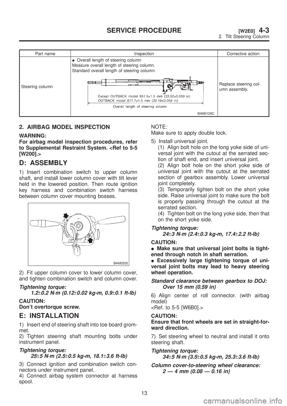
1) Insert combination switch to upper column
shaft, and install lower column cover with tilt lever
held in the lowered position. Then route ignition
key harness and combination switch harness
between column cover mounting bosses.
B4M0555
2) Fit upper column cover to lower column cover,
and tighten combination switch and column cover.
Tightening torque:
1.2
±0.2 N´m (0.12±0.02 kg-m, 0.9±0.1 ft-lb)
CAUTION:
Don't overtorque screw.
E: INSTALLATION
1) Insert end of steering shaft into toe board grom-
met.
2) Tighten steering shaft mounting bolts under
instrument panel.
Tightening torque:
25
±5 N´m (2.5±0.5 kg-m, 18.1±3.6 ft-lb)
3) Connect ignition and combination switch con-
nectors under instrument panel.
4) Connect airbag system connector at harness
spool.NOTE:
Make sure to apply double lock.
5) Install universal joint.
(1) Align bolt hole on the long yoke side of uni-
versal joint with the cutout at the serrated sec-
tion of shaft end, and insert universal joint.
(2) Align bolt hole on the short yoke side of
universal joint with the cutout at the serrated
section of gearbox assembly. Lower universal
joint completely.
(3) Temporarily tighten bolt on the short yoke
side. Raise universal joint to make sure the bolt
is properly passing through the cutout at the
serrated section.
(4) Tighten bolt on the long yoke side, then that
on the short yoke side.
Tightening torque:
24
±3 N´m (2.4±0.3 kg-m, 17.4±2.2 ft-lb)
CAUTION:
IMake sure that universal joint bolts is tight-
ened through notch in shaft serration.
IExcessively large tightening torque of uni-
versal joint bolts may lead to heavy steering
wheel operation.
Standard clearance between gearbox to DOJ:
Over 15 mm (0.59 in)
6) Align center of roll connector. (with airbag
model)
CAUTION:
Ensure that front wheels are set in straight-for-
ward direction.
7) Set steering wheel to neutral and install it onto
steering shaft.
Tightening torque:
34
±5 N´m (3.5±0.5 kg-m, 25.3±3.6 ft-lb)
Column cover-to-steering wheel clearance:
2Ð4mm(0.08 Ð 0.16 in)
13
[W2E0]4-3SERVICE PROCEDURE
2. Tilt Steering Column
Page 805 of 1456

CAUTION:
Insert roll connector guide pin into guide hole
on lower end of surface of steering wheel to
prevent damage.
Draw out airbag system connector, horn con-
nector and cruise control connectors from
guide hole of steering wheel lower end. (with
airbag model)
8) Install airbag module to steering wheel. (with
airbag model)
WARNING:
Always refer to 5-5 Supplemental Restraint
System before performing the service opera-
tion. 3. Steering Gearbox (Power
Steering System) [LHD model]
A: REMOVAL
NOTE:
For disassembly and assembly of gearbox unit,
refer to section Control Valve (Power Steering
Gearbox) [LHD model]. and
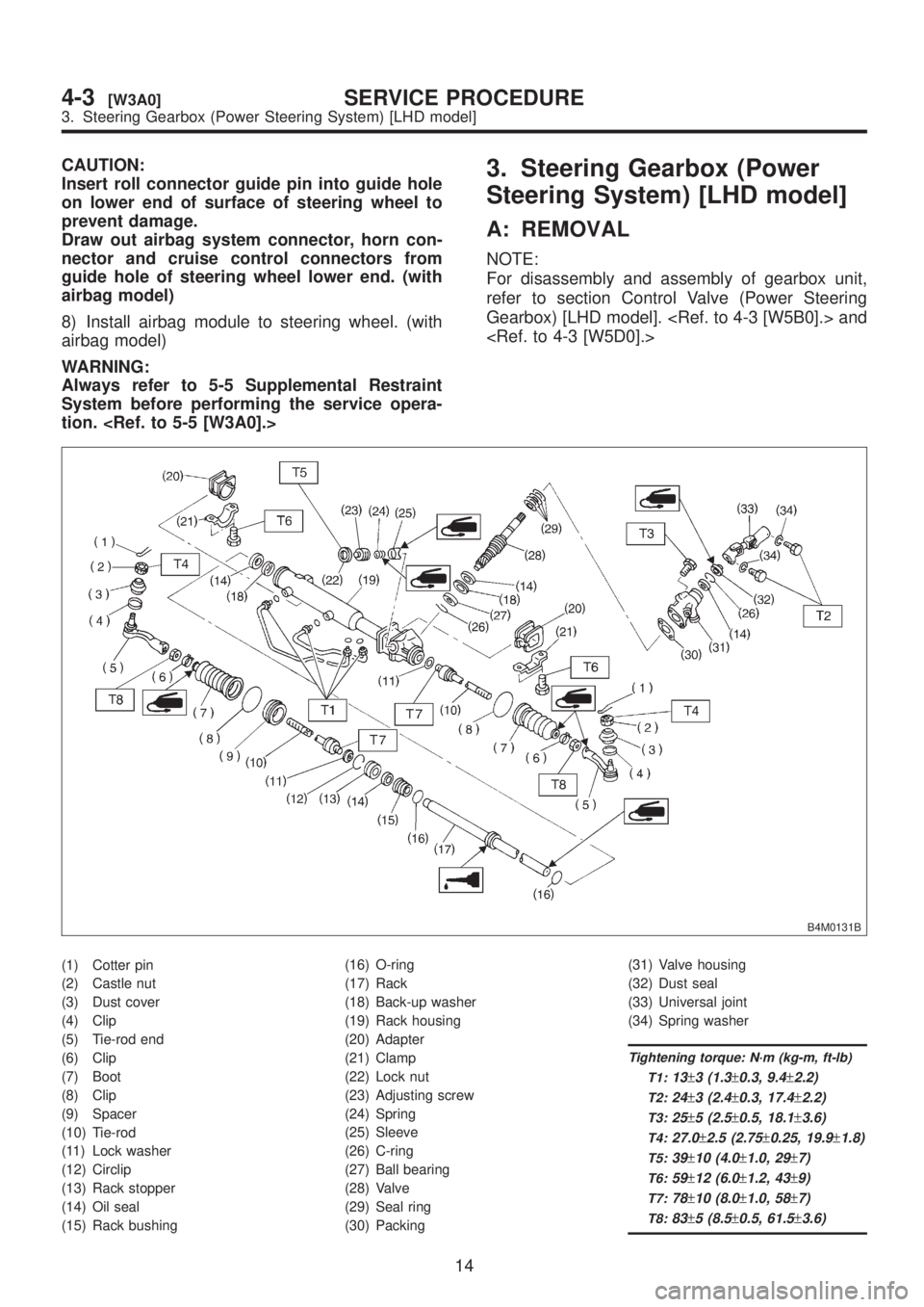
B4M0131B
(1) Cotter pin
(2) Castle nut
(3) Dust cover
(4) Clip
(5) Tie-rod end
(6) Clip
(7) Boot
(8) Clip
(9) Spacer
(10) Tie-rod
(11) Lock washer
(12) Circlip
(13) Rack stopper
(14) Oil seal
(15) Rack bushing(16) O-ring
(17) Rack
(18) Back-up washer
(19) Rack housing
(20) Adapter
(21) Clamp
(22) Lock nut
(23) Adjusting screw
(24) Spring
(25) Sleeve
(26) C-ring
(27) Ball bearing
(28) Valve
(29) Seal ring
(30) Packing(31) Valve housing
(32) Dust seal
(33) Universal joint
(34) Spring washer
Tightening torque: N´m (kg-m, ft-lb)
T1:
13±3 (1.3±0.3, 9.4±2.2)
T2:24±3 (2.4±0.3, 17.4±2.2)
T3:25±5 (2.5±0.5, 18.1±3.6)
T4:27.0±2.5 (2.75±0.25, 19.9±1.8)
T5:39±10 (4.0±1.0, 29±7)
T6:59±12 (6.0±1.2, 43±9)
T7:78±10 (8.0±1.0, 58±7)
T8:83±5 (8.5±0.5, 61.5±3.6)
14
4-3[W3A0]SERVICE PROCEDURE
3. Steering Gearbox (Power Steering System) [LHD model]
Page 806 of 1456

CAUTION:
Insert roll connector guide pin into guide hole
on lower end of surface of steering wheel to
prevent damage.
Draw out airbag system connector, horn con-
nector and cruise control connectors from
guide hole of steering wheel lower end. (with
airbag model)
8) Install airbag module to steering wheel. (with
airbag model)
WARNING:
Always refer to 5-5 Supplemental Restraint
System before performing the service opera-
tion. 3. Steering Gearbox (Power
Steering System) [LHD model]
A: REMOVAL
NOTE:
For disassembly and assembly of gearbox unit,
refer to section Control Valve (Power Steering
Gearbox) [LHD model]. and
B4M0131B
(1) Cotter pin
(2) Castle nut
(3) Dust cover
(4) Clip
(5) Tie-rod end
(6) Clip
(7) Boot
(8) Clip
(9) Spacer
(10) Tie-rod
(11) Lock washer
(12) Circlip
(13) Rack stopper
(14) Oil seal
(15) Rack bushing(16) O-ring
(17) Rack
(18) Back-up washer
(19) Rack housing
(20) Adapter
(21) Clamp
(22) Lock nut
(23) Adjusting screw
(24) Spring
(25) Sleeve
(26) C-ring
(27) Ball bearing
(28) Valve
(29) Seal ring
(30) Packing(31) Valve housing
(32) Dust seal
(33) Universal joint
(34) Spring washer
Tightening torque: N´m (kg-m, ft-lb)
T1:
13±3 (1.3±0.3, 9.4±2.2)
T2:24±3 (2.4±0.3, 17.4±2.2)
T3:25±5 (2.5±0.5, 18.1±3.6)
T4:27.0±2.5 (2.75±0.25, 19.9±1.8)
T5:39±10 (4.0±1.0, 29±7)
T6:59±12 (6.0±1.2, 43±9)
T7:78±10 (8.0±1.0, 58±7)
T8:83±5 (8.5±0.5, 61.5±3.6)
14
4-3[W3A0]SERVICE PROCEDURE
3. Steering Gearbox (Power Steering System) [LHD model]
Page 941 of 1456

4) Install front ABS sensor on strut and wheel
apron bracket.
Tightening torque:
32
±10 N´m (3.3±1.0 kg-m, 24±7 ft-lb)
B4M1442A
5) Place a thickness gauge between ABS sensor's
pole piece and tone wheel's tooth face. After stan-
dard clearance is obtained over the entire
perimeter, tighten ABS sensor on housing to speci-
fied torque.
ABS sensor standard clearance:
0.9 Ð 1.4 mm (0.035 Ð 0.055 in)
Tightening torque:
32
±10 N´m (3.3±1.0 kg-m, 24±7 ft-lb)
CAUTION:
Check the marks on the harness to make sure
that no distortion exists. (RH: white, LH: yel-
low)
NOTE:
If the clearance is outside specifications, readjust.
17. Brake Pipe
A: SUPPLEMENTAL RESTRAINT
SYSTEM ªAIRBAGº
Airbag system wiring harness is routed near the
center brake pipe.
CAUTION:
IAll Airbag system wiring harness and con-
nectors are colored yellow. Do not use electri-
cal test equipment on these circuit.
IBe careful not to damage Airbag system wir-
ing harness when servicing the center brake
pipe.
B: REMOVAL AND INSTALLATION
CAUTION:
IWhen removing and installing the brake
pipe, make sure that it is not bent.
IAfter installing the brake pipe and hose,
bleed the air.
IAfter installing the brake hose, make sure
that it does not touch the tire or suspension
assembly, etc.
Brake pipe tightening torque:
15+3/þ2N´m (1.5+0.3/þ0.2kg-m, 10.8+2.2/þ1.4ft-lb)
63
[W17B0]4-4SERVICE PROCEDURE
17. Brake Pipe
Page 942 of 1456

4) Install front ABS sensor on strut and wheel
apron bracket.
Tightening torque:
32
±10 N´m (3.3±1.0 kg-m, 24±7 ft-lb)
B4M1442A
5) Place a thickness gauge between ABS sensor's
pole piece and tone wheel's tooth face. After stan-
dard clearance is obtained over the entire
perimeter, tighten ABS sensor on housing to speci-
fied torque.
ABS sensor standard clearance:
0.9 Ð 1.4 mm (0.035 Ð 0.055 in)
Tightening torque:
32
±10 N´m (3.3±1.0 kg-m, 24±7 ft-lb)
CAUTION:
Check the marks on the harness to make sure
that no distortion exists. (RH: white, LH: yel-
low)
NOTE:
If the clearance is outside specifications, readjust.
17. Brake Pipe
A: SUPPLEMENTAL RESTRAINT
SYSTEM ªAIRBAGº
Airbag system wiring harness is routed near the
center brake pipe.
CAUTION:
IAll Airbag system wiring harness and con-
nectors are colored yellow. Do not use electri-
cal test equipment on these circuit.
IBe careful not to damage Airbag system wir-
ing harness when servicing the center brake
pipe.
B: REMOVAL AND INSTALLATION
CAUTION:
IWhen removing and installing the brake
pipe, make sure that it is not bent.
IAfter installing the brake pipe and hose,
bleed the air.
IAfter installing the brake hose, make sure
that it does not touch the tire or suspension
assembly, etc.
Brake pipe tightening torque:
15+3/þ2N´m (1.5+0.3/þ0.2kg-m, 10.8+2.2/þ1.4ft-lb)
63
[W17B0]4-4SERVICE PROCEDURE
17. Brake Pipe