Page 967 of 1456
1. Precaution
A: SUPPLEMENTAL RESTRAINT
SYSTEM ªAIRBAGº
CAUTION:
IAll Airbag system wiring harness and con-
nectors are colored yellow. Do not use electri-
cal test equipment on these circuit.
IBe careful not to damage Airbag system wir-
ing harness when servicing the instrument
panel, heater unit, blower motor and control
unit.
Airbag system wiring harness is routed near the
instrument panel, heater unit, blower motor and
control unit.
2. Heater Unit
A: REMOVAL AND INSTALLATION
1) Disconnect GND cable from battery.
2) Remove heater hoses (inlet, outlet) in engine
compartment.
NOTE:
Drain as much coolant from heater unit as
possible, and plug disconnected hose with cloth.
3) Remove instrument panel.
[W1A0].>
4) Remove steering support beam.
[C600].>
5) Remove evaporator. (With A/C model)
4-7 [W14A0].>
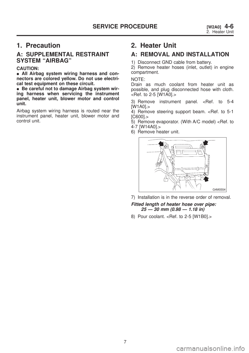
6) Remove heater unit.
G4M0554
7) Installation is in the reverse order of removal.
Fitted length of heater hose over pipe:
25 Ð 30 mm (0.98 Ð 1.18 in)
8) Pour coolant.
7
[W2A0]4-6SERVICE PROCEDURE
2. Heater Unit
Page 968 of 1456
1. Precaution
A: SUPPLEMENTAL RESTRAINT
SYSTEM ªAIRBAGº
CAUTION:
IAll Airbag system wiring harness and con-
nectors are colored yellow. Do not use electri-
cal test equipment on these circuit.
IBe careful not to damage Airbag system wir-
ing harness when servicing the instrument
panel, heater unit, blower motor and control
unit.
Airbag system wiring harness is routed near the
instrument panel, heater unit, blower motor and
control unit.
2. Heater Unit
A: REMOVAL AND INSTALLATION
1) Disconnect GND cable from battery.
2) Remove heater hoses (inlet, outlet) in engine
compartment.
NOTE:
Drain as much coolant from heater unit as
possible, and plug disconnected hose with cloth.
3) Remove instrument panel.
[W1A0].>
4) Remove steering support beam.
[C600].>
5) Remove evaporator. (With A/C model)
4-7 [W14A0].>
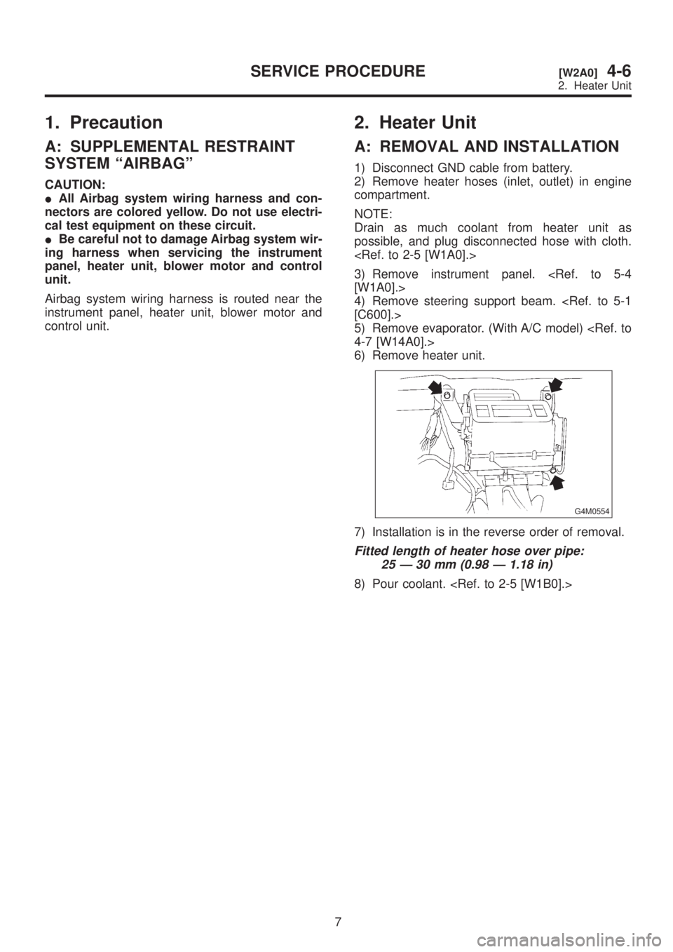
6) Remove heater unit.
G4M0554
7) Installation is in the reverse order of removal.
Fitted length of heater hose over pipe:
25 Ð 30 mm (0.98 Ð 1.18 in)
8) Pour coolant.
7
[W2A0]4-6SERVICE PROCEDURE
2. Heater Unit
Page 1025 of 1456
1. Precaution
A: SUPPLEMENTAL RESTRAINT
SYSTEM ªAIRBAGº
Airbag system wiring harness is routed on and
along body panels.
CAUTION:
IAll Airbag system wiring harness and con-
nectors are colored yellow. Do not use electri-
cal test equipment on these circuits.
IBe careful not to damage Airbag system wir-
ing harness when repairing the body panel.
2
5-1[S1A0]SPECIFICATIONS AND SERVICE DATA
1. Precaution
Page 1148 of 1456
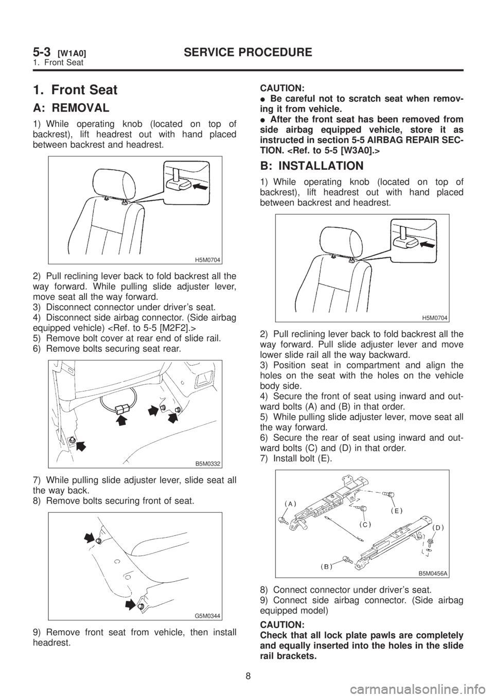
1. Front Seat
A: REMOVAL
1) While operating knob (located on top of
backrest), lift headrest out with hand placed
between backrest and headrest.
H5M0704
2) Pull reclining lever back to fold backrest all the
way forward. While pulling slide adjuster lever,
move seat all the way forward.
3) Disconnect connector under driver's seat.
4) Disconnect side airbag connector. (Side airbag
equipped vehicle)
5) Remove bolt cover at rear end of slide rail.
6) Remove bolts securing seat rear.
B5M0332
7) While pulling slide adjuster lever, slide seat all
the way back.
8) Remove bolts securing front of seat.
G5M0344
9) Remove front seat from vehicle, then install
headrest.CAUTION:
IBe careful not to scratch seat when remov-
ing it from vehicle.
IAfter the front seat has been removed from
side airbag equipped vehicle, store it as
instructed in section 5-5 AIRBAG REPAIR SEC-
TION.
B: INSTALLATION
1) While operating knob (located on top of
backrest), lift headrest out with hand placed
between backrest and headrest.
H5M0704
2) Pull reclining lever back to fold backrest all the
way forward. Pull slide adjuster lever and move
lower slide rail all the way backward.
3) Position seat in compartment and align the
holes on the seat with the holes on the vehicle
body side.
4) Secure the front of seat using inward and out-
ward bolts (A) and (B) in that order.
5) While pulling slide adjuster lever, move seat all
the way forward.
6) Secure the rear of seat using inward and out-
ward bolts (C) and (D) in that order.
7) Install bolt (E).
B5M0456A
8) Connect connector under driver's seat.
9) Connect side airbag connector. (Side airbag
equipped model)
CAUTION:
Check that all lock plate pawls are completely
and equally inserted into the holes in the slide
rail brackets.
8
5-3[W1A0]SERVICE PROCEDURE
1. Front Seat
Page 1157 of 1456
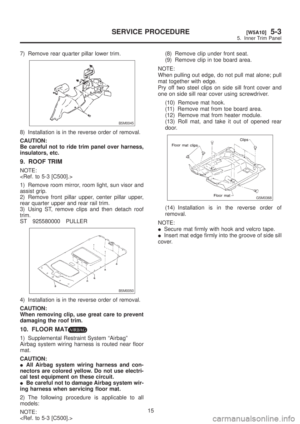
7) Remove rear quarter pillar lower trim.
B5M0045
8) Installation is in the reverse order of removal.
CAUTION:
Be careful not to ride trim panel over harness,
insulators, etc.
9. ROOF TRIM
NOTE:
1) Remove room mirror, room light, sun visor and
assist grip.
2) Remove front pillar upper, center pillar upper,
rear quarter upper and rear rail trim.
3) Using ST, remove clips and then detach roof
trim.
ST 925580000 PULLER
B5M0050
4) Installation is in the reverse order of removal.
CAUTION:
When removing clip, use great care to prevent
damaging the roof trim.
10. FLOOR MAT
1) Supplemental Restraint System ªAirbagº
Airbag system wiring harness is routed near floor
mat.
CAUTION:
IAll Airbag system wiring harness and con-
nectors are colored yellow. Do not use electri-
cal test equipment on these circuit.
IBe careful not to damage Airbag system wir-
ing harness when servicing floor mat.
2) The following procedure is applicable to all
models:
NOTE:
(8) Remove clip under front seat.
(9) Remove clip in toe board area.
NOTE:
When pulling out edge, do not pull mat alone; pull
mat together with edge.
Pry off two steel clips on side sill front cover and
one on side sill rear cover using screwdriver.
(10) Remove mat hook.
(11) Remove mat from toe board area.
(12) Remove mat from heater module.
(13) Roll mat, and take it out of opened rear
door.
G5M0368
(14) Installation is in the reverse order of
removal.
NOTE:
ISecure mat firmly with hook and velcro tape.
IInsert mat edge firmly into the groove of side sill
cover.
15
[W5A10]5-3SERVICE PROCEDURE
5. Inner Trim Panel
Page 1161 of 1456
1. Instrument Panel
A: REMOVAL
Airbag system wiring harness is routed near com-
bination meter.
CAUTION:
IAll Airbag system wiring harness and con-
nectors are colored yellow. Do not use electri-
cal test equipment on these circuits.
IBe careful not to damage Airbag system wir-
ing harness when servicing the combination
meter.
1) Disconnect GND cable from battery.
2) Remove shift knob (MT model).
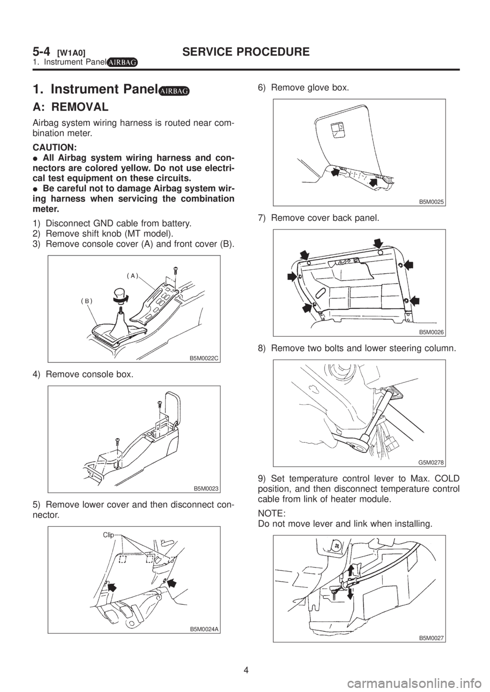
3) Remove console cover (A) and front cover (B).
B5M0022C
4) Remove console box.
B5M0023
5) Remove lower cover and then disconnect con-
nector.
B5M0024A
6) Remove glove box.
B5M0025
7) Remove cover back panel.
B5M0026
8) Remove two bolts and lower steering column.
G5M0278
9) Set temperature control lever to Max. COLD
position, and then disconnect temperature control
cable from link of heater module.
NOTE:
Do not move lever and link when installing.
B5M0027
4
5-4[W1A0]SERVICE PROCEDURE
1. Instrument Panel
Page 1162 of 1456
10) Remove bolt cover and bolt of both side.
B5M0028
11) Remove front side sill cover RH and then dis-
connect airbag connector (AB9) and (AB10) (Air-
bag model).
B5M0029A
12) Disconnect harness connectors and then remove the installing bolt.
CAUTION:
Be sure to hold socket section and not harness when disconnecting.
NOTE:
Put matching mark, if necessary, for easy re-assembly.
B5M0030B
(1) 15P/Gray
(2) 22P/Brown
(3) 22P/White(4) 20P/Blue
(5) 22P/Black
(6) 4P/Sky blue(7) 1P/Black
(8) 1P/Black
5
[W1A0]5-4SERVICE PROCEDURE
1. Instrument Panel
Page 1163 of 1456
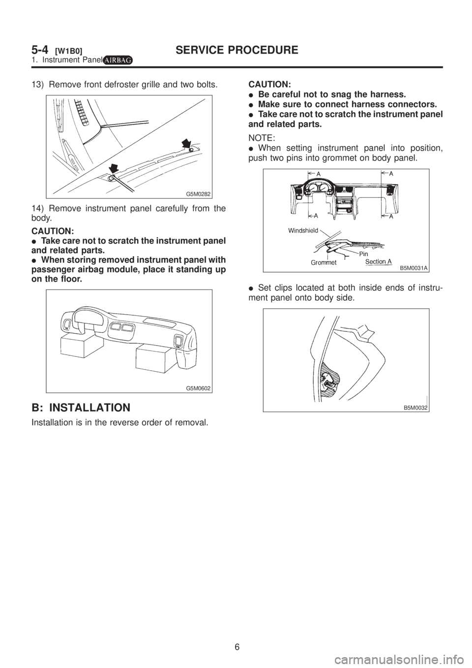
13) Remove front defroster grille and two bolts.
G5M0282
14) Remove instrument panel carefully from the
body.
CAUTION:
ITake care not to scratch the instrument panel
and related parts.
IWhen storing removed instrument panel with
passenger airbag module, place it standing up
on the floor.
G5M0602
B: INSTALLATION
Installation is in the reverse order of removal.CAUTION:
IBe careful not to snag the harness.
IMake sure to connect harness connectors.
ITake care not to scratch the instrument panel
and related parts.
NOTE:
IWhen setting instrument panel into position,
push two pins into grommet on body panel.
B5M0031A
ISet clips located at both inside ends of instru-
ment panel onto body side.
B5M0032
6
5-4[W1B0]SERVICE PROCEDURE
1. Instrument Panel
![SUBARU LEGACY 1999 Service Repair Manual 10) Remove bolt cover and bolt of both side.
B5M0028
11) Remove front side sill cover RH and then dis-
connect airbag connector (AB9) and (AB10) (Air-
bag model). <Ref. to 5-5 [M200].>
B5M0029A
12) Di](/manual-img/17/57435/w960_57435-1161.png "SUBARU LEGACY 1999 Service Repair Manual 10) Remove bolt cover and bolt of both side.
B5M0028
11) Remove front side sill cover RH and then dis-
connect airbag connector (AB9) and (AB10) (Air-
bag model). <Ref. to 5-5 [M200].>
B5M0029A
12) Di")