1999 SUBARU LEGACY suspension
[x] Cancel search: suspensionPage 705 of 1456
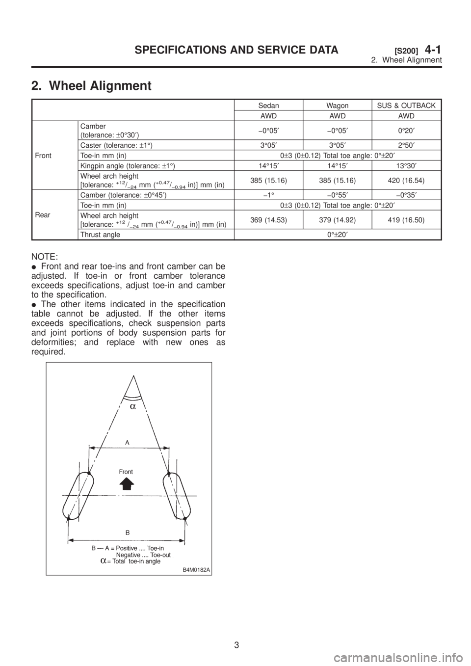
2. Wheel Alignment
Sedan Wagon SUS & OUTBACK
AWD AWD AWD
FrontCamber
(tolerance:±0É30¢)þ0É05¢þ0É05¢0É20¢
Caster (tolerance:±1É) 3É05¢3É05¢2É50¢
Toe-in mm (in) 0±3(0±0.12) Total toe angle: 0ɱ20¢
Kingpin angle (tolerance:±1É) 14É15¢14É15¢13É30¢
Wheel arch height
[tolerance:
+12/þ24mm (+0.47/þ0.94in)] mm (in)385 (15.16) 385 (15.16) 420 (16.54)
RearCamber (tolerance:±0É45¢) þ1É þ0É55¢þ0É35¢
Toe-in mm (in) 0±3(0±0.12) Total toe angle: 0ɱ20¢
Wheel arch height
[tolerance:
+12/þ24mm (+0.47/þ0.94in)] mm (in)369 (14.53) 379 (14.92) 419 (16.50)
Thrust angle 0ɱ20¢
NOTE:
IFront and rear toe-ins and front camber can be
adjusted. If toe-in or front camber tolerance
exceeds specifications, adjust toe-in and camber
to the specification.
IThe other items indicated in the specification
table cannot be adjusted. If the other items
exceeds specifications, check suspension parts
and joint portions of body suspension parts for
deformities; and replace with new ones as
required.
B4M0182A
3
[S200]4-1SPECIFICATIONS AND SERVICE DATA
2. Wheel Alignment
Page 706 of 1456
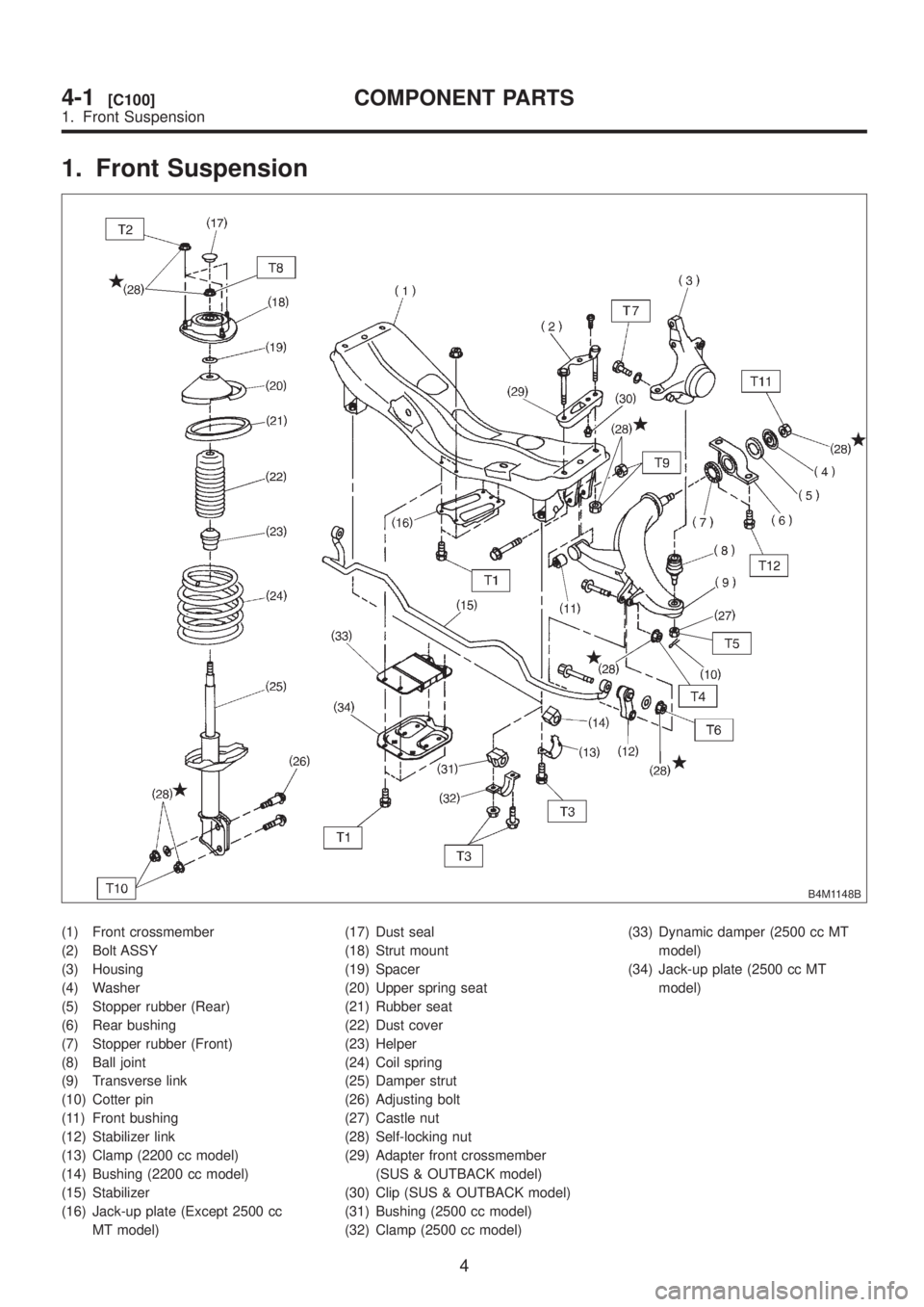
1. Front Suspension
B4M1148B
(1) Front crossmember
(2) Bolt ASSY
(3) Housing
(4) Washer
(5) Stopper rubber (Rear)
(6) Rear bushing
(7) Stopper rubber (Front)
(8) Ball joint
(9) Transverse link
(10) Cotter pin
(11) Front bushing
(12) Stabilizer link
(13) Clamp (2200 cc model)
(14) Bushing (2200 cc model)
(15) Stabilizer
(16) Jack-up plate (Except 2500 cc
MT model)(17) Dust seal
(18) Strut mount
(19) Spacer
(20) Upper spring seat
(21) Rubber seat
(22) Dust cover
(23) Helper
(24) Coil spring
(25) Damper strut
(26) Adjusting bolt
(27) Castle nut
(28) Self-locking nut
(29) Adapter front crossmember
(SUS & OUTBACK model)
(30) Clip (SUS & OUTBACK model)
(31) Bushing (2500 cc model)
(32) Clamp (2500 cc model)(33) Dynamic damper (2500 cc MT
model)
(34) Jack-up plate (2500 cc MT
model)
4
4-1[C100]COMPONENT PARTS
1. Front Suspension
Page 707 of 1456
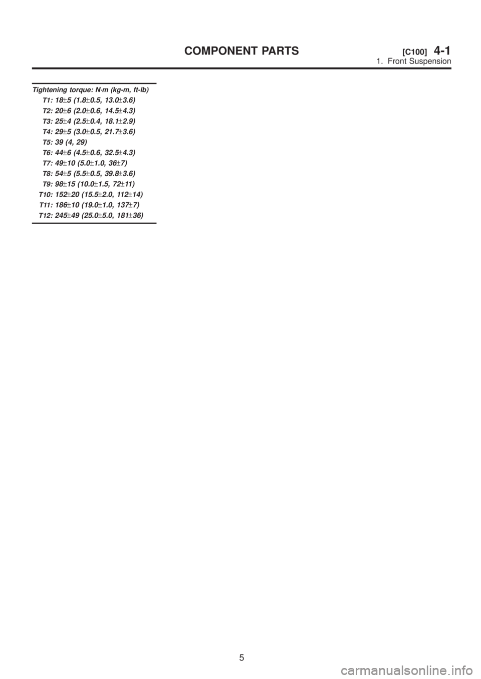
Tightening torque: N´m (kg-m, ft-lb)
T1:
18±5 (1.8±0.5, 13.0±3.6)
T2:20±6 (2.0±0.6, 14.5±4.3)
T3:25±4 (2.5±0.4, 18.1±2.9)
T4:29±5 (3.0±0.5, 21.7±3.6)
T5:39 (4, 29)
T6:44±6 (4.5±0.6, 32.5±4.3)
T7:49±10 (5.0±1.0, 36±7)
T8:54±5 (5.5±0.5, 39.8±3.6)
T9:98±15 (10.0±1.5, 72±11 )
T10:152±20 (15.5±2.0, 112±14)
T11:186±10 (19.0±1.0, 137±7)
T12:245±49 (25.0±5.0, 181±36)
5
[C100]4-1COMPONENT PARTS
1. Front Suspension
Page 708 of 1456

2. Rear Suspension
B4M0766B
(1) Stabilizer
(2) Stabilizer bracket
(3) Stabilizer bushing
(4) Clamp
(5) Floating bushing
(6) Stopper
(7) Stabilizer link
(8) Rear lateral link
(9) Bushing (C)
(10) Bushing (A)
(11) Front lateral link
(12) Bushing (B)
(13) Trailing link rear bushing
(14) Trailing link
(15) Trailing link front bushing
(16) Trailing link bracket(17) Cap (Protection)
(18) Washer
(19) Rear crossmember
(20) Strut mount cap
(21) Strut mount
(22) Rubber seat upper
(23) Dust cover
(24) Coil spring
(25) Helper
(26) Rubber seat lower
(27) Damper strut
(28) Self-locking nut
(29) Crossmember reinforcement
lower (Sedan model and except
SUS model)(30) Adapter rear crossmember (SUS
& OUTBACK model)
Tightening torque: N´m (kg-m, ft-lb)
T1:
20±6 (2.0±0.6, 14.5±4.3)
T2:25±7 (2.5±0.7, 18.1±5.1)
T3:44±6 (4.5±0.6, 32.5±4.3)
T4:59±10 (6.0±1.0, 43±7)
T5:98±15 (10.0±1.5, 72±11 )
T6:98±20 (10.0±2.0, 72±14)
T7:11 3±15 (11.5±1.5, 83±11 )
T8:127±20 (13.0±2.0, 94±14)
T9:137±20 (14.0±2.0, 101±14)
T10:196+39/þ10(20.0+4.0/þ1.0, 145+29/þ7)
6
4-1[C200]COMPONENT PARTS
2. Rear Suspension
Page 714 of 1456

6. THRUST ANGLE
IInspection
1) Position vehicle on a level surface.
2) Move vehicle 3 to 4 meters directly forward.
3) Determine locus of both front and rear axles.
4) Measure distance ªLº between center line of
loci of the axles.
Thrust angle:
Less than 20
¢when ªLº is equal to or
less than 15 mm (0.59 in).
G4M0488
IAdjustment
1) Make thrust angle adjustments by turning toe-in
adjusting bolts of rear suspension equally in the
same direction.
2) When one rear wheel is adjusted in a toe-in
direction, adjust the other rear wheel equally in
toe-out direction, in order to make thrust angle
adjustment.
3) When left and right adjusting bolts are turned
incrementally by one graduation in the same
direction, the thrust angle will change approxi-
mately 10' [ªLº is almost equal to 7.5 mm (0.295
in)].
Thrust angle:
0É
±20¢
G4M0488
12
4-1[W1B6]SERVICE PROCEDURE
1. On-car Services
Page 744 of 1456
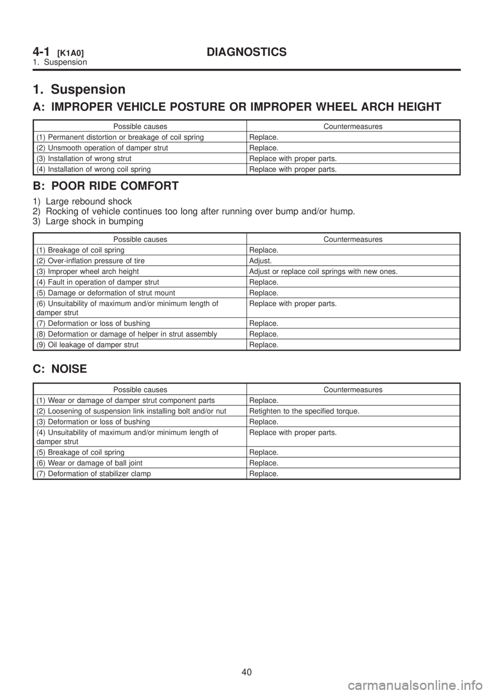
1. Suspension
A: IMPROPER VEHICLE POSTURE OR IMPROPER WHEEL ARCH HEIGHT
Possible causes Countermeasures
(1) Permanent distortion or breakage of coil spring Replace.
(2) Unsmooth operation of damper strut Replace.
(3) Installation of wrong strut Replace with proper parts.
(4) Installation of wrong coil spring Replace with proper parts.
B: POOR RIDE COMFORT
1) Large rebound shock
2) Rocking of vehicle continues too long after running over bump and/or hump.
3) Large shock in bumping
Possible causes Countermeasures
(1) Breakage of coil spring Replace.
(2) Over-inflation pressure of tire Adjust.
(3) Improper wheel arch height Adjust or replace coil springs with new ones.
(4) Fault in operation of damper strut Replace.
(5) Damage or deformation of strut mount Replace.
(6) Unsuitability of maximum and/or minimum length of
damper strutReplace with proper parts.
(7) Deformation or loss of bushing Replace.
(8) Deformation or damage of helper in strut assembly Replace.
(9) Oil leakage of damper strut Replace.
C: NOISE
Possible causes Countermeasures
(1) Wear or damage of damper strut component parts Replace.
(2) Loosening of suspension link installing bolt and/or nut Retighten to the specified torque.
(3) Deformation or loss of bushing Replace.
(4) Unsuitability of maximum and/or minimum length of
damper strutReplace with proper parts.
(5) Breakage of coil spring Replace.
(6) Wear or damage of ball joint Replace.
(7) Deformation of stabilizer clamp Replace.
40
4-1[K1A0]DIAGNOSTICS
1. Suspension
Page 863 of 1456
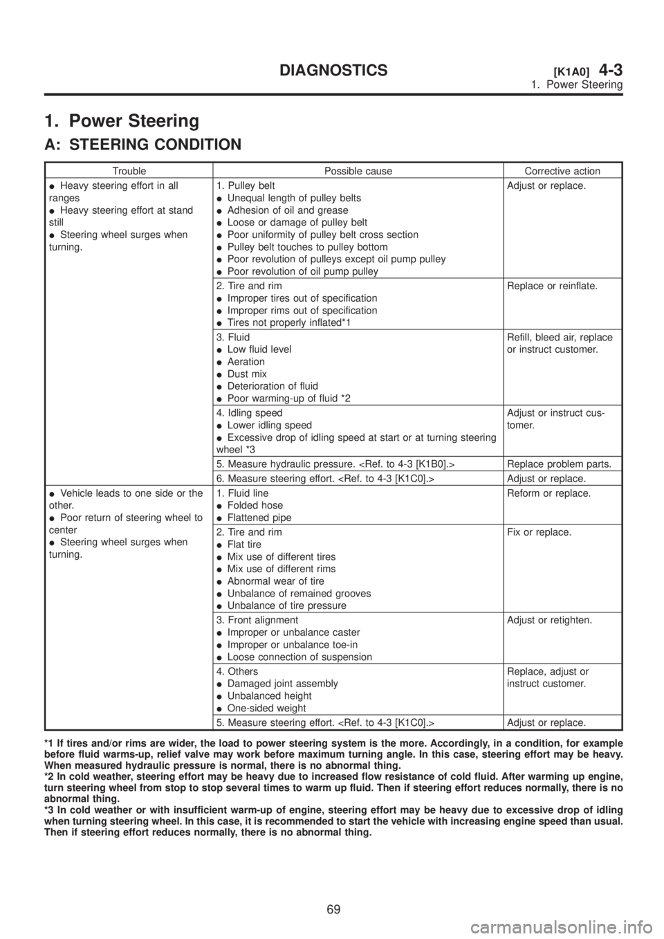
1. Power Steering
A: STEERING CONDITION
Trouble Possible cause Corrective action
IHeavy steering effort in all
ranges
IHeavy steering effort at stand
still
ISteering wheel surges when
turning.1. Pulley belt
IUnequal length of pulley belts
IAdhesion of oil and grease
ILoose or damage of pulley belt
IPoor uniformity of pulley belt cross section
IPulley belt touches to pulley bottom
IPoor revolution of pulleys except oil pump pulley
IPoor revolution of oil pump pulleyAdjust or replace.
2. Tire and rim
IImproper tires out of specification
IImproper rims out of specification
ITires not properly inflated*1Replace or reinflate.
3. Fluid
ILow fluid level
IAeration
IDust mix
IDeterioration of fluid
IPoor warming-up of fluid *2Refill, bleed air, replace
or instruct customer.
4. Idling speed
ILower idling speed
IExcessive drop of idling speed at start or at turning steering
wheel *3Adjust or instruct cus-
tomer.
5. Measure hydraulic pressure.
6. Measure steering effort.
IVehicle leads to one side or the
other.
IPoor return of steering wheel to
center
ISteering wheel surges when
turning.1. Fluid line
IFolded hose
IFlattened pipeReform or replace.
2. Tire and rim
IFlat tire
IMix use of different tires
IMix use of different rims
IAbnormal wear of tire
IUnbalance of remained grooves
IUnbalance of tire pressureFix or replace.
3. Front alignment
IImproper or unbalance caster
IImproper or unbalance toe-in
ILoose connection of suspensionAdjust or retighten.
4. Others
IDamaged joint assembly
IUnbalanced height
IOne-sided weightReplace, adjust or
instruct customer.
5. Measure steering effort.
*1 If tires and/or rims are wider, the load to power steering system is the more. Accordingly, in a condition, for example
before fluid warms-up, relief valve may work before maximum turning angle. In this case, steering effort may be heavy.
When measured hydraulic pressure is normal, there is no abnormal thing.
*2 In cold weather, steering effort may be heavy due to increased flow resistance of cold fluid. After warming up engine,
turn steering wheel from stop to stop several times to warm up fluid. Then if steering effort reduces normally, there is no
abnormal thing.
*3 In cold weather or with insufficient warm-up of engine, steering effort may be heavy due to excessive drop of idling
when turning steering wheel. In this case, it is recommended to start the vehicle with increasing engine speed than usual.
Then if steering effort reduces normally, there is no abnormal thing.
69
[K1A0]4-3DIAGNOSTICS
1. Power Steering
Page 869 of 1456
![SUBARU LEGACY 1999 Service Repair Manual Trouble Possible cause Corrective action
Rattling noise (intermittent)
While engine is running.Interference with adjacent parts Check clearance.
Correct if necessary.
<Ref. to 4-3 [K1F0].>
Loosened in SUBARU LEGACY 1999 Service Repair Manual Trouble Possible cause Corrective action
Rattling noise (intermittent)
While engine is running.Interference with adjacent parts Check clearance.
Correct if necessary.
<Ref. to 4-3 [K1F0].>
Loosened in](/manual-img/17/57435/w960_57435-868.png)
Trouble Possible cause Corrective action
Rattling noise (intermittent)
While engine is running.Interference with adjacent parts Check clearance.
Correct if necessary.
Loosened installation of oil pump, oil tank, pump bracket, gear-
box or crossmemberRetighten.
Loosened installation of oil pump pulley or other pulley(s) Retighten.
Loosened linkage or play of steering or suspension
Loosened tightening of joint or steering columnRetighten or replace.
Sound generates from the inside of gearbox or oil pump. Replace the gearbox or oil
pump.
Knocking
When turning steering wheel
in both direction with small
angle repeatedly at engine
ON or OFF.Excessive backlash
Loosened lock nut for adjusting backlashAdjust and retighten.
Loosened tightening or play of tie-rod, tie-rod end Retighten or replace.
Grinding noise (continuous)
While engine is running.Vane pump aeration Inspect and retighten fluid line
connection.
Refill fluid and vent air.
Vane pump seizing Replace oil pump.
Pulley bearing seizing of oil pump Replace oil pump.
Folded hose, flat pipe Replace.
Squeal, squeak (intermittent
or continuous)
While engine is running.Maladjustment of pulley belt
Damaged or charged pulley belt
Unequal length of pulley beltsAdjust or replace.
(Replace two belts as a set.)
Run out or soilage of V-groove surface of oil pump pulley Clean or replace.
Sizzling noise (continuous)
While engine is running.Fluid aeration Fix wrong part causing aera-
tion.
Replace fluid and vent air.
Damaged pipe of gearbox Replace pipe.
Abnormal inside of hose or pipe
Flat hose or pipeRectify or replace.
Abnormal inside of oil tank Replace.
Removed oil tank cap Install cap.
Whistle (continuous)
While engine is running.Abnormal pipe of gearbox or abnormal inside of hose Replace bad parts of gearbox
or hose.
Whine or growl (continuous or
intermittent)
While engine is running with/
without steering turned.Loosened installation of oil pump, oil pump bracket Retighten.
Abnormal inside of oil pump, hose Replace oil pump, hose, if the
noise can be heard when run-
ning as well as stand still.
Torque converter growl air conditioner compression growl Remove power steering pul-
ley belt and confirm.
Creaking noise (intermittent)
While engine is running with
steering turned.Abnormal inside of gearbox Replace bad parts of gear-
box.
Abnormal bearing for steering shaft Apply grease or replace.
Generates when turning steering wheel with brake (service or
parking) applied.If the noise goes off when
brake is released, it is normal.
Vibration
While engine is running with/
without steering turned.Too low engine speed at start Adjust and instruct custom-
ers.
Vane pump aeration Fix wrong part.
Vent air.
Damaged valve in oil pump, gearbox Replace oil pump, bad parts
of gearbox.
Looseness of play of steering, suspension parts Retighten.
75
[K1E0]4-3DIAGNOSTICS
1. Power Steering