Page 1157 of 1456

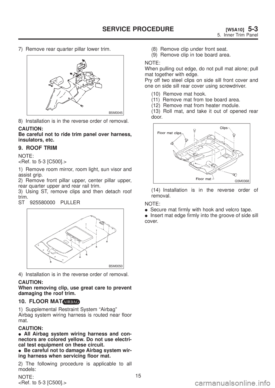
7) Remove rear quarter pillar lower trim.
B5M0045
8) Installation is in the reverse order of removal.
CAUTION:
Be careful not to ride trim panel over harness,
insulators, etc.
9. ROOF TRIM
NOTE:
1) Remove room mirror, room light, sun visor and
assist grip.
2) Remove front pillar upper, center pillar upper,
rear quarter upper and rear rail trim.
3) Using ST, remove clips and then detach roof
trim.
ST 925580000 PULLER
B5M0050
4) Installation is in the reverse order of removal.
CAUTION:
When removing clip, use great care to prevent
damaging the roof trim.
10. FLOOR MAT
1) Supplemental Restraint System ªAirbagº
Airbag system wiring harness is routed near floor
mat.
CAUTION:
IAll Airbag system wiring harness and con-
nectors are colored yellow. Do not use electri-
cal test equipment on these circuit.
IBe careful not to damage Airbag system wir-
ing harness when servicing floor mat.
2) The following procedure is applicable to all
models:
NOTE:
(8) Remove clip under front seat.
(9) Remove clip in toe board area.
NOTE:
When pulling out edge, do not pull mat alone; pull
mat together with edge.
Pry off two steel clips on side sill front cover and
one on side sill rear cover using screwdriver.
(10) Remove mat hook.
(11) Remove mat from toe board area.
(12) Remove mat from heater module.
(13) Roll mat, and take it out of opened rear
door.
G5M0368
(14) Installation is in the reverse order of
removal.
NOTE:
ISecure mat firmly with hook and velcro tape.
IInsert mat edge firmly into the groove of side sill
cover.
15
[W5A10]5-3SERVICE PROCEDURE
5. Inner Trim Panel
Page 1166 of 1456
1. Precaution
IIf any of the airbag system parts such as
sensors, airbag module, airbag control module and
harness are damaged or deformed, replace with
new genuine parts.
G5M0291
IWhen servicing, be sure to turn the ignition
switch off, disconnect the negative (þ) battery ter-
minal then the positive (+) terminal in advance, and
wait for more than 20 seconds before starting
work.
G5M0292
IWhen checking the system, be sure to use a
digital circuit tester. Use of an analog circuit tester
may cause the airbag to activate erroneously. Do
not directly apply the tester probe to any connec-
tor terminal of the airbag. When checking, use a
test harness.
G5M0293
G5M0294
4
5-5[W100]SERVICE PROCEDURE
1. Precaution
Page 1167 of 1456
IDo not drop the airbag modulator parts, subject
it to high temperatures over 90ÉC (194ÉF), or apply
oil, grease, or water to it; otherwise, the internal
parts may be damaged and its reliability greatly
lowered.
G5M0295
IIf any damage or open is found on the SRS air-
bag system wire harness, do not attempt to repair
using soldering, etc. Be sure to replace the faulty
harness with a new genuine part.
G5M0296
IInstall the wire harness securely with the speci-
fied clips so as to avoid interference or jamming
with other parts.
G5M0297
IBefore connecting the airbag system to ground,
make sure that the grounding terminal is free from
paint and contamination.
IDo not allow water or oil to come in contact with
the connector terminals. Do not touch the connec-
tor terminals.
G5M0298
IWhen connecting or disconnecting airbag
connector, make sure ignition switch is OFF.
5
[W100]5-5SERVICE PROCEDURE
1. Precaution
Page 1172 of 1456
G5M0604
1. DRIVER'S AIRBAG MODULE
1) Set front wheels in straight ahead position.
2) Turn ignition switch off.
3) Disconnect ground cable from battery and wait
for at least 20 seconds before starting work.
10
5-5[W3A1]SERVICE PROCEDURE
3. Airbag Module
Page 1174 of 1456
4. Main Harness
A: REMOVAL AND INSTALLATION
1) Turn ignition switch off.
2) Disconnect ground cable from battery and wait
for at least 20 seconds before starting work.
3) Remove lower cover.
Disconnect airbag connector (AB3) and (AB8)
below steering column.
CAUTION:
Do not reconnect airbag connector at steering
column until main harness are securely re-in-
stalled.
G5M0312
4) Remove console box.
5) Disconnect connector from airbag control mod-
ule.
6) Disconnect body harness connector (B31) from
connector (AB1).
NOTE:
The following procedures for removal are for ªLHD
modelº. The procedures for ªRHD modelº are sym-
metrically opposite.
B5M0103B
7) Remove front side sill cover and then discon-
nect airbag connector (AB9) and (AB10).
5-5 [M2F2].>
B5M0029A
8) Roll up floor mat and side sill lower cover of
both side and then remove main harness.
12
5-5[W4A0]SERVICE PROCEDURE
4. Main Harness
Page 1176 of 1456

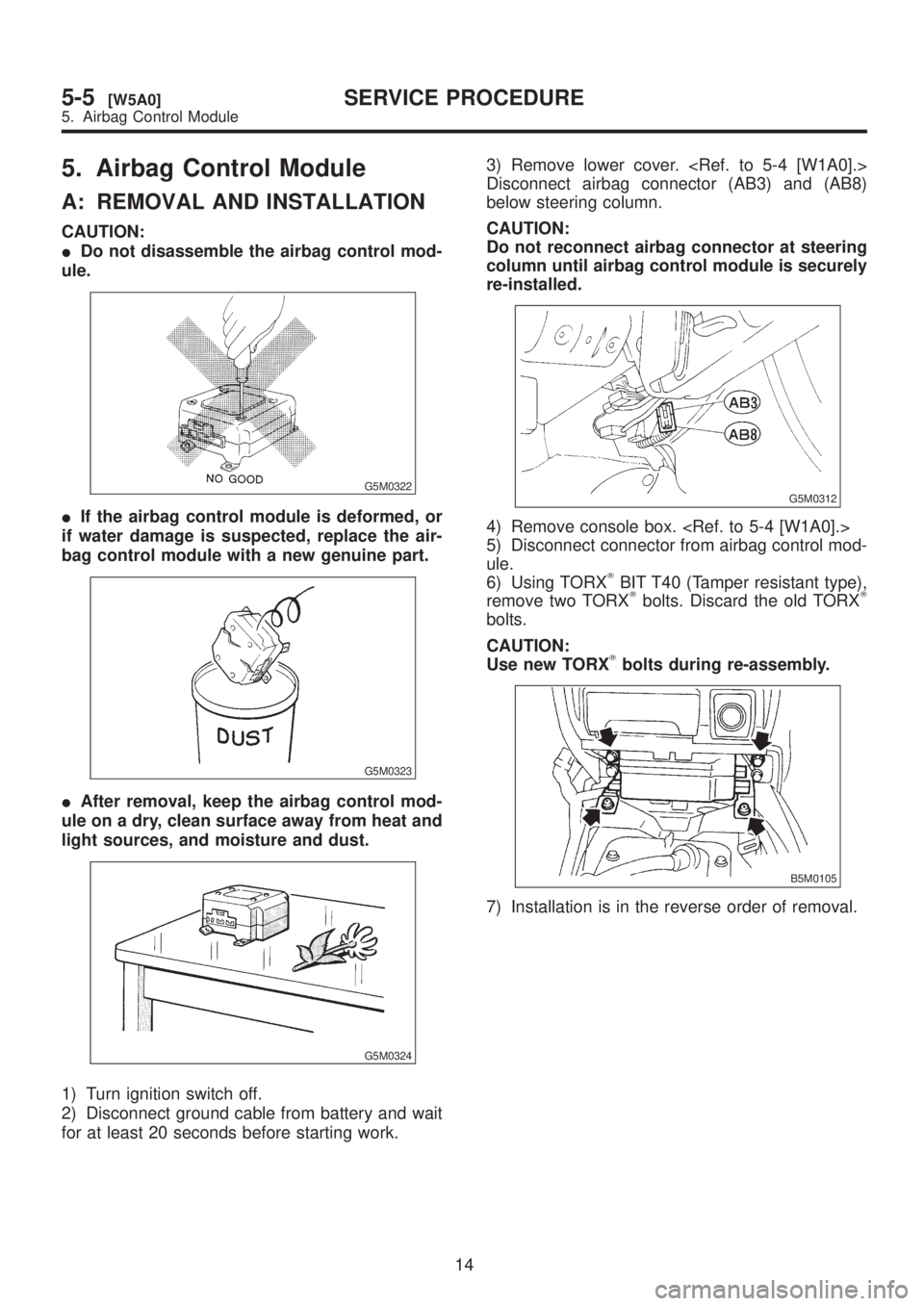
5. Airbag Control Module
A: REMOVAL AND INSTALLATION
CAUTION:
IDo not disassemble the airbag control mod-
ule.
G5M0322
IIf the airbag control module is deformed, or
if water damage is suspected, replace the air-
bag control module with a new genuine part.
G5M0323
IAfter removal, keep the airbag control mod-
ule on a dry, clean surface away from heat and
light sources, and moisture and dust.
G5M0324
1) Turn ignition switch off.
2) Disconnect ground cable from battery and wait
for at least 20 seconds before starting work.3) Remove lower cover.
Disconnect airbag connector (AB3) and (AB8)
below steering column.
CAUTION:
Do not reconnect airbag connector at steering
column until airbag control module is securely
re-installed.
G5M0312
4) Remove console box.
5) Disconnect connector from airbag control mod-
ule.
6) Using TORX
TBIT T40 (Tamper resistant type),
remove two TORXTbolts. Discard the old TORXT
bolts.
CAUTION:
Use new TORX
Tbolts during re-assembly.
B5M0105
7) Installation is in the reverse order of removal.
14
5-5[W5A0]SERVICE PROCEDURE
5. Airbag Control Module
Page 1177 of 1456
![SUBARU LEGACY 1999 Service Repair Manual 6. Combination Switch
A: REMOVAL
1) Turn ignition switch off.
2) Disconnect ground cable from battery and wait
for at least 20 seconds before starting work.
3) Remove lower cover. <Ref. to 5-4 [W1A0]. SUBARU LEGACY 1999 Service Repair Manual 6. Combination Switch
A: REMOVAL
1) Turn ignition switch off.
2) Disconnect ground cable from battery and wait
for at least 20 seconds before starting work.
3) Remove lower cover. <Ref. to 5-4 [W1A0].](/manual-img/17/57435/w960_57435-1176.png)
6. Combination Switch
A: REMOVAL
1) Turn ignition switch off.
2) Disconnect ground cable from battery and wait
for at least 20 seconds before starting work.
3) Remove lower cover.
Disconnect airbag connector (AB3) and (AB8)
below steering column.
CAUTION:
Do not reconnect airbag connector at steering
column until combination switch is securely re-
installed.
G5M0312
4) Disconnect combination switch connectors
from body harness connector.
5) Set front wheels in straight ahead position.
Using TORX
TBIT T30, remove two TORXTbolts.
H5M0662A
6) Disconnect airbag connector on back of airbag
module. Remove airbag
module, and place it with pad side facing upward.
H5M0664
7) Using steering puller, remove steering wheel.
CAUTION:
Do not allow connector to interfere when
removing steering wheel.
G5M0332
8) Remove steering column covers.
9) Removing two retaining screws, remove combi-
nation switch.
B5M0106
B: ADJUSTMENT
1. CENTERING ROLL CONNECTOR
Before installing steering wheel, make sure to cen-
ter roll connector built into combination switch.
1) Make sure that front wheels are positioned
straight ahead.
2) Install steering gearbox, steering shaft and
combination switch properly. Turn roll connector
pin (A) clockwise until it stops.
3) Then, back off roll connector pin (A) approxi-
mately 2.65 turns until ªGº marks aligned.
B5M0457A
15
[W6B1]5-5SERVICE PROCEDURE
6. Combination Switch
Page 1178 of 1456

C: INSTALLATION
CAUTION:
Failure to do this might damage roll connector.
1) Before installing combination switch, check to
ensure that combination switch is off and front
wheels are set in the straight ahead position.
2) Install column cover and center roll connector.
3) Install steering wheel in neutral position. Care-
fully insert roll connector pin (A) into hole on steer-
ing wheel.
NOTE:
If steering wheel angle requires fine adjustment,
adjust tie-rod.
B5M0457A
4) Install airbag module and lower cover in the
reverse order of removal.
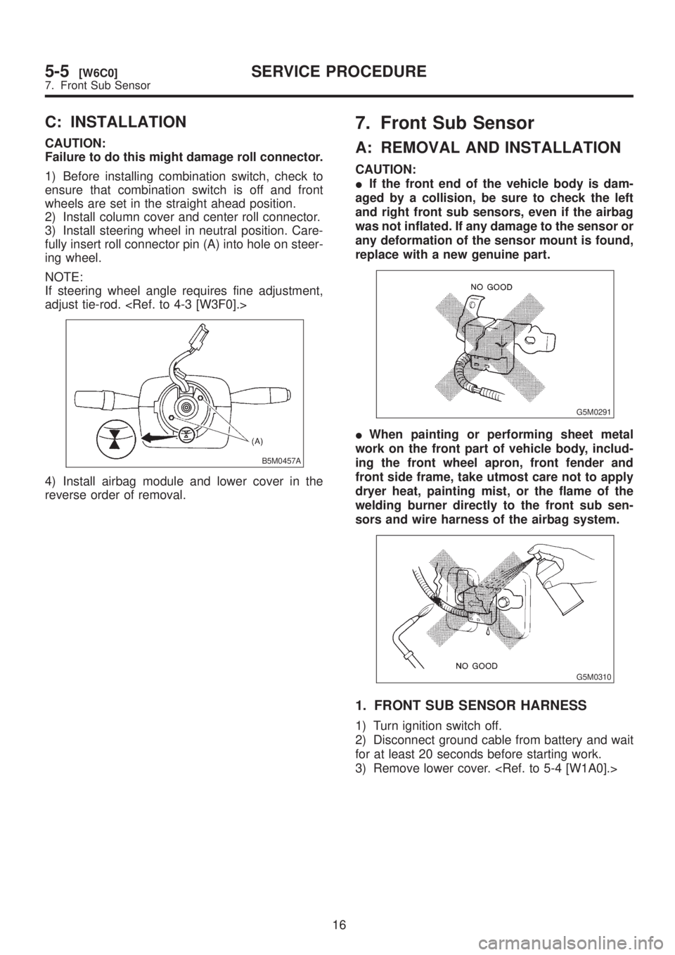
7. Front Sub Sensor
A: REMOVAL AND INSTALLATION
CAUTION:
IIf the front end of the vehicle body is dam-
aged by a collision, be sure to check the left
and right front sub sensors, even if the airbag
was not inflated. If any damage to the sensor or
any deformation of the sensor mount is found,
replace with a new genuine part.
G5M0291
IWhen painting or performing sheet metal
work on the front part of vehicle body, includ-
ing the front wheel apron, front fender and
front side frame, take utmost care not to apply
dryer heat, painting mist, or the flame of the
welding burner directly to the front sub sen-
sors and wire harness of the airbag system.
G5M0310
1. FRONT SUB SENSOR HARNESS
1) Turn ignition switch off.
2) Disconnect ground cable from battery and wait
for at least 20 seconds before starting work.
3) Remove lower cover.
16
5-5[W6C0]SERVICE PROCEDURE
7. Front Sub Sensor