Page 94 of 1456
5. Cylinder Head
A: REMOVAL
1. RELATED PARTS
1) Release fuel pressure.
2) Drain engine coolant.
3) Remove V-belt(s).
4) Remove generator and bracket.
5) Remove A/C compressor and bracket. (With
A/C model)6) Disconnect spark plug cords.
7) Remove connector bracket attaching bolt.
8) Remove camshaft position sensor and cam-
shaft position sensor support.
9) Disconnect oil pressure switch connector.
10) Disconnect blow-by hose.
11) Remove intake manifold.
[W4A0].>
2. CYLINDER HEAD
B2M2627A
(1) Rocker cover
(2) Cylinder head bolt(3) Cylinder head
(4) Cylinder head gasket
1) Remove timing belt, camshaft sprocket and
related parts.
2) Remove oil level gauge guide attaching bolt
(left hand only) and oil level gauge guide.
3) Remove rocker cover.
40
2-3a[W5A1]SERVICE PROCEDURE
5. Cylinder Head
Page 104 of 1456

2) Tighten cylinder head bolts.
(1) Apply a coat of engine oil to washers and
bolt threads.
(2) Tighten all bolts to 29 N´m (3.0 kg-m, 22
ft-lb) in alphabetical sequence.
Then tighten all bolts to 69 N´m (7.0 kg-m, 51
ft-lb) in alphabetical sequence.
(3) Back off all bolts by 180É first; back them off
by 180É again.
(4) Tighten bolts (a) and (b) to 34 N´m (3.5
kg-m, 25 ft-lb).
(5) Tighten bolts (c), (d), (e) and (f) to 15 N´m
(1.5 kg-m, 11 ft-lb).
(6) Tighten all bolts by 80 to 90É in alphabetical
sequence.
CAUTION:
Do not tighten bolts more than 90É.
(7) Further tighten all bolts by 80 to 90É in
alphabetical sequence.
CAUTION:
Ensure that the total ªre-tightening angleº [in
the former two steps], do not exceed 180É.
B2M2628B
3) Install oil level gauge guide and tighten attach-
ing bolt (left side only).
4) Install timing belt, camshaft sprocket and
related parts.
2. RELATED PARTS
CAUTION:
Be careful not to scratch the mating surface of
cylinder block and oil pump.
1) Install engine coolant pipe.
2) Install intake manifold.
3) Connect blow-by hose.
4) Connect oil pressure switch connector.
5) Install camshaft position sensor and camshaft
position sensor support.
6) Install connector bracket attaching bolt.
7) Connect spark plug cords.
8) Install generator and bracket.
9) Install A/C compressor and bracket. (With A/C
model)
10) Install V-belt(s).
11) Remove ENGINE STAND (ST).
50
2-3a[W5E2]SERVICE PROCEDURE
5. Cylinder Head
Page 235 of 1456

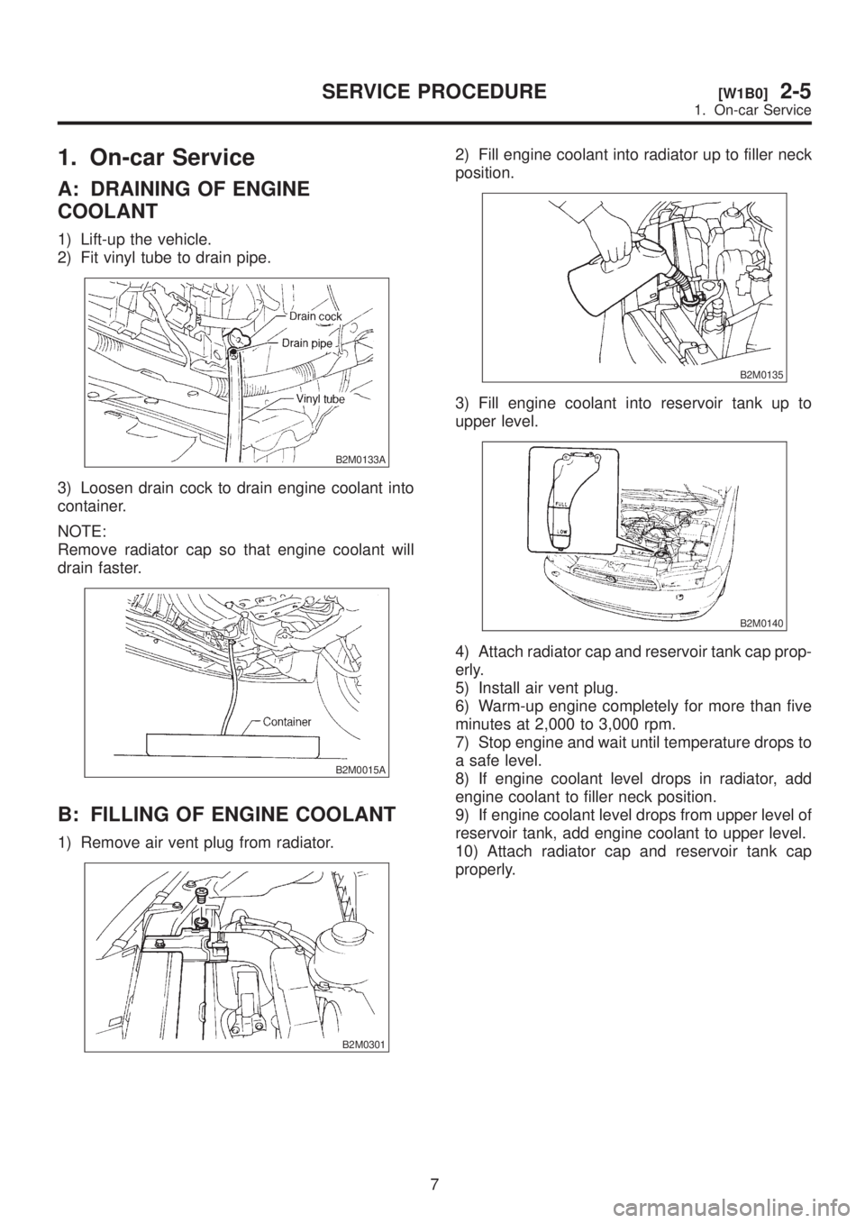
1. On-car Service
A: DRAINING OF ENGINE
COOLANT
1) Lift-up the vehicle.
2) Fit vinyl tube to drain pipe.
B2M0133A
3) Loosen drain cock to drain engine coolant into
container.
NOTE:
Remove radiator cap so that engine coolant will
drain faster.
B2M0015A
B: FILLING OF ENGINE COOLANT
1) Remove air vent plug from radiator.
B2M0301
2) Fill engine coolant into radiator up to filler neck
position.
B2M0135
3) Fill engine coolant into reservoir tank up to
upper level.
B2M0140
4) Attach radiator cap and reservoir tank cap prop-
erly.
5) Install air vent plug.
6) Warm-up engine completely for more than five
minutes at 2,000 to 3,000 rpm.
7) Stop engine and wait until temperature drops to
a safe level.
8) If engine coolant level drops in radiator, add
engine coolant to filler neck position.
9) If engine coolant level drops from upper level of
reservoir tank, add engine coolant to upper level.
10) Attach radiator cap and reservoir tank cap
properly.
7
[W1B0]2-5SERVICE PROCEDURE
1. On-car Service
Page 568 of 1456

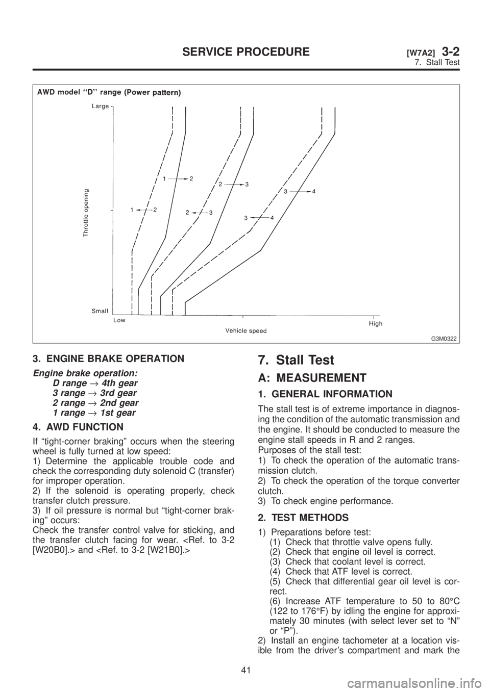
G3M0322
3. ENGINE BRAKE OPERATION
Engine brake operation:
D range
®4th gear
3 range
®3rd gear
2 range
®2nd gear
1 range
®1st gear
4. AWD FUNCTION
If ªtight-corner brakingº occurs when the steering
wheel is fully turned at low speed:
1) Determine the applicable trouble code and
check the corresponding duty solenoid C (transfer)
for improper operation.
2) If the solenoid is operating properly, check
transfer clutch pressure.
3) If oil pressure is normal but ªtight-corner brak-
ingº occurs:
Check the transfer control valve for sticking, and
the transfer clutch facing for wear.
[W20B0].> and
7. Stall Test
A: MEASUREMENT
1. GENERAL INFORMATION
The stall test is of extreme importance in diagnos-
ing the condition of the automatic transmission and
the engine. It should be conducted to measure the
engine stall speeds in R and 2 ranges.
Purposes of the stall test:
1) To check the operation of the automatic trans-
mission clutch.
2) To check the operation of the torque converter
clutch.
3) To check engine performance.
2. TEST METHODS
1) Preparations before test:
(1) Check that throttle valve opens fully.
(2) Check that engine oil level is correct.
(3) Check that coolant level is correct.
(4) Check that ATF level is correct.
(5) Check that differential gear oil level is cor-
rect.
(6) Increase ATF temperature to 50 to 80ÉC
(122 to 176ÉF) by idling the engine for approxi-
mately 30 minutes (with select lever set to ªNº
or ªPº).
2) Install an engine tachometer at a location vis-
ible from the driver's compartment and mark the
41
[W7A2]3-2SERVICE PROCEDURE
7. Stall Test
Page 569 of 1456

G3M0322
3. ENGINE BRAKE OPERATION
Engine brake operation:
D range
®4th gear
3 range
®3rd gear
2 range
®2nd gear
1 range
®1st gear
4. AWD FUNCTION
If ªtight-corner brakingº occurs when the steering
wheel is fully turned at low speed:
1) Determine the applicable trouble code and
check the corresponding duty solenoid C (transfer)
for improper operation.
2) If the solenoid is operating properly, check
transfer clutch pressure.
3) If oil pressure is normal but ªtight-corner brak-
ingº occurs:
Check the transfer control valve for sticking, and
the transfer clutch facing for wear.
[W20B0].> and
7. Stall Test
A: MEASUREMENT
1. GENERAL INFORMATION
The stall test is of extreme importance in diagnos-
ing the condition of the automatic transmission and
the engine. It should be conducted to measure the
engine stall speeds in R and 2 ranges.
Purposes of the stall test:
1) To check the operation of the automatic trans-
mission clutch.
2) To check the operation of the torque converter
clutch.
3) To check engine performance.
2. TEST METHODS
1) Preparations before test:
(1) Check that throttle valve opens fully.
(2) Check that engine oil level is correct.
(3) Check that coolant level is correct.
(4) Check that ATF level is correct.
(5) Check that differential gear oil level is cor-
rect.
(6) Increase ATF temperature to 50 to 80ÉC
(122 to 176ÉF) by idling the engine for approxi-
mately 30 minutes (with select lever set to ªNº
or ªPº).
2) Install an engine tachometer at a location vis-
ible from the driver's compartment and mark the
41
[W7A2]3-2SERVICE PROCEDURE
7. Stall Test