1999 SUBARU LEGACY charging
[x] Cancel search: chargingPage 127 of 1456

1. Engine Trouble in General
NOTE:
ªRANKº shown in the chart refer to the possibility of reason for the trouble in order (ªVery oftenº to ªRarelyº)
A Ð Very often
B Ð Sometimes
C Ð Rarely
TROUBLE PROBLEM PARTS, ETC. POSSIBLE CAUSE RANK
1. Engine will not start.
1) Starter does not turn.IStarterIDefective battery-to-starter harness B
IDefective starter switch C
IDefective inhibitor switch or neutral switch C
IDefective starter B
IBatteryIPoor terminal connecton A
IRun-down battrey A
IDefective charging system B
IFrictionISeizure of crankshaft and connecting rod bearing C
ISeized camshaft C
ISeized or stuck piston and cylinder C
2) Initial combustion does
not occur.IStarterIDefective starter C
IFuel injection system
IFuel lineIDefective fuel pump and relay A
ILack of or insufficient fuel B
IBeltIDefective B
IDefective timing B
ICompressionIIncorrect valve clearance C
ILoosened spark plugs or defective gasket C
ILoosened cylinder head bolts or defective gasket C
IImproper valve seating C
IDefective valve stem C
IWorn or broken valve spring B
IWorn or stuck piston rings, cylinder and piston C
IIncorrect valve timing B
IImproper engine oil (low viscosity) B
3) Initial combustion occur.IFuel injection system
IIntake systemIDefective intake manifold gasket B
IDefective throttle body gasket B
IFuel lineIDefective fuel pump and relay C
IClogged fuel line C
ILack of or insufficient fuel B
IBeltIDefective B
IDefective timing B
ICompressionIIncorrect valve clearance C
ILoosened spark plugs or defective gasket C
ILoosened cylinder head bolts or defective gasket C
IImproper valve seating C
IDefective valve stem C
IWorn or broken valve spring B
IWorn or stuck piston rings, cylinder and piston C
IIncorrect valve timing B
IImproper engine oil (low viscosity) B
73
[K100]2-3aDIAGNOSTICS
1. Engine Trouble in General
Page 202 of 1456
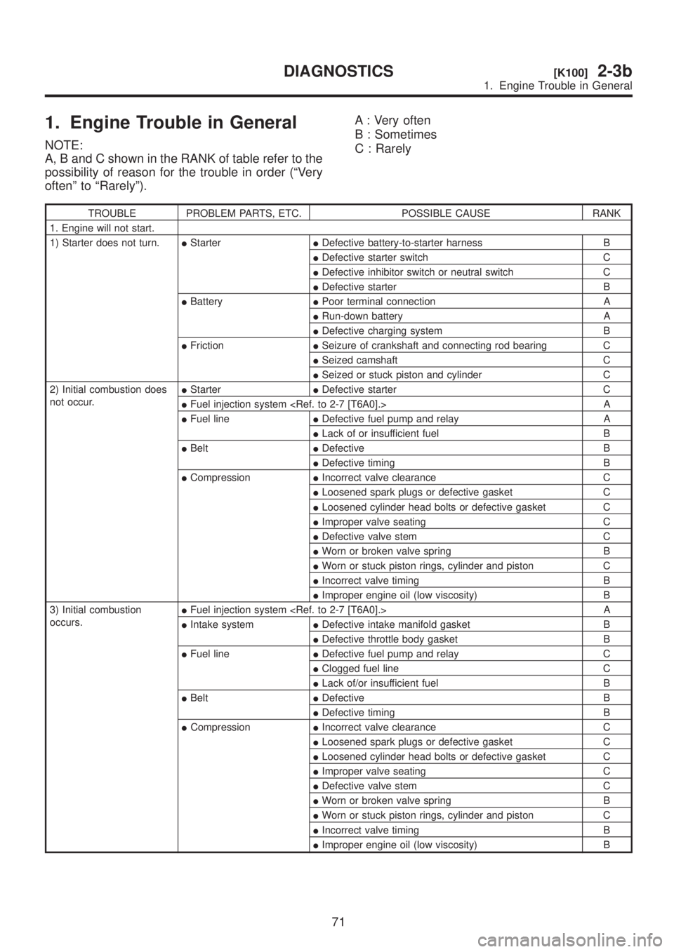
1. Engine Trouble in General
NOTE:
A, B and C shown in the RANK of table refer to the
possibility of reason for the trouble in order (ªVery
oftenº to ªRarelyº).A : Very often
B : Sometimes
C : Rarely
TROUBLE PROBLEM PARTS, ETC. POSSIBLE CAUSE RANK
1. Engine will not start.
1) Starter does not turn.IStarterIDefective battery-to-starter harness B
IDefective starter switch C
IDefective inhibitor switch or neutral switch C
IDefective starter B
IBatteryIPoor terminal connection A
IRun-down battery A
IDefective charging system B
IFrictionISeizure of crankshaft and connecting rod bearing C
ISeized camshaft C
ISeized or stuck piston and cylinder C
2) Initial combustion does
not occur.IStarterIDefective starter C
IFuel injection system
IFuel lineIDefective fuel pump and relay A
ILack of or insufficient fuel B
IBeltIDefective B
IDefective timing B
ICompressionIIncorrect valve clearance C
ILoosened spark plugs or defective gasket C
ILoosened cylinder head bolts or defective gasket C
IImproper valve seating C
IDefective valve stem C
IWorn or broken valve spring B
IWorn or stuck piston rings, cylinder and piston C
IIncorrect valve timing B
IImproper engine oil (low viscosity) B
3) Initial combustion
occurs.IFuel injection system
IIntake systemIDefective intake manifold gasket B
IDefective throttle body gasket B
IFuel lineIDefective fuel pump and relay C
IClogged fuel line C
ILack of/or insufficient fuel B
IBeltIDefective B
IDefective timing B
ICompressionIIncorrect valve clearance C
ILoosened spark plugs or defective gasket C
ILoosened cylinder head bolts or defective gasket C
IImproper valve seating C
IDefective valve stem C
IWorn or broken valve spring B
IWorn or stuck piston rings, cylinder and piston C
IIncorrect valve timing B
IImproper engine oil (low viscosity) B
71
[K100]2-3bDIAGNOSTICS
1. Engine Trouble in General
Page 986 of 1456
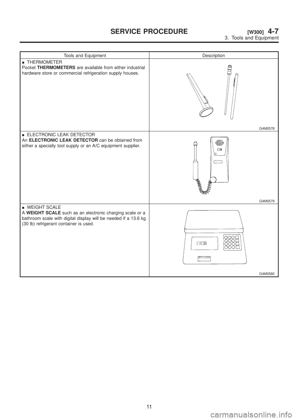
Tools and Equipment Description
ITHERMOMETER
PocketTHERMOMETERSare available from either industrial
hardware store or commercial refrigeration supply houses.
G4M0578
IELECTRONIC LEAK DETECTOR
AnELECTRONIC LEAK DETECTORcan be obtained from
either a specially tool supply or an A/C equipment supplier.
G4M0579
IWEIGHT SCALE
AWEIGHT SCALEsuch as an electronic charging scale or a
bathroom scale with digital display will be needed if a 13.6 kg
(30 lb) refrigerant container is used.
G4M0580
11
[W300]4-7SERVICE PROCEDURE
3. Tools and Equipment
Page 990 of 1456
6. Discharge the System
CAUTION:
The following points should be kept in mind
when discharging the system.
IBe certain that goggles and gloves are worn.
IConnect refrigerant recovery system to
manifold gauge set and remove recycle refrig-
erant from A/C system.
NOTE:
Refer to appropriate refrigerant recovery system
instruction manual for operation.
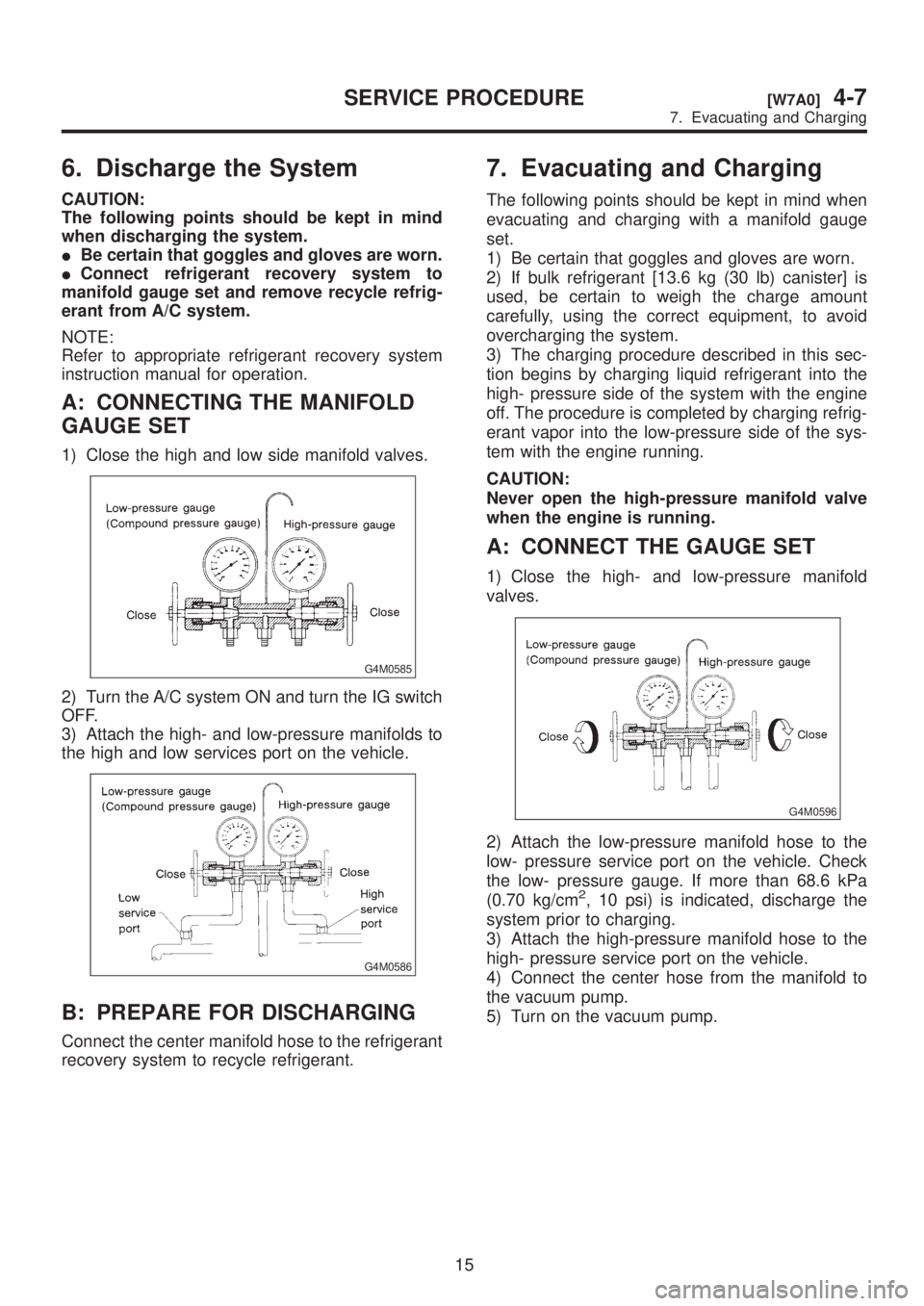
A: CONNECTING THE MANIFOLD
GAUGE SET
1) Close the high and low side manifold valves.
G4M0585
2) Turn the A/C system ON and turn the IG switch
OFF.
3) Attach the high- and low-pressure manifolds to
the high and low services port on the vehicle.
G4M0586
B: PREPARE FOR DISCHARGING
Connect the center manifold hose to the refrigerant
recovery system to recycle refrigerant.
7. Evacuating and Charging
The following points should be kept in mind when
evacuating and charging with a manifold gauge
set.
1) Be certain that goggles and gloves are worn.
2) If bulk refrigerant [13.6 kg (30 lb) canister] is
used, be certain to weigh the charge amount
carefully, using the correct equipment, to avoid
overcharging the system.
3) The charging procedure described in this sec-
tion begins by charging liquid refrigerant into the
high- pressure side of the system with the engine
off. The procedure is completed by charging refrig-
erant vapor into the low-pressure side of the sys-
tem with the engine running.
CAUTION:
Never open the high-pressure manifold valve
when the engine is running.
A: CONNECT THE GAUGE SET
1) Close the high- and low-pressure manifold
valves.
G4M0596
2) Attach the low-pressure manifold hose to the
low- pressure service port on the vehicle. Check
the low- pressure gauge. If more than 68.6 kPa
(0.70 kg/cm
2, 10 psi) is indicated, discharge the
system prior to charging.
3) Attach the high-pressure manifold hose to the
high- pressure service port on the vehicle.
4) Connect the center hose from the manifold to
the vacuum pump.
5) Turn on the vacuum pump.
15
[W7A0]4-7SERVICE PROCEDURE
7. Evacuating and Charging
Page 991 of 1456

6. Discharge the System
CAUTION:
The following points should be kept in mind
when discharging the system.
IBe certain that goggles and gloves are worn.
IConnect refrigerant recovery system to
manifold gauge set and remove recycle refrig-
erant from A/C system.
NOTE:
Refer to appropriate refrigerant recovery system
instruction manual for operation.
A: CONNECTING THE MANIFOLD
GAUGE SET
1) Close the high and low side manifold valves.
G4M0585
2) Turn the A/C system ON and turn the IG switch
OFF.
3) Attach the high- and low-pressure manifolds to
the high and low services port on the vehicle.
G4M0586
B: PREPARE FOR DISCHARGING
Connect the center manifold hose to the refrigerant
recovery system to recycle refrigerant.
7. Evacuating and Charging
The following points should be kept in mind when
evacuating and charging with a manifold gauge
set.
1) Be certain that goggles and gloves are worn.
2) If bulk refrigerant [13.6 kg (30 lb) canister] is
used, be certain to weigh the charge amount
carefully, using the correct equipment, to avoid
overcharging the system.
3) The charging procedure described in this sec-
tion begins by charging liquid refrigerant into the
high- pressure side of the system with the engine
off. The procedure is completed by charging refrig-
erant vapor into the low-pressure side of the sys-
tem with the engine running.
CAUTION:
Never open the high-pressure manifold valve
when the engine is running.
A: CONNECT THE GAUGE SET
1) Close the high- and low-pressure manifold
valves.
G4M0596
2) Attach the low-pressure manifold hose to the
low- pressure service port on the vehicle. Check
the low- pressure gauge. If more than 68.6 kPa
(0.70 kg/cm
2, 10 psi) is indicated, discharge the
system prior to charging.
3) Attach the high-pressure manifold hose to the
high- pressure service port on the vehicle.
4) Connect the center hose from the manifold to
the vacuum pump.
5) Turn on the vacuum pump.
15
[W7A0]4-7SERVICE PROCEDURE
7. Evacuating and Charging
Page 992 of 1456
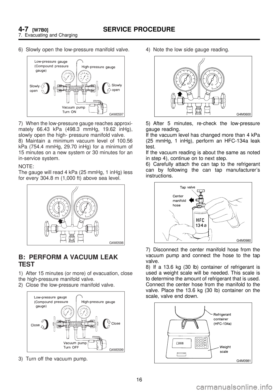
6) Slowly open the low-pressure manifold valve.
G4M0597
7) When the low-pressure gauge reaches approxi-
mately 66.43 kPa (498.3 mmHg, 19.62 inHg),
slowly open the high- pressure manifold valve.
8) Maintain a minimum vacuum level of 100.56
kPa (754.4 mmHg, 29.70 inHg) for a minimum of
15 minutes on a new system or 30 minutes for an
in-service system.
NOTE:
The gauge will read 4 kPa (25 mmHg, 1 inHg) less
for every 304.8 m (1,000 ft) above sea level.
G4M0598
B: PERFORM A VACUUM LEAK
TEST
1) After 15 minutes (or more) of evacuation, close
the high-pressure manifold valve.
2) Close the low-pressure manifold valve.
G4M0599
3) Turn off the vacuum pump.4) Note the low side gauge reading.
G4M0600
5) After 5 minutes, re-check the low-pressure
gauge reading.
If the vacuum level has changed more than 4 kPa
(25 mmHg, 1 inHg), perform an HFC-134a leak
test.
If the vacuum reading is about the same as noted
in step 4), continue on to next step.
6) Carefully attach the can tap to the refrigerant
can by following the can tap manufacturer's
instructions.
G4M0980
7) Disconnect the center manifold hose from the
vacuum pump and connect the hose to the tap
valve.
8) If a 13.6 kg (30 lb) container of refrigerant is
used a weight scale will be needed. This scale is
to determine the amount of refrigerant that is used.
Connect the center hose from the manifold to the
valve. Place the 13.6 kg (30 lb) container on the
scale, valve end down.
G4M0981
16
4-7[W7B0]SERVICE PROCEDURE
7. Evacuating and Charging
Page 993 of 1456
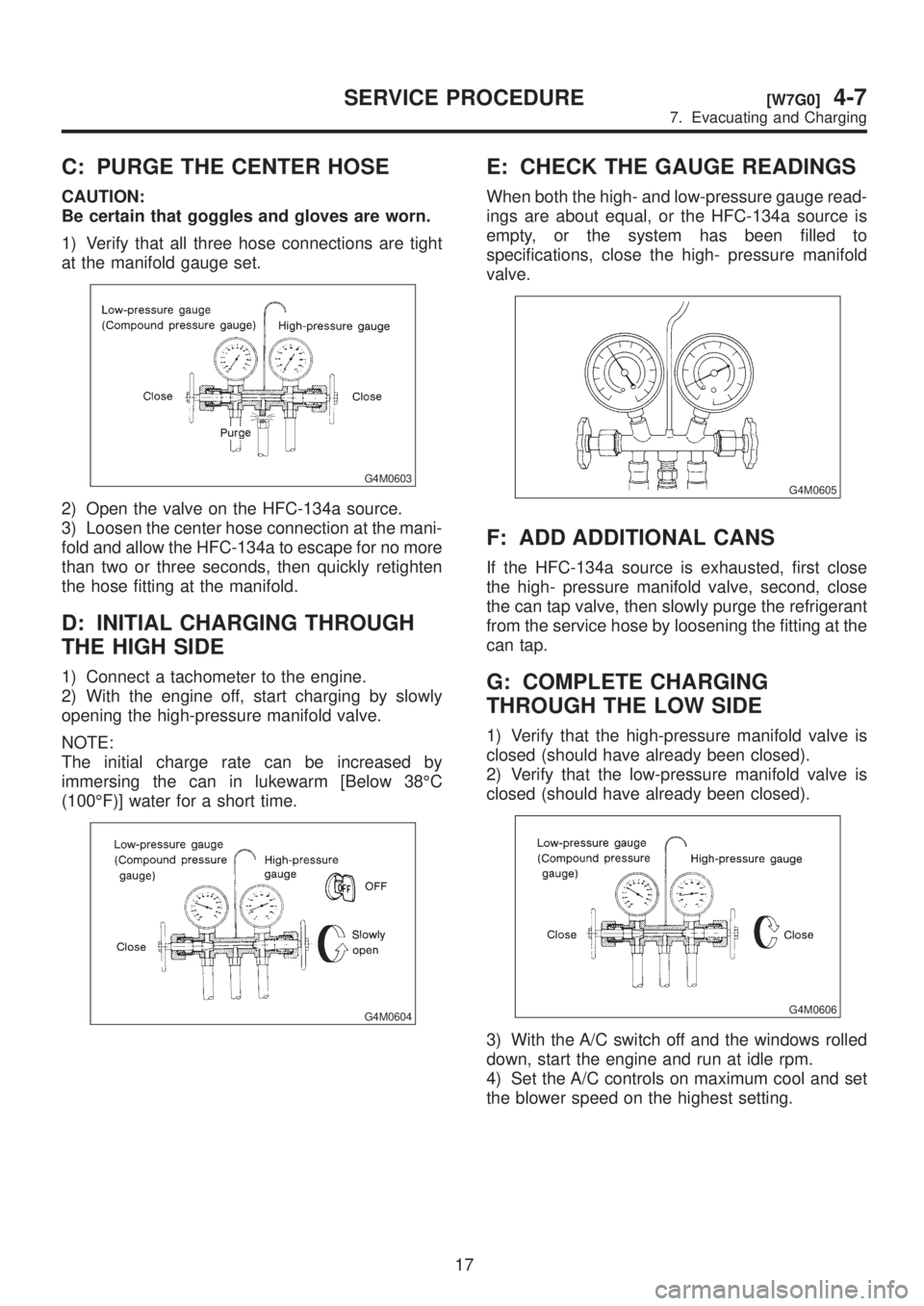
C: PURGE THE CENTER HOSE
CAUTION:
Be certain that goggles and gloves are worn.
1) Verify that all three hose connections are tight
at the manifold gauge set.
G4M0603
2) Open the valve on the HFC-134a source.
3) Loosen the center hose connection at the mani-
fold and allow the HFC-134a to escape for no more
than two or three seconds, then quickly retighten
the hose fitting at the manifold.
D: INITIAL CHARGING THROUGH
THE HIGH SIDE
1) Connect a tachometer to the engine.
2) With the engine off, start charging by slowly
opening the high-pressure manifold valve.
NOTE:
The initial charge rate can be increased by
immersing the can in lukewarm [Below 38ÉC
(100ÉF)] water for a short time.
G4M0604
E: CHECK THE GAUGE READINGS
When both the high- and low-pressure gauge read-
ings are about equal, or the HFC-134a source is
empty, or the system has been filled to
specifications, close the high- pressure manifold
valve.
G4M0605
F: ADD ADDITIONAL CANS
If the HFC-134a source is exhausted, first close
the high- pressure manifold valve, second, close
the can tap valve, then slowly purge the refrigerant
from the service hose by loosening the fitting at the
can tap.
G: COMPLETE CHARGING
THROUGH THE LOW SIDE
1) Verify that the high-pressure manifold valve is
closed (should have already been closed).
2) Verify that the low-pressure manifold valve is
closed (should have already been closed).
G4M0606
3) With the A/C switch off and the windows rolled
down, start the engine and run at idle rpm.
4) Set the A/C controls on maximum cool and set
the blower speed on the highest setting.
17
[W7G0]4-7SERVICE PROCEDURE
7. Evacuating and Charging
Page 994 of 1456

5) Quickly turn the A/C switch on-off-on-off a few
times to prevent initial compressor damage due to
ªload shock.º Finish this operation with the A/C
switch in the ON position.
G4M0607
6) Raise engine rpm to approximately 1,500 rpm.
H: CHARGE THE SYSTEM
1) With the refrigerant source connected and the
service hose purged, slowly open the low-pressure
manifold valve, while checking the low-pressure
gauge reading.
CAUTION:
The refrigerant source must be positioned for
vapor (valve up).
G4M0608
2) Keep the low side pressure below 276 kPa
(2.81 kg/cm2, 40 psi) by using the low-pressure
manifold valve to regulate the flow of refrigerant
into the system.
3) When the system is fully charged, close the
low- pressure manifold valve.
4) Close the valve at the refrigerant source.
IRefrigerant capacity
Unit: kg (lb)
Refrigerant Minimum Maximum
HFC-134a 0.55 (1.21) 0.65 (1.43)
I: COMPLETE ALL SYSTEM
CHECKS
1) Evaluate the system performance.
CAUTION:
IAlways perform leak checking in an environ-
ment free of refrigerant pollution.
IDo not disconnect the high- or low-pressure
hoses from the vehicle before leak checking.
J: DISCONNECT THE MANIFOLD
GAUGE SET
Remove the high- or low-pressure hoses from the
service ports and install the service port caps.
18
4-7[W7H0]SERVICE PROCEDURE
7. Evacuating and Charging