Page 705 of 1456

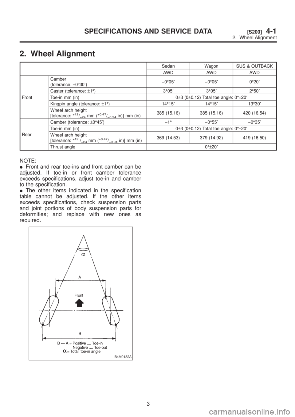
2. Wheel Alignment
Sedan Wagon SUS & OUTBACK
AWD AWD AWD
FrontCamber
(tolerance:±0É30¢)þ0É05¢þ0É05¢0É20¢
Caster (tolerance:±1É) 3É05¢3É05¢2É50¢
Toe-in mm (in) 0±3(0±0.12) Total toe angle: 0ɱ20¢
Kingpin angle (tolerance:±1É) 14É15¢14É15¢13É30¢
Wheel arch height
[tolerance:
+12/þ24mm (+0.47/þ0.94in)] mm (in)385 (15.16) 385 (15.16) 420 (16.54)
RearCamber (tolerance:±0É45¢) þ1É þ0É55¢þ0É35¢
Toe-in mm (in) 0±3(0±0.12) Total toe angle: 0ɱ20¢
Wheel arch height
[tolerance:
+12/þ24mm (+0.47/þ0.94in)] mm (in)369 (14.53) 379 (14.92) 419 (16.50)
Thrust angle 0ɱ20¢
NOTE:
IFront and rear toe-ins and front camber can be
adjusted. If toe-in or front camber tolerance
exceeds specifications, adjust toe-in and camber
to the specification.
IThe other items indicated in the specification
table cannot be adjusted. If the other items
exceeds specifications, check suspension parts
and joint portions of body suspension parts for
deformities; and replace with new ones as
required.
B4M0182A
3
[S200]4-1SPECIFICATIONS AND SERVICE DATA
2. Wheel Alignment
Page 706 of 1456
1. Front Suspension
B4M1148B
(1) Front crossmember
(2) Bolt ASSY
(3) Housing
(4) Washer
(5) Stopper rubber (Rear)
(6) Rear bushing
(7) Stopper rubber (Front)
(8) Ball joint
(9) Transverse link
(10) Cotter pin
(11) Front bushing
(12) Stabilizer link
(13) Clamp (2200 cc model)
(14) Bushing (2200 cc model)
(15) Stabilizer
(16) Jack-up plate (Except 2500 cc
MT model)(17) Dust seal
(18) Strut mount
(19) Spacer
(20) Upper spring seat
(21) Rubber seat
(22) Dust cover
(23) Helper
(24) Coil spring
(25) Damper strut
(26) Adjusting bolt
(27) Castle nut
(28) Self-locking nut
(29) Adapter front crossmember
(SUS & OUTBACK model)
(30) Clip (SUS & OUTBACK model)
(31) Bushing (2500 cc model)
(32) Clamp (2500 cc model)(33) Dynamic damper (2500 cc MT
model)
(34) Jack-up plate (2500 cc MT
model)
4
4-1[C100]COMPONENT PARTS
1. Front Suspension
Page 708 of 1456

2. Rear Suspension
B4M0766B
(1) Stabilizer
(2) Stabilizer bracket
(3) Stabilizer bushing
(4) Clamp
(5) Floating bushing
(6) Stopper
(7) Stabilizer link
(8) Rear lateral link
(9) Bushing (C)
(10) Bushing (A)
(11) Front lateral link
(12) Bushing (B)
(13) Trailing link rear bushing
(14) Trailing link
(15) Trailing link front bushing
(16) Trailing link bracket(17) Cap (Protection)
(18) Washer
(19) Rear crossmember
(20) Strut mount cap
(21) Strut mount
(22) Rubber seat upper
(23) Dust cover
(24) Coil spring
(25) Helper
(26) Rubber seat lower
(27) Damper strut
(28) Self-locking nut
(29) Crossmember reinforcement
lower (Sedan model and except
SUS model)(30) Adapter rear crossmember (SUS
& OUTBACK model)
Tightening torque: N´m (kg-m, ft-lb)
T1:
20±6 (2.0±0.6, 14.5±4.3)
T2:25±7 (2.5±0.7, 18.1±5.1)
T3:44±6 (4.5±0.6, 32.5±4.3)
T4:59±10 (6.0±1.0, 43±7)
T5:98±15 (10.0±1.5, 72±11 )
T6:98±20 (10.0±2.0, 72±14)
T7:11 3±15 (11.5±1.5, 83±11 )
T8:127±20 (13.0±2.0, 94±14)
T9:137±20 (14.0±2.0, 101±14)
T10:196+39/þ10(20.0+4.0/þ1.0, 145+29/þ7)
6
4-1[C200]COMPONENT PARTS
2. Rear Suspension
Page 714 of 1456
6. THRUST ANGLE
IInspection
1) Position vehicle on a level surface.
2) Move vehicle 3 to 4 meters directly forward.
3) Determine locus of both front and rear axles.
4) Measure distance ªLº between center line of
loci of the axles.
Thrust angle:
Less than 20
¢when ªLº is equal to or
less than 15 mm (0.59 in).
G4M0488
IAdjustment
1) Make thrust angle adjustments by turning toe-in
adjusting bolts of rear suspension equally in the
same direction.
2) When one rear wheel is adjusted in a toe-in
direction, adjust the other rear wheel equally in
toe-out direction, in order to make thrust angle
adjustment.
3) When left and right adjusting bolts are turned
incrementally by one graduation in the same
direction, the thrust angle will change approxi-
mately 10' [ªLº is almost equal to 7.5 mm (0.295
in)].
Thrust angle:
0É
±20¢
G4M0488
12
4-1[W1B6]SERVICE PROCEDURE
1. On-car Services
Page 1030 of 1456
C: UNDERBODY
B5M0190B
(10) Radiator panel (LWR) frame
gauge hole 10 mm (0.39 in) dia.
(11) Front side frame front lower sur-
face 20 mm (0.79 in) dia.
(12) Front side frame center lower
surface 20 mm (0.79 in) dia.
(13) Front suspension attaching hole
M14
(14) Suspension attaching bracket
M14(15) Front side frame rear lower cen-
ter surface 20 mm (0.79 in) dia.
(16) Transmission mount attaching
hole M10
(17) Front side frame rear lower sur-
face 15 mm (0.59 in) dia.
(18) Rear frame front M12
(19) Rear frame front hole 25 mm
(0.98 in) dia.(20) Rear crossmember attaching
hole M12
(21) Rear frame center hole 7 mm
(0.28 in) dia.
(22) Rear frame rear concave part 15
mm (0.59 in) dia.
7
[S2C0]5-1SPECIFICATIONS AND SERVICE DATA
2. Body Datum Points