Page 755 of 1456
11) Using a puller, remove tie-rod ball joint from
knuckle arm.
G4M0219
12) On ABS equipped models, remove ABS sen-
sor assembly and harness in advance.
H4M1138A
13) Remove transverse link ball joint from hous-
ing.
G4M0221
14) After scribing an alignment mark on camber
adjusting bolt head, remove bolts which connect
housing and strut, and disconnect housing from
strut.
G4M0222
B: DISASSEMBLY
1) Using ST1, support housing and hub securely.
2) Attach ST2 to housing and drive hub out.
ST1 927080000 HUB STAND
ST2 927060000 HUB REMOVER
G4M0223
If inner bearing race remains in the hub, remove it
with a suitable tool (commercially available).
CAUTION:
IBe careful not to scratch polished area of
hub.
IBe sure to install inner race on the side of
outer race from which it was removed.
G4M0224
10
4-2[W1B0]SERVICE PROCEDURE
1. Front Axle
Page 758 of 1456

12) Attach hub to ST1 securely.
13) Clean dust or foreign particles from the pol-
ished surface of hub.
14) sing ST2, press bearing into hub by driving
inner race.
ST1 927080000 HUB STAND
ST2 927120000 HUB INSTALLER
G4M0235
E: INSTALLATION
1) Install transverse link ball joint to housing.
Tightening torque:
44
±6 N´m (4.5±0.6 kg-m, 32.5±4.3 ft-lb)
2) While aligning alignment mark on camber
adjusting bolt head, connect housing and strut.
CAUTION:
Use a new self-locking nut.
Tightening torque:
147
±15 N´m (15±1.5 kg-m, 108±11 ft-lb)
3) Install speed sensor and harness on housing
(only vehicle equipped with ABS).
4) Install disc rotor on hub.
5) Install disc brake caliper on housing.
Tightening torque:
59
±10 N´m (6±1 kg-m, 43±7 ft-lb)
6) Install front drive shaft.
7) Connect stabilizer link.8) Install tie-rod end ball joint on housing knuckle
arm.
Tightening torque:
27.0
±2.5 N´m (2.75±0.25 kg-m, 19.9±1.8
ft-lb)
G4M0236
9) While depressing brake pedal, tighten axle nut
and lock it securely.
CAUTION:
IUse a new axle nut.
IAlways tighten axle nut before installing
wheel on vehicle. If wheel is installed and
comes in contact with ground when axle nut is
loose, wheel bearings may be damaged.
IBe sure to tighten axle nut to specified
torque. Do not overtighten it as this may dam-
age wheel bearing.
Tightening torque:
186
±20 N´m (19±2 kg-m, 137±14 ft-lb)
G4M0237
10) After tightening axle nut, lock it securely.
G4M0238
13
[W1E0]4-2SERVICE PROCEDURE
1. Front Axle
Page 796 of 1456
2. Power Steering System
A: LHD MODEL
B4M1149B
(1) Clamp
(2) Adapter
(3) Hose bracket
(4) Pipe C
(5) Pipe D
(6) Clamp E
(7) Cap
(8) Strainer
(9) Seal washer
(10) Tank
(11) O-ring
(12) Oil pump
(13) Pulley
(14) Bracket
(15) Bush(16) Belt cover
(17) Clamp plate
(18) Pipe F
(19) Pipe E
(20) Universal joint
(21) Dust seal
(22) C-ring
(23) Oil seal
(24) Valve housing
(25) Packing
(26) Seal ring
(27) Pinion and valve ASSY
(28) Oil seal
(29) Back-up washer
(30) Ball bearing(31) Snap ring
(32) Lock nut
(33) Adjusting screw
(34) Spring
(35) Sleeve
(36) Adapter
(37) Clamp
(38) Cotter pin
(39) Castle nut
(40) Dust seal
(41) Clip
(42) Tie-rod end
(43) Small clip
(44) Boot
(45) Large clip
5
[C2A0]4-3COMPONENT PARTS
2. Power Steering System
Page 798 of 1456
B: RHD MODEL
B4M1150B
(1) Clamp
(2) Adapter
(3) Hose bracket
(4) Pipe C
(5) Pipe D
(6) Clamp E
(7) Cap
(8) Strainer
(9) Seal washer
(10) Tank
(11) O-ring
(12) Oil pump
(13) Pulley
(14) Bracket
(15) Bush
(16) Belt cover
(17) Universal joint(18) Dust cover
(19) Valve housing
(20) Y-packing
(21) Ball bearing
(22) Spacer
(23) Pinion
(24) Shim
(25) Adapter
(26) Clamp
(27) Castle nut
(28) Cotter pin
(29) Dust seal
(30) Clip
(31) Tie-rod end
(32) Clip
(33) Boot
(34) Wire(35) Tie-rod
(36) Lock washer
(37) Holder
(38) Bush
(39) Y-packing
(40) Oil seal
(41) O-ring
(42) Rack
(43) Oil seal
(44) Back-up washer
(45) Housing ASSY
(46) Pipe A
(47) Pipe B
(48) Lock nut
(49) Adjusting screw
(50) Spring
(51) Sleeve
7
[C2B0]4-3COMPONENT PARTS
2. Power Steering System
Page 805 of 1456

CAUTION:
Insert roll connector guide pin into guide hole
on lower end of surface of steering wheel to
prevent damage.
Draw out airbag system connector, horn con-
nector and cruise control connectors from
guide hole of steering wheel lower end. (with
airbag model)
8) Install airbag module to steering wheel. (with
airbag model)
WARNING:
Always refer to 5-5 Supplemental Restraint
System before performing the service opera-
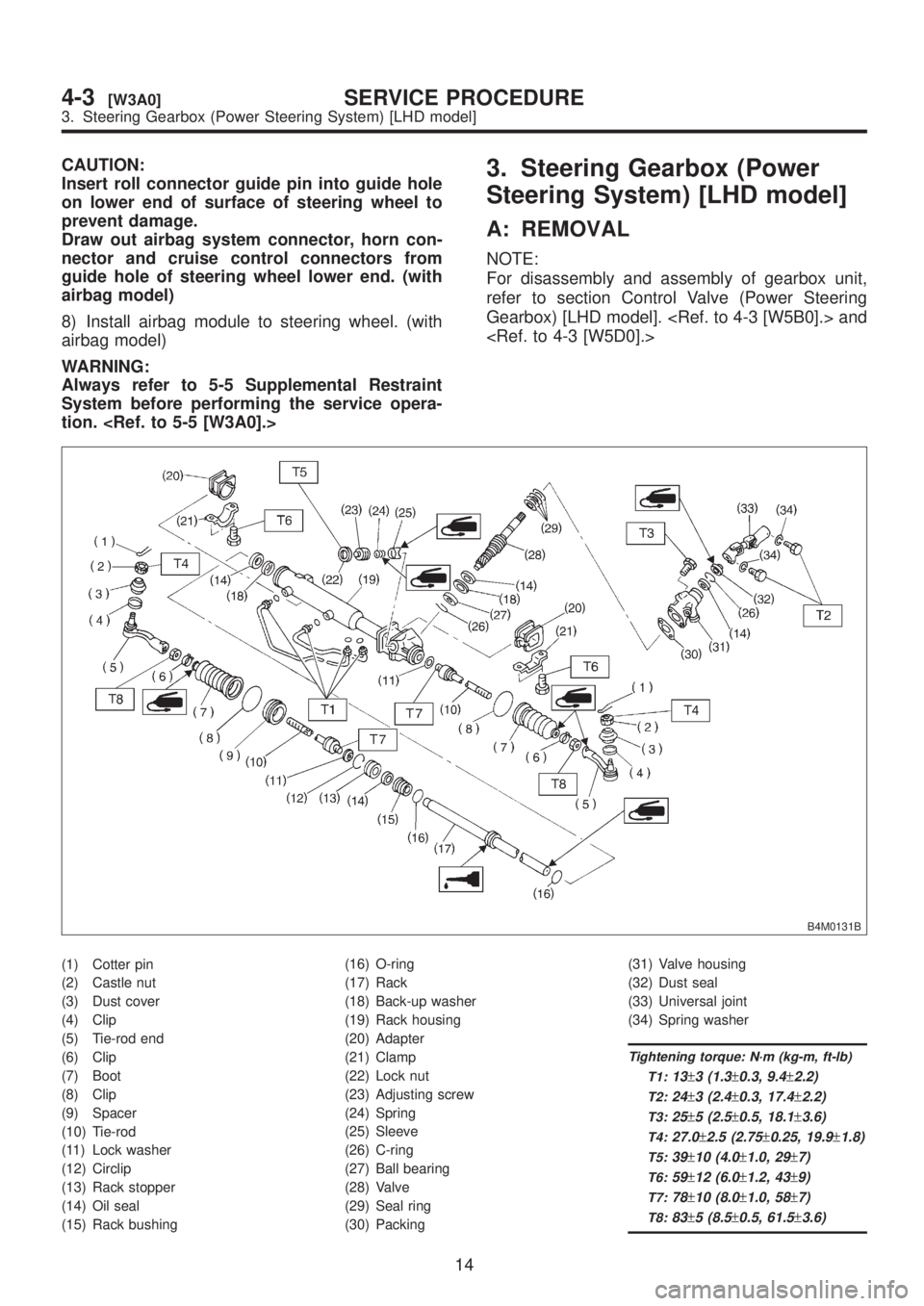
tion. 3. Steering Gearbox (Power
Steering System) [LHD model]
A: REMOVAL
NOTE:
For disassembly and assembly of gearbox unit,
refer to section Control Valve (Power Steering
Gearbox) [LHD model]. and
B4M0131B
(1) Cotter pin
(2) Castle nut
(3) Dust cover
(4) Clip
(5) Tie-rod end
(6) Clip
(7) Boot
(8) Clip
(9) Spacer
(10) Tie-rod
(11) Lock washer
(12) Circlip
(13) Rack stopper
(14) Oil seal
(15) Rack bushing(16) O-ring
(17) Rack
(18) Back-up washer
(19) Rack housing
(20) Adapter
(21) Clamp
(22) Lock nut
(23) Adjusting screw
(24) Spring
(25) Sleeve
(26) C-ring
(27) Ball bearing
(28) Valve
(29) Seal ring
(30) Packing(31) Valve housing
(32) Dust seal
(33) Universal joint
(34) Spring washer
Tightening torque: N´m (kg-m, ft-lb)
T1:
13±3 (1.3±0.3, 9.4±2.2)
T2:24±3 (2.4±0.3, 17.4±2.2)
T3:25±5 (2.5±0.5, 18.1±3.6)
T4:27.0±2.5 (2.75±0.25, 19.9±1.8)
T5:39±10 (4.0±1.0, 29±7)
T6:59±12 (6.0±1.2, 43±9)
T7:78±10 (8.0±1.0, 58±7)
T8:83±5 (8.5±0.5, 61.5±3.6)
14
4-3[W3A0]SERVICE PROCEDURE
3. Steering Gearbox (Power Steering System) [LHD model]
Page 806 of 1456

CAUTION:
Insert roll connector guide pin into guide hole
on lower end of surface of steering wheel to
prevent damage.
Draw out airbag system connector, horn con-
nector and cruise control connectors from
guide hole of steering wheel lower end. (with
airbag model)
8) Install airbag module to steering wheel. (with
airbag model)
WARNING:
Always refer to 5-5 Supplemental Restraint
System before performing the service opera-
tion. 3. Steering Gearbox (Power
Steering System) [LHD model]
A: REMOVAL
NOTE:
For disassembly and assembly of gearbox unit,
refer to section Control Valve (Power Steering
Gearbox) [LHD model]. and
B4M0131B
(1) Cotter pin
(2) Castle nut
(3) Dust cover
(4) Clip
(5) Tie-rod end
(6) Clip
(7) Boot
(8) Clip
(9) Spacer
(10) Tie-rod
(11) Lock washer
(12) Circlip
(13) Rack stopper
(14) Oil seal
(15) Rack bushing(16) O-ring
(17) Rack
(18) Back-up washer
(19) Rack housing
(20) Adapter
(21) Clamp
(22) Lock nut
(23) Adjusting screw
(24) Spring
(25) Sleeve
(26) C-ring
(27) Ball bearing
(28) Valve
(29) Seal ring
(30) Packing(31) Valve housing
(32) Dust seal
(33) Universal joint
(34) Spring washer
Tightening torque: N´m (kg-m, ft-lb)
T1:
13±3 (1.3±0.3, 9.4±2.2)
T2:24±3 (2.4±0.3, 17.4±2.2)
T3:25±5 (2.5±0.5, 18.1±3.6)
T4:27.0±2.5 (2.75±0.25, 19.9±1.8)
T5:39±10 (4.0±1.0, 29±7)
T6:59±12 (6.0±1.2, 43±9)
T7:78±10 (8.0±1.0, 58±7)
T8:83±5 (8.5±0.5, 61.5±3.6)
14
4-3[W3A0]SERVICE PROCEDURE
3. Steering Gearbox (Power Steering System) [LHD model]
Page 808 of 1456

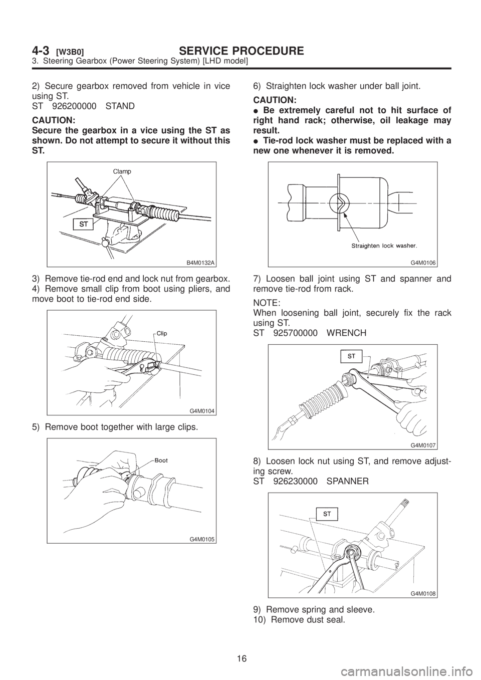
2) Secure gearbox removed from vehicle in vice
using ST.
ST 926200000 STAND
CAUTION:
Secure the gearbox in a vice using the ST as
shown. Do not attempt to secure it without this
ST.
B4M0132A
3) Remove tie-rod end and lock nut from gearbox.
4) Remove small clip from boot using pliers, and
move boot to tie-rod end side.
G4M0104
5) Remove boot together with large clips.
G4M0105
6) Straighten lock washer under ball joint.
CAUTION:
IBe extremely careful not to hit surface of
right hand rack; otherwise, oil leakage may
result.
ITie-rod lock washer must be replaced with a
new one whenever it is removed.
G4M0106
7) Loosen ball joint using ST and spanner and
remove tie-rod from rack.
NOTE:
When loosening ball joint, securely fix the rack
using ST.
ST 925700000 WRENCH
G4M0107
8) Loosen lock nut using ST, and remove adjust-
ing screw.
ST 926230000 SPANNER
G4M0108
9) Remove spring and sleeve.
10) Remove dust seal.
16
4-3[W3B0]SERVICE PROCEDURE
3. Steering Gearbox (Power Steering System) [LHD model]
Page 809 of 1456

CAUTION:
Be careful not to damage housing and input
shaft, or to allow foreign matters to get inside
when removing dust seal.
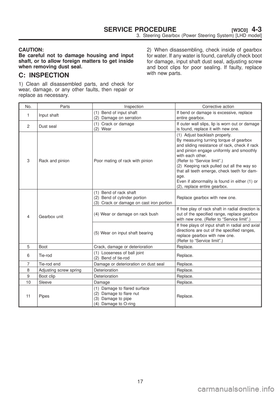
C: INSPECTION
1) Clean all disassembled parts, and check for
wear, damage, or any other faults, then repair or
replace as necessary.2) When disassembling, check inside of gearbox
for water. If any water is found, carefully check boot
for damage, input shaft dust seal, adjusting screw
and boot clips for poor sealing. If faulty, replace
with new parts.
No. Parts Inspection Corrective action
1 Input shaft(1) Bend of input shaft
(2) Damage on serrationIf bend or damage is excessive, replace
entire gearbox.
2 Dust seal(1) Crack or damage
(2) WearIf outer wall slips, lip is worn out or damage
is found, replace it with new one.
3 Rack and pinion Poor mating of rack with pinion(1) Adjust backlash properly.
By measuring turning torque of gearbox
and sliding resistance of rack, check if rack
and pinion engage uniformly and smoothly
with each other.
(Refer to ªService limitº.)
(2) Keeping rack pulled out all the way so
that all teeth emerge, check teeth for dam-
age.
Even if abnormality is found in either (1) or
(2), replace entire gearbox.
4 Gearbox unit(1) Bend of rack shaft
(2) Bend of cylinder portion
(3) Crack or damage on cast iron portionReplace gearbox with new one.
(4) Wear or damage on rack bushIf free play of rack shaft in radial direction is
out of the specified range, replace gearbox
with new one. (Refer to ªService limitº.)
(5) Wear on input shaft bearingIf free plays of input shaft in radial and axial
directions are out of the specified ranges,
replace gearbox with new one.
(Refer to ªService limitº.)
5 Boot Crack, damage or deterioration Replace.
6 Tie-rod(1) Looseness of ball joint
(2) Bend of tie-rodReplace.
7 Tie-rod end Damage or deterioration on dust seal Replace.
8 Adjusting screw spring Deterioration Replace.
9 Boot clip Deterioration Replace.
10 Sleeve Damage Replace.
11 Pipes(1) Damage to flared surface
(2) Damage to flare nut
(3) Damage to pipe
(4) Damage to O-ringReplace.
17
[W3C0]4-3SERVICE PROCEDURE
3. Steering Gearbox (Power Steering System) [LHD model]