Page 491 of 1456

3) Inspection and adjustment of ST
NOTE:
ILoosen the two bolts and adjust so that the scale
indicates 0.5 correctly when the plate end and the
scale end are on the same level.
ITighten the two bolts.
ST 499917500 DRIVE PINION GAUGE ASSY
B3M0064B
(A) Plate
(B) Scale
4) Position the ST by inserting the knock pin of ST
into the knock hole in the transmission case.
ST 499917500 DRIVE PINION GAUGE ASSY
5) Slide the drive pinion gauge scale with finger tip
and read the value at the point where it matches
with the end face of drive pinion.
ST 499917500 DRIVE PINION GAUGE ASSY
B3M0065C
(A) Adjust clearance to zero without shim.
6) The thickness of shim shall be determined by
adding the value indicated on drive pinion to the
value indicated on the ST. (Add if the number on
drive pinion is prefixed by + and subtract if the
number is prefixed by þ.)
ST 499917500 DRIVE PINION GAUGE ASSY7) Select one to three shims from the next table for
the value determined as described above and take
a shim thickness which is closest to the said value.
Drive pinion shim
Part No. Thickness mm (in)
32295AA031 0.150 (0.0059)
32295AA041 0.175 (0.0069)
32295AA051 0.200 (0.0079)
32295AA061 0.225 (0.0089)
32295AA071 0.250 (0.0098)
32295AA081 0.275 (0.0108)
32295AA091 0.300 (0.0118)
32295AA101 0.500 (0.0197)
8) Install differential assembly on left hand trans-
mission case.
CAUTION:
Be careful not to fold the sealing lip of oil seal.
NOTE:
Wrap the left and right splined sections of axle
shaft with vinyl tape to prevent scratches.
G3M0557
9) Install needle bearing and oil seal onto the front
of transmission main shaft assembly, and position
in left side transmission case.
CAUTION:
IWrap clutch splined section with vinyl tape
to prevent damage to oil seal.
IApply grease (Unilube #2 or equivalent) to
the sealing lip of oil seal.
IUse a new oil seal.
23
[W2B2]3-1SERVICE PROCEDURE
2. Transmission Case
Page 997 of 1456

7. CHECK THE EVAPORATOR
ASSEMBLY
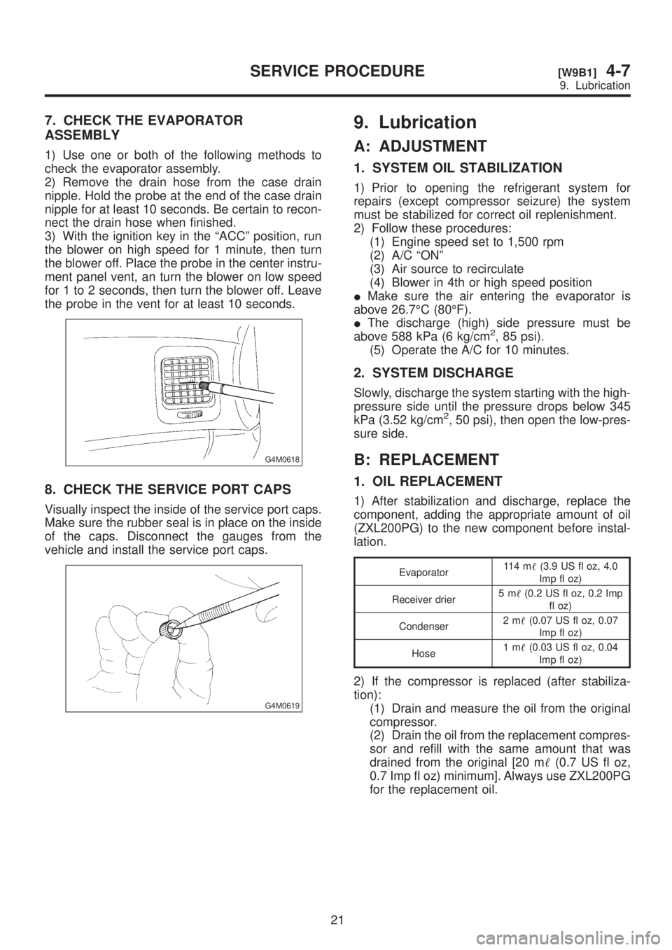
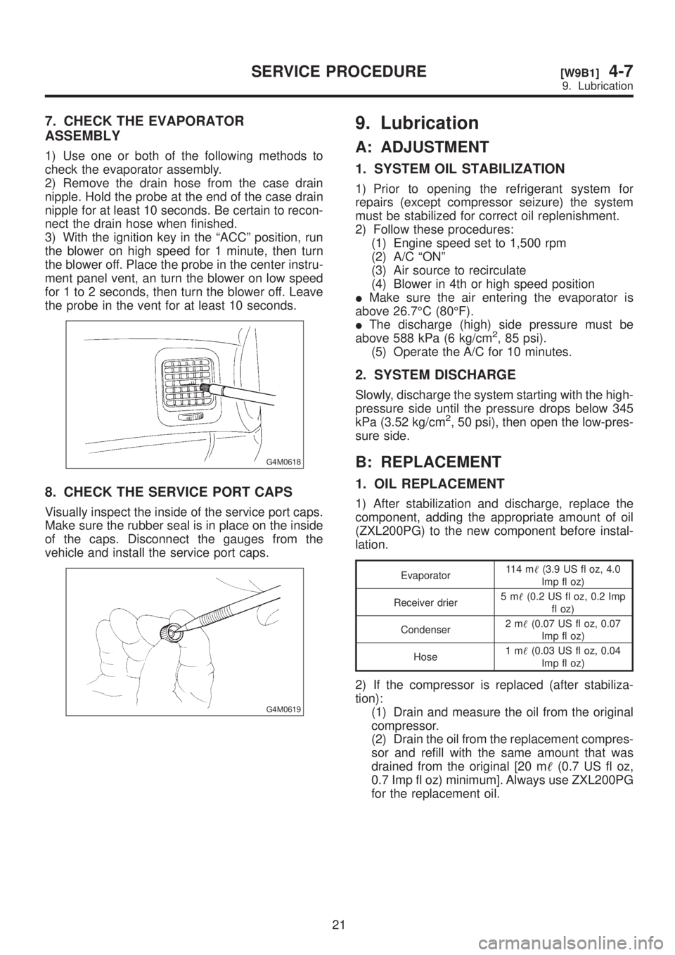
1) Use one or both of the following methods to
check the evaporator assembly.
2) Remove the drain hose from the case drain
nipple. Hold the probe at the end of the case drain
nipple for at least 10 seconds. Be certain to recon-
nect the drain hose when finished.
3) With the ignition key in the ªACCº position, run
the blower on high speed for 1 minute, then turn
the blower off. Place the probe in the center instru-
ment panel vent, an turn the blower on low speed
for 1 to 2 seconds, then turn the blower off. Leave
the probe in the vent for at least 10 seconds.
G4M0618
8. CHECK THE SERVICE PORT CAPS
Visually inspect the inside of the service port caps.
Make sure the rubber seal is in place on the inside
of the caps. Disconnect the gauges from the
vehicle and install the service port caps.
G4M0619
9. Lubrication
A: ADJUSTMENT
1. SYSTEM OIL STABILIZATION
1) Prior to opening the refrigerant system for
repairs (except compressor seizure) the system
must be stabilized for correct oil replenishment.
2) Follow these procedures:
(1) Engine speed set to 1,500 rpm
(2) A/C ªONº
(3) Air source to recirculate
(4) Blower in 4th or high speed position
IMake sure the air entering the evaporator is
above 26.7ÉC (80ÉF).
IThe discharge (high) side pressure must be
above 588 kPa (6 kg/cm
2, 85 psi).
(5) Operate the A/C for 10 minutes.
2. SYSTEM DISCHARGE
Slowly, discharge the system starting with the high-
pressure side until the pressure drops below 345
kPa (3.52 kg/cm
2, 50 psi), then open the low-pres-
sure side.
B: REPLACEMENT
1. OIL REPLACEMENT
1) After stabilization and discharge, replace the
component, adding the appropriate amount of oil
(ZXL200PG) to the new component before instal-
lation.
Evaporator11 4 m(3.9 US fl oz, 4.0
Imp fl oz)
Receiver drier5m(0.2 US fl oz, 0.2 Imp
fl oz)
Condenser2m(0.07 US fl oz, 0.07
Imp fl oz)
Hose1m(0.03 US fl oz, 0.04
Imp fl oz)
2) If the compressor is replaced (after stabiliza-
tion):
(1) Drain and measure the oil from the original
compressor.
(2) Drain the oil from the replacement compres-
sor and refill with the same amount that was
drained from the original [20 m(0.7 US fl oz,
0.7 Imp fl oz) minimum]. Always use ZXL200PG
for the replacement oil.
21
[W9B1]4-7SERVICE PROCEDURE
9. Lubrication
Page 998 of 1456

7. CHECK THE EVAPORATOR
ASSEMBLY
1) Use one or both of the following methods to
check the evaporator assembly.
2) Remove the drain hose from the case drain
nipple. Hold the probe at the end of the case drain
nipple for at least 10 seconds. Be certain to recon-
nect the drain hose when finished.
3) With the ignition key in the ªACCº position, run
the blower on high speed for 1 minute, then turn
the blower off. Place the probe in the center instru-
ment panel vent, an turn the blower on low speed
for 1 to 2 seconds, then turn the blower off. Leave
the probe in the vent for at least 10 seconds.
G4M0618
8. CHECK THE SERVICE PORT CAPS
Visually inspect the inside of the service port caps.
Make sure the rubber seal is in place on the inside
of the caps. Disconnect the gauges from the
vehicle and install the service port caps.
G4M0619
9. Lubrication
A: ADJUSTMENT
1. SYSTEM OIL STABILIZATION
1) Prior to opening the refrigerant system for
repairs (except compressor seizure) the system
must be stabilized for correct oil replenishment.
2) Follow these procedures:
(1) Engine speed set to 1,500 rpm
(2) A/C ªONº
(3) Air source to recirculate
(4) Blower in 4th or high speed position
IMake sure the air entering the evaporator is
above 26.7ÉC (80ÉF).
IThe discharge (high) side pressure must be
above 588 kPa (6 kg/cm
2, 85 psi).
(5) Operate the A/C for 10 minutes.
2. SYSTEM DISCHARGE
Slowly, discharge the system starting with the high-
pressure side until the pressure drops below 345
kPa (3.52 kg/cm
2, 50 psi), then open the low-pres-
sure side.
B: REPLACEMENT
1. OIL REPLACEMENT
1) After stabilization and discharge, replace the
component, adding the appropriate amount of oil
(ZXL200PG) to the new component before instal-
lation.
Evaporator11 4 m(3.9 US fl oz, 4.0
Imp fl oz)
Receiver drier5m(0.2 US fl oz, 0.2 Imp
fl oz)
Condenser2m(0.07 US fl oz, 0.07
Imp fl oz)
Hose1m(0.03 US fl oz, 0.04
Imp fl oz)
2) If the compressor is replaced (after stabiliza-
tion):
(1) Drain and measure the oil from the original
compressor.
(2) Drain the oil from the replacement compres-
sor and refill with the same amount that was
drained from the original [20 m(0.7 US fl oz,
0.7 Imp fl oz) minimum]. Always use ZXL200PG
for the replacement oil.
21
[W9B1]4-7SERVICE PROCEDURE
9. Lubrication