1999 SUBARU LEGACY rear view mirror
[x] Cancel search: rear view mirrorPage 1086 of 1456
16. Sunroof
A: REMOVAL AND INSTALLATION
1. SEDAN AND WAGON REAR (EXCEPT
OUTBACK)
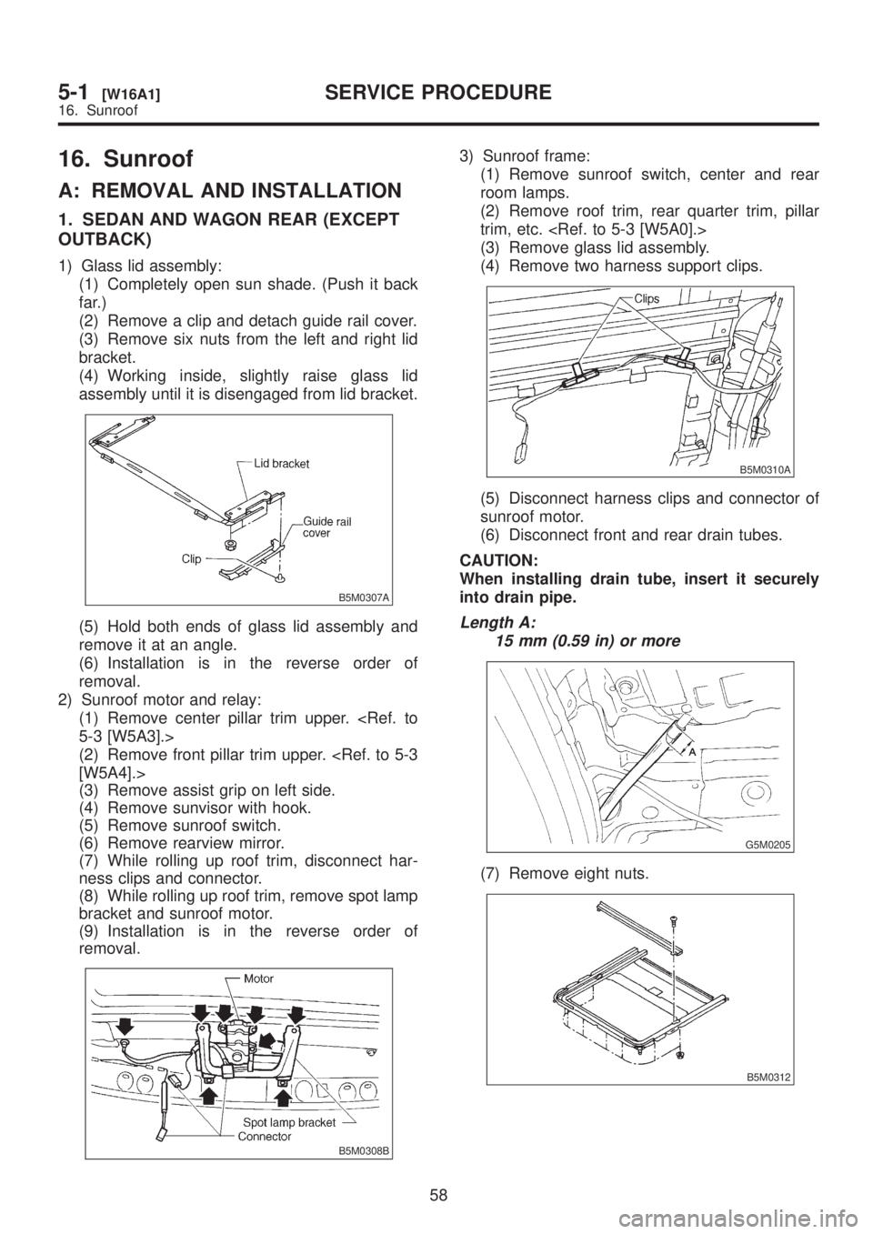
1) Glass lid assembly:
(1) Completely open sun shade. (Push it back
far.)
(2) Remove a clip and detach guide rail cover.
(3) Remove six nuts from the left and right lid
bracket.
(4) Working inside, slightly raise glass lid
assembly until it is disengaged from lid bracket.
B5M0307A
(5) Hold both ends of glass lid assembly and
remove it at an angle.
(6) Installation is in the reverse order of
removal.
2) Sunroof motor and relay:
(1) Remove center pillar trim upper.
(2) Remove front pillar trim upper.
(3) Remove assist grip on left side.
(4) Remove sunvisor with hook.
(5) Remove sunroof switch.
(6) Remove rearview mirror.
(7) While rolling up roof trim, disconnect har-
ness clips and connector.
(8) While rolling up roof trim, remove spot lamp
bracket and sunroof motor.
(9) Installation is in the reverse order of
removal.
B5M0308B
3) Sunroof frame:
(1) Remove sunroof switch, center and rear
room lamps.
(2) Remove roof trim, rear quarter trim, pillar
trim, etc.
(3) Remove glass lid assembly.
(4) Remove two harness support clips.
B5M0310A
(5) Disconnect harness clips and connector of
sunroof motor.
(6) Disconnect front and rear drain tubes.
CAUTION:
When installing drain tube, insert it securely
into drain pipe.
Length A:
15 mm (0.59 in) or more
G5M0205
(7) Remove eight nuts.
B5M0312
58
5-1[W16A1]SERVICE PROCEDURE
16. Sunroof
Page 1117 of 1456
![SUBARU LEGACY 1999 Service Repair Manual 10. GUSSET
1) Be sure window is all the way down.
2) Remove trim panel. <Ref. to 5-2 [W2A2].>
3) Remove door rearview mirror.
4) Remove sealing cover. <Ref. to 5-2 [W2A3].>
5) Remove bolts and nuts wh SUBARU LEGACY 1999 Service Repair Manual 10. GUSSET
1) Be sure window is all the way down.
2) Remove trim panel. <Ref. to 5-2 [W2A2].>
3) Remove door rearview mirror.
4) Remove sealing cover. <Ref. to 5-2 [W2A3].>
5) Remove bolts and nuts wh](/manual-img/17/57435/w960_57435-1116.png)
10. GUSSET
1) Be sure window is all the way down.
2) Remove trim panel.
3) Remove door rearview mirror.
4) Remove sealing cover.
5) Remove bolts and nuts which secure gusset
(A).
6) Lift out gusset (A).
B5M0070D
7) Installation is in the reverse order of removal.
11. REAR DOOR CATCHER
1) Open the rear door.
2) Using TORXTBIT (Tamper resistant type),
remove rear door catcher.
B5M0467A
3) Installation is in the reverse order of removal.
Tightening torque:
37
±10 N´m (3.8±1.0 kg-m, 27.5±7.2 ft-lb)
B: ADJUSTMENT
1. DOOR ASSEMBLY
1) Using ST, loosen bolts securing upper and
lower hinges to body, and adjust fore-and-aft and
vertical alignment of door.
ST 925610000 DOOR HINGE WRENCH
2) Loosen mounting screws approximately one
rotation. Adjust striker (A) position by lightly tap-
ping with hammer. (To adjust, utilize the shape of
striker nut plate support (B).)
CAUTION:
IUse cloth to prevent damaging body or other
parts.
IDo not directly tap striker plastic portion.
IDo not apply impact on spot-welded striker
nut plate.
Hinge tightening torque (body side):
29
±5 N´m (3.0±0.5 kg-m, 21.7±3.6 ft-lb)
Striker tightening torque:
14
±4 N´m (1.4±0.4 kg-m, 10.1±2.9 ft-lb)
B5M0071C
18
5-2[W2A10]SERVICE PROCEDURE
2. Door
Page 1138 of 1456
1. Door Glass
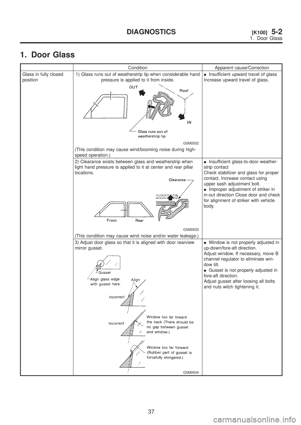
Condition Apparent cause/Correction
Glass in fully closed
position1) Glass runs out of weatherstrip lip when considerable hand
pressure is applied to it from inside.
G5M0502
IInsufficient upward travel of glass
Increase upward travel of glass.
(This condition may cause wind/booming noise during high-
speed operation.)
2) Clearance exists between glass and weatherstrip when
light hand pressure is applied to it at center and rear pillar
locations.
G5M0503
IInsufficient glass-to-door weather-
strip contact
Check stabilizer and glass for proper
contact. Increase contact using
upper sash adjustment bolt.
IImproper adjustment of striker in
in-out direction Close door and check
for alignment of striker with vehicle
body.
(This condition may cause wind noise and/or water leakage.)
3) Adjust door glass so that it is aligned with door rearview
mirror gusset.
G5M0504
IWindow is not properly adjusted in
up-down/fore-aft direction.
Adjust window. If necessary, move B
channel regulator to eliminate win-
dow tilt.
IGusset is not properly adjusted in
fore-aft direction.
Adjust gusset after loosing all bolts
and nuts witch tightening it.
37
[K100]5-2DIAGNOSTICS
1. Door Glass
Page 1265 of 1456
19. Remote Controlled
Rearview Mirror
A: REMOVAL AND INSTALLATION
1. REMOTE CONTROLLED REARVIEW
MIRROR SWITCH
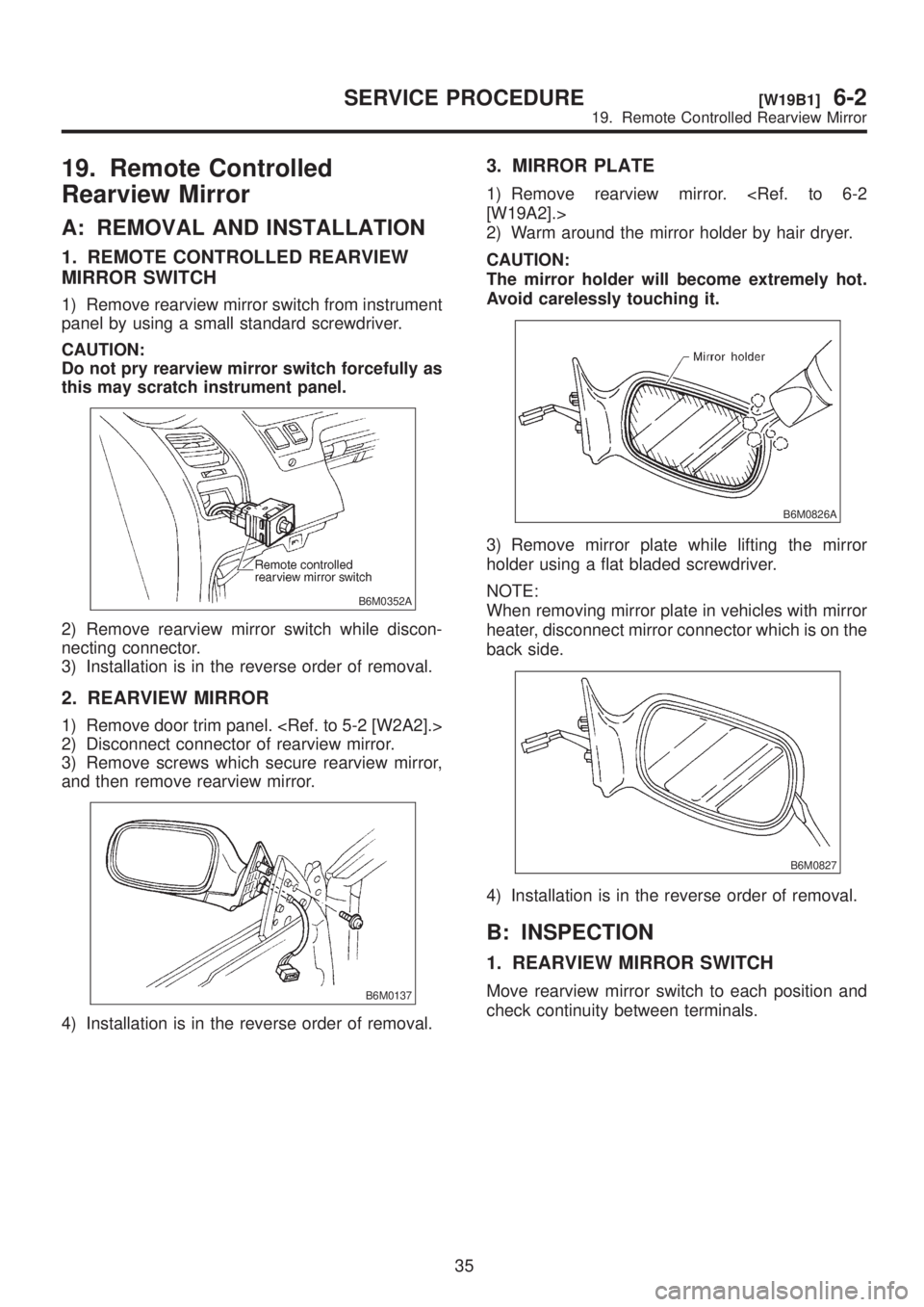
1) Remove rearview mirror switch from instrument
panel by using a small standard screwdriver.
CAUTION:
Do not pry rearview mirror switch forcefully as
this may scratch instrument panel.
B6M0352A
2) Remove rearview mirror switch while discon-
necting connector.
3) Installation is in the reverse order of removal.
2. REARVIEW MIRROR
1) Remove door trim panel.
2) Disconnect connector of rearview mirror.
3) Remove screws which secure rearview mirror,
and then remove rearview mirror.
B6M0137
4) Installation is in the reverse order of removal.
3. MIRROR PLATE
1) Remove rearview mirror.
2) Warm around the mirror holder by hair dryer.
CAUTION:
The mirror holder will become extremely hot.
Avoid carelessly touching it.
B6M0826A
3) Remove mirror plate while lifting the mirror
holder using a flat bladed screwdriver.
NOTE:
When removing mirror plate in vehicles with mirror
heater, disconnect mirror connector which is on the
back side.
B6M0827
4) Installation is in the reverse order of removal.
B: INSPECTION
1. REARVIEW MIRROR SWITCH
Move rearview mirror switch to each position and
check continuity between terminals.
35
[W19B1]6-2SERVICE PROCEDURE
19. Remote Controlled Rearview Mirror
Page 1266 of 1456
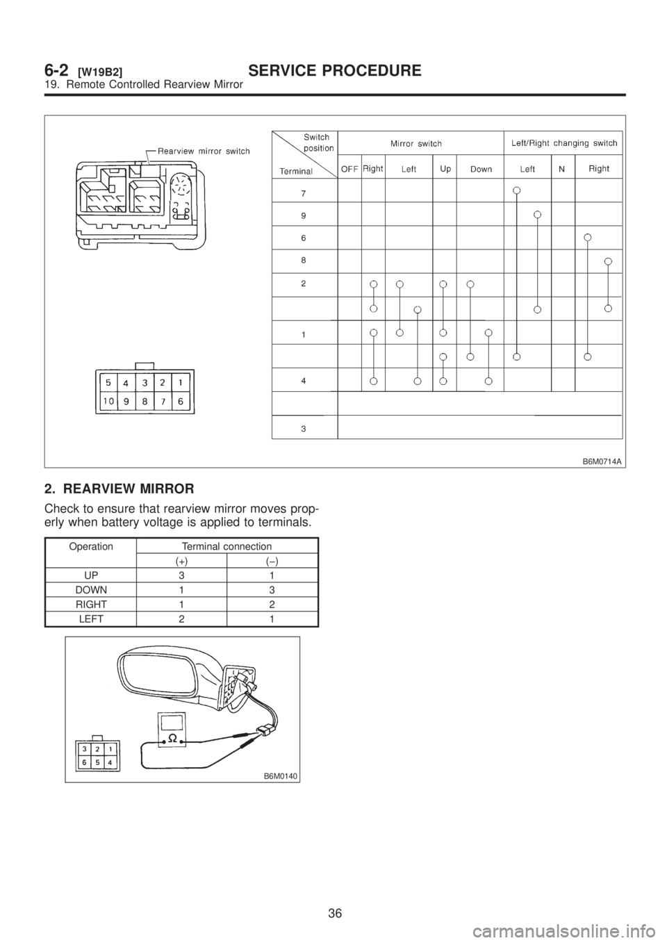
B6M0714A
2. REARVIEW MIRROR
Check to ensure that rearview mirror moves prop-
erly when battery voltage is applied to terminals.
Operation Terminal connection
(+) (þ)
UP 3 1
DOWN 1 3
RIGHT 1 2
LEFT 2 1
B6M0140
36
6-2[W19B2]SERVICE PROCEDURE
19. Remote Controlled Rearview Mirror
Page 1269 of 1456
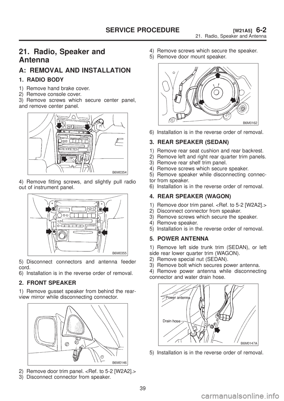
21. Radio, Speaker and
Antenna
A: REMOVAL AND INSTALLATION
1. RADIO BODY
1) Remove hand brake cover.
2) Remove console cover.
3) Remove screws which secure center panel,
and remove center panel.
B6M0354
4) Remove fitting screws, and slightly pull radio
out of instrument panel.
B6M0355
5) Disconnect connectors and antenna feeder
cord.
6) Installation is in the reverse order of removal.
2. FRONT SPEAKER
1) Remove gusset speaker from behind the rear-
view mirror while disconnecting connector.
B6M0146
2) Remove door trim panel.
3) Disconnect connector from speaker.4) Remove screws which secure the speaker.
5) Remove door mount speaker.
B6M0162
6) Installation is in the reverse order of removal.
3. REAR SPEAKER (SEDAN)
1) Remove rear seat cushion and rear backrest.
2) Remove left and right rear quarter trim panels.
3) Remove rear shelf trim panel.
4) Remove screws which secure speaker.
5) Remove speaker while disconnecting connec-
tor from speaker.
6) Installation is in the reverse order of removal.
4. REAR SPEAKER (WAGON)
1) Remove door trim panel.
2) Disconnect connector from speaker.
3) Remove screws which secure the speaker.
4) Remove speaker.
5) Installation is in the reverse order of removal.
5. POWER ANTENNA
1) Remove left side trunk trim (SEDAN), or left
side rear lower quarter trim (WAGON).
2) Remove special nut (SEDAN).
3) Remove bolt which secures power antenna.
4) Remove power antenna while disconnecting
connector and water drain hose.
B6M0147A
5) Installation is in the reverse order of removal.
39
[W21A5]6-2SERVICE PROCEDURE
21. Radio, Speaker and Antenna
Page 1296 of 1456
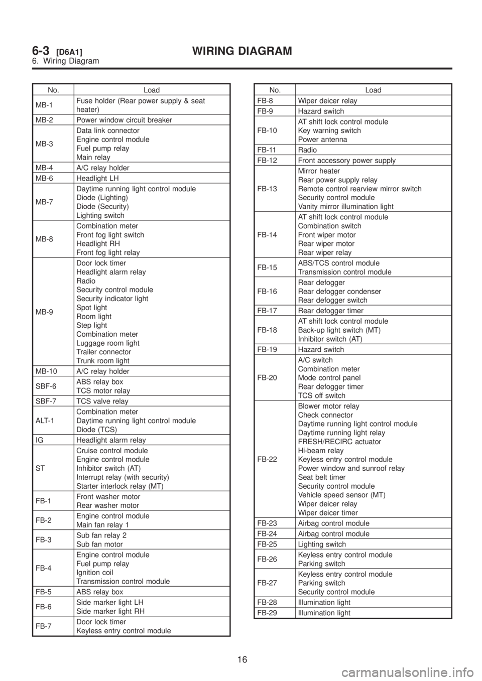
No. Load
MB-1Fuse holder (Rear power supply & seat
heater)
MB-2 Power window circuit breaker
MB-3Data link connector
Engine control module
Fuel pump relay
Main relay
MB-4 A/C relay holder
MB-6 Headlight LH
MB-7Daytime running light control module
Diode (Lighting)
Diode (Security)
Lighting switch
MB-8Combination meter
Front fog light switch
Headlight RH
Front fog light relay
MB-9Door lock timer
Headlight alarm relay
Radio
Security control module
Security indicator light
Spot light
Room light
Step light
Combination meter
Luggage room light
Trailer connector
Trunk room light
MB-10 A/C relay holder
SBF-6ABS relay box
TCS motor relay
SBF-7 TCS valve relay
ALT-1Combination meter
Daytime running light control module
Diode (TCS)
IG Headlight alarm relay
STCruise control module
Engine control module
Inhibitor switch (AT)
Interrupt relay (with security)
Starter interlock relay (MT)
FB-1Front washer motor
Rear washer motor
FB-2Engine control module
Main fan relay 1
FB-3Sub fan relay 2
Sub fan motor
FB-4Engine control module
Fuel pump relay
Ignition coil
Transmission control module
FB-5 ABS relay box
FB-6Side marker light LH
Side marker light RH
FB-7Door lock timer
Keyless entry control moduleNo. Load
FB-8 Wiper deicer relay
FB-9 Hazard switch
FB-10AT shift lock control module
Key warning switch
Power antenna
FB-11 Radio
FB-12 Front accessory power supply
FB-13Mirror heater
Rear power supply relay
Remote control rearview mirror switch
Security control module
Vanity mirror illumination light
FB-14AT shift lock control module
Combination switch
Front wiper motor
Rear wiper motor
Rear wiper relay
FB-15ABS/TCS control module
Transmission control module
FB-16Rear defogger
Rear defogger condenser
Rear defogger switch
FB-17 Rear defogger timer
FB-18AT shift lock control module
Back-up light switch (MT)
Inhibitor switch (AT)
FB-19 Hazard switch
FB-20A/C switch
Combination meter
Mode control panel
Rear defogger timer
TCS off switch
FB-22Blower motor relay
Check connector
Daytime running light control module
Daytime running light relay
FRESH/RECIRC actuator
Hi-beam relay
Keyless entry control module
Power window and sunroof relay
Seat belt timer
Security control module
Vehicle speed sensor (MT)
Wiper deicer relay
Wiper deicer timer
FB-23 Airbag control module
FB-24 Airbag control module
FB-25 Lighting switch
FB-26Keyless entry control module
Parking switch
FB-27Keyless entry control module
Parking switch
Security control module
FB-28 Illumination light
FB-29 Illumination light
16
6-3[D6A1]WIRING DIAGRAM
6. Wiring Diagram
Page 1300 of 1456
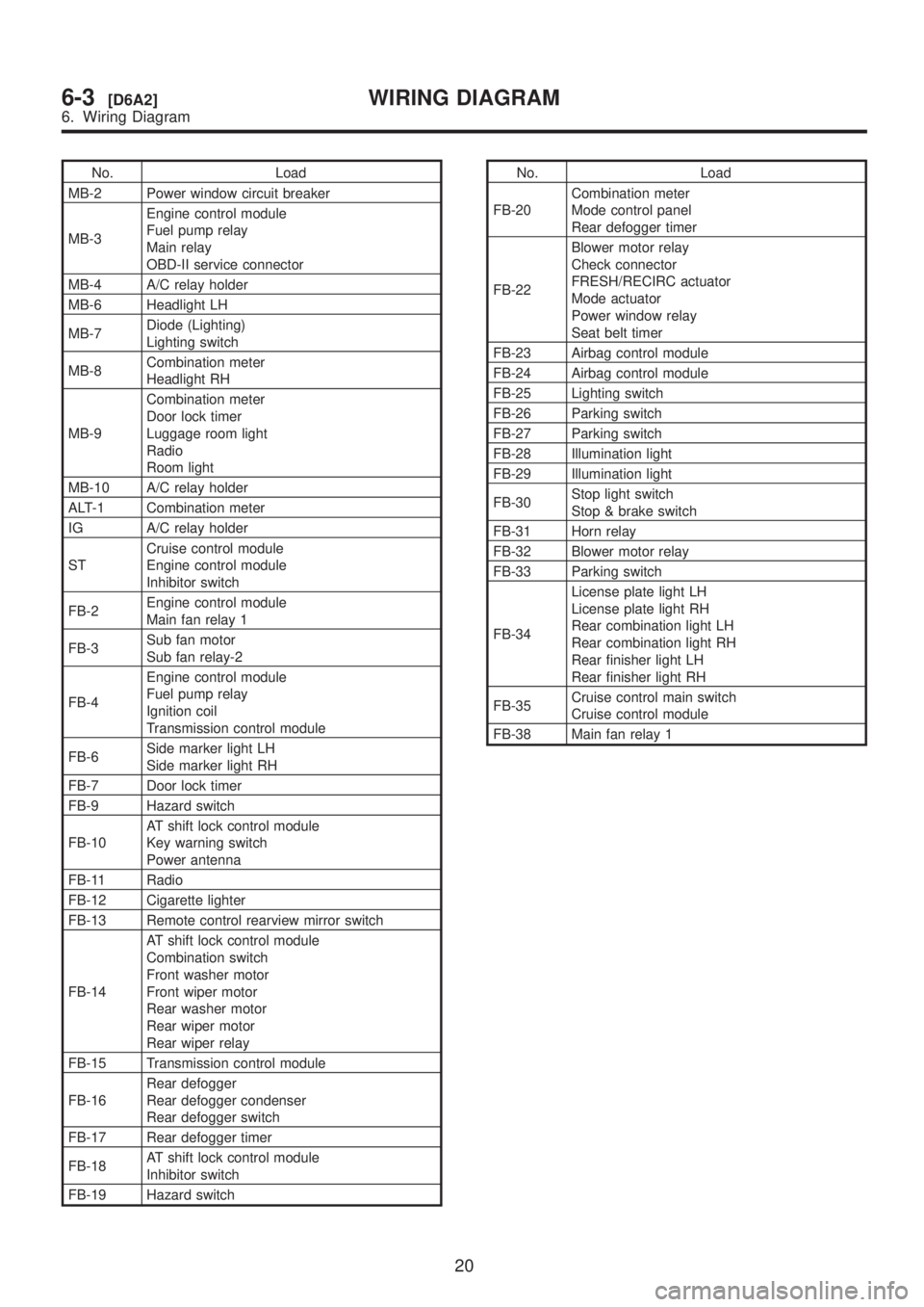
No. Load
MB-2 Power window circuit breaker
MB-3Engine control module
Fuel pump relay
Main relay
OBD-II service connector
MB-4 A/C relay holder
MB-6 Headlight LH
MB-7Diode (Lighting)
Lighting switch
MB-8Combination meter
Headlight RH
MB-9Combination meter
Door lock timer
Luggage room light
Radio
Room light
MB-10 A/C relay holder
ALT-1 Combination meter
IG A/C relay holder
STCruise control module
Engine control module
Inhibitor switch
FB-2Engine control module
Main fan relay 1
FB-3Sub fan motor
Sub fan relay-2
FB-4Engine control module
Fuel pump relay
Ignition coil
Transmission control module
FB-6Side marker light LH
Side marker light RH
FB-7 Door lock timer
FB-9 Hazard switch
FB-10AT shift lock control module
Key warning switch
Power antenna
FB-11 Radio
FB-12 Cigarette lighter
FB-13 Remote control rearview mirror switch
FB-14AT shift lock control module
Combination switch
Front washer motor
Front wiper motor
Rear washer motor
Rear wiper motor
Rear wiper relay
FB-15 Transmission control module
FB-16Rear defogger
Rear defogger condenser
Rear defogger switch
FB-17 Rear defogger timer
FB-18AT shift lock control module
Inhibitor switch
FB-19 Hazard switchNo. Load
FB-20Combination meter
Mode control panel
Rear defogger timer
FB-22Blower motor relay
Check connector
FRESH/RECIRC actuator
Mode actuator
Power window relay
Seat belt timer
FB-23 Airbag control module
FB-24 Airbag control module
FB-25 Lighting switch
FB-26 Parking switch
FB-27 Parking switch
FB-28 Illumination light
FB-29 Illumination light
FB-30Stop light switch
Stop & brake switch
FB-31 Horn relay
FB-32 Blower motor relay
FB-33 Parking switch
FB-34License plate light LH
License plate light RH
Rear combination light LH
Rear combination light RH
Rear finisher light LH
Rear finisher light RH
FB-35Cruise control main switch
Cruise control module
FB-38 Main fan relay 1
20
6-3[D6A2]WIRING DIAGRAM
6. Wiring Diagram