1999 SUBARU LEGACY washer fluid
[x] Cancel search: washer fluidPage 427 of 1456
6. Master Cylinder and
Reservoir Tank
A: REMOVAL
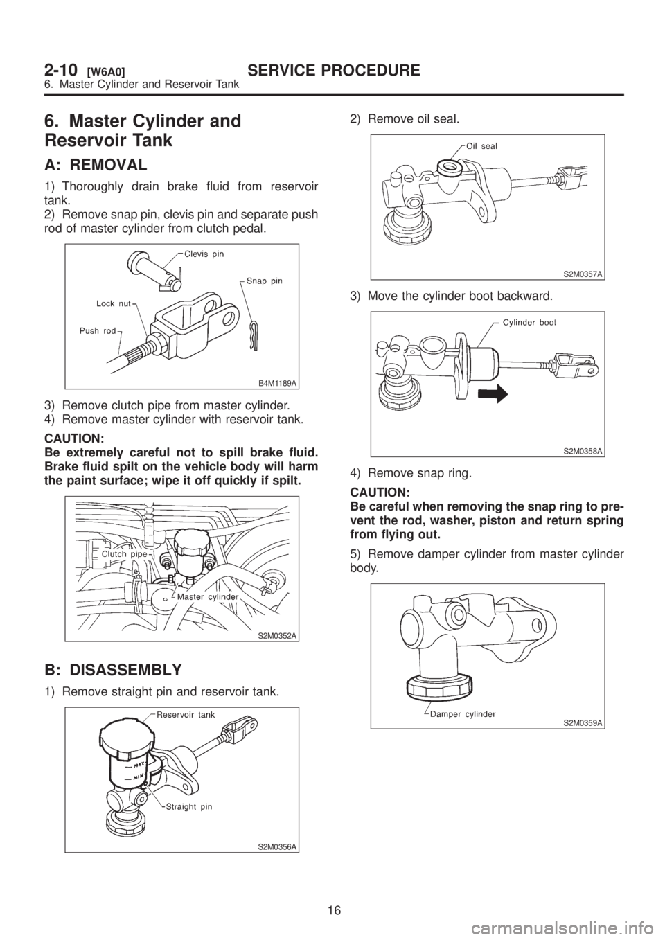
1) Thoroughly drain brake fluid from reservoir
tank.
2) Remove snap pin, clevis pin and separate push
rod of master cylinder from clutch pedal.
B4M1189A
3) Remove clutch pipe from master cylinder.
4) Remove master cylinder with reservoir tank.
CAUTION:
Be extremely careful not to spill brake fluid.
Brake fluid spilt on the vehicle body will harm
the paint surface; wipe it off quickly if spilt.
S2M0352A
B: DISASSEMBLY
1) Remove straight pin and reservoir tank.
S2M0356A
2) Remove oil seal.
S2M0357A
3) Move the cylinder boot backward.
S2M0358A
4) Remove snap ring.
CAUTION:
Be careful when removing the snap ring to pre-
vent the rod, washer, piston and return spring
from flying out.
5) Remove damper cylinder from master cylinder
body.
S2M0359A
16
2-10[W6A0]SERVICE PROCEDURE
6. Master Cylinder and Reservoir Tank
Page 428 of 1456

C: INSPECTION
If any damage, deformation, wear, swelling, rust or
other faults are found on the cylinder, piston, push
rod, fluid reservoir, return spring and gasket,
replace the faulty part.
S2M0353A
(A) Master cylinder body
(B) Return spring
(C) Piston
(D) Snap ring
(E) Rod assy
(F) Washer
(G) Damper cylinder
D: ASSEMBLY
CAUTION:
Apply a coat of grease to the contacting sur-
faces of the push rod and piston before instal-
lation.
1) To assemble the master cylinder reverse the
sequence of disassembly procedure.
2) Install damper cylinder washer. Install damper
cylinder and tighten to the specified torque.
Tightening torque:
T: 46.6
±7.4 N´m (4.75±0.75 kg-m, 34.4±5.4
ft-lb)
E: INSTALLATION
1) Install master cylinder to body, and install clutch
pipe to master cylinder.
CAUTION:
Check that pipe is routed properly.
Tightening torque:
T: 1 8
±3 N´m (1.8±0.3 kg-m, 13.0±2.2 ft-lb)
S2M0352B
2) Connect push rod of master cylinder to clutch
pedal, and install clevis pin and snap pin.
NOTE:
Apply grease to clevis pin.
B4M1189C
(A) Clevis pin
(B) Snap pin
(C) Push rod
3) After bleeding air from system, ensure that
clutch operates properly.
17
[W6E0]2-10SERVICE PROCEDURE
6. Master Cylinder and Reservoir Tank
Page 815 of 1456
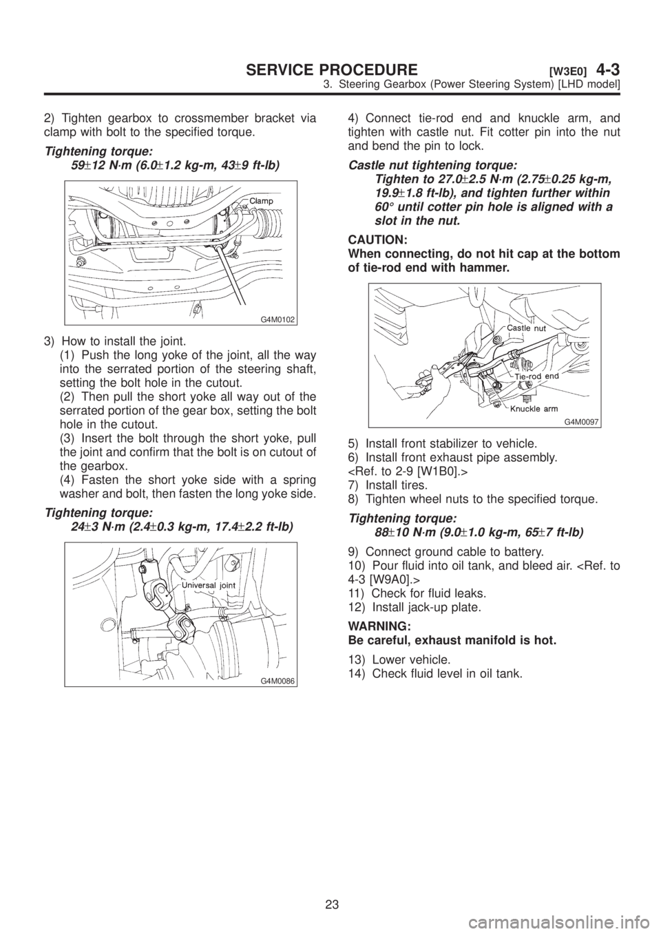
2) Tighten gearbox to crossmember bracket via
clamp with bolt to the specified torque.
Tightening torque:
59
±12 N´m (6.0±1.2 kg-m, 43±9 ft-lb)
G4M0102
3) How to install the joint.
(1) Push the long yoke of the joint, all the way
into the serrated portion of the steering shaft,
setting the bolt hole in the cutout.
(2) Then pull the short yoke all way out of the
serrated portion of the gear box, setting the bolt
hole in the cutout.
(3) Insert the bolt through the short yoke, pull
the joint and confirm that the bolt is on cutout of
the gearbox.
(4) Fasten the short yoke side with a spring
washer and bolt, then fasten the long yoke side.
Tightening torque:
24
±3 N´m (2.4±0.3 kg-m, 17.4±2.2 ft-lb)
G4M0086
4) Connect tie-rod end and knuckle arm, and
tighten with castle nut. Fit cotter pin into the nut
and bend the pin to lock.
Castle nut tightening torque:
Tighten to 27.0
±2.5 N´m (2.75±0.25 kg-m,
19.9
±1.8 ft-lb), and tighten further within
60É until cotter pin hole is aligned with a
slot in the nut.
CAUTION:
When connecting, do not hit cap at the bottom
of tie-rod end with hammer.
G4M0097
5) Install front stabilizer to vehicle.
6) Install front exhaust pipe assembly.
7) Install tires.
8) Tighten wheel nuts to the specified torque.
Tightening torque:
88
±10 N´m (9.0±1.0 kg-m, 65±7 ft-lb)
9) Connect ground cable to battery.
10) Pour fluid into oil tank, and bleed air.
11) Check for fluid leaks.
12) Install jack-up plate.
WARNING:
Be careful, exhaust manifold is hot.
13) Lower vehicle.
14) Check fluid level in oil tank.
23
[W3E0]4-3SERVICE PROCEDURE
3. Steering Gearbox (Power Steering System) [LHD model]
Page 830 of 1456
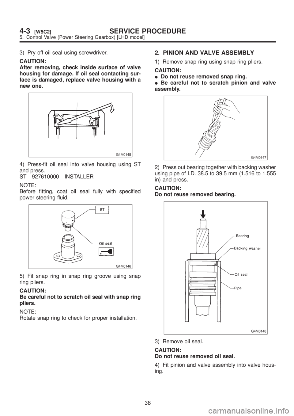
3) Pry off oil seal using screwdriver.
CAUTION:
After removing, check inside surface of valve
housing for damage. If oil seal contacting sur-
face is damaged, replace valve housing with a
new one.
G4M0145
4) Press-fit oil seal into valve housing using ST
and press.
ST 927610000 INSTALLER
NOTE:
Before fitting, coat oil seal fully with specified
power steering fluid.
G4M0146
5) Fit snap ring in snap ring groove using snap
ring pliers.
CAUTION:
Be careful not to scratch oil seal with snap ring
pliers.
NOTE:
Rotate snap ring to check for proper installation.
2. PINION AND VALVE ASSEMBLY
1) Remove snap ring using snap ring pliers.
CAUTION:
IDo not reuse removed snap ring.
IBe careful not to scratch pinion and valve
assembly.
G4M0147
2) Press out bearing together with backing washer
using pipe of I.D. 38.5 to 39.5 mm (1.516 to 1.555
in) and press.
CAUTION:
Do not reuse removed bearing.
G4M0148
3) Remove oil seal.
CAUTION:
Do not reuse removed oil seal.
4) Fit pinion and valve assembly into valve hous-
ing.
38
4-3[W5C2]SERVICE PROCEDURE
5. Control Valve (Power Steering Gearbox) [LHD model]
Page 831 of 1456
NOTE:
Apply specified power steering fluid to outer diam-
eter surface of input shaft and outer surface of
valve body seal ring, and pay special attention not
to damage seal when inserting pinion and valve
assembly.
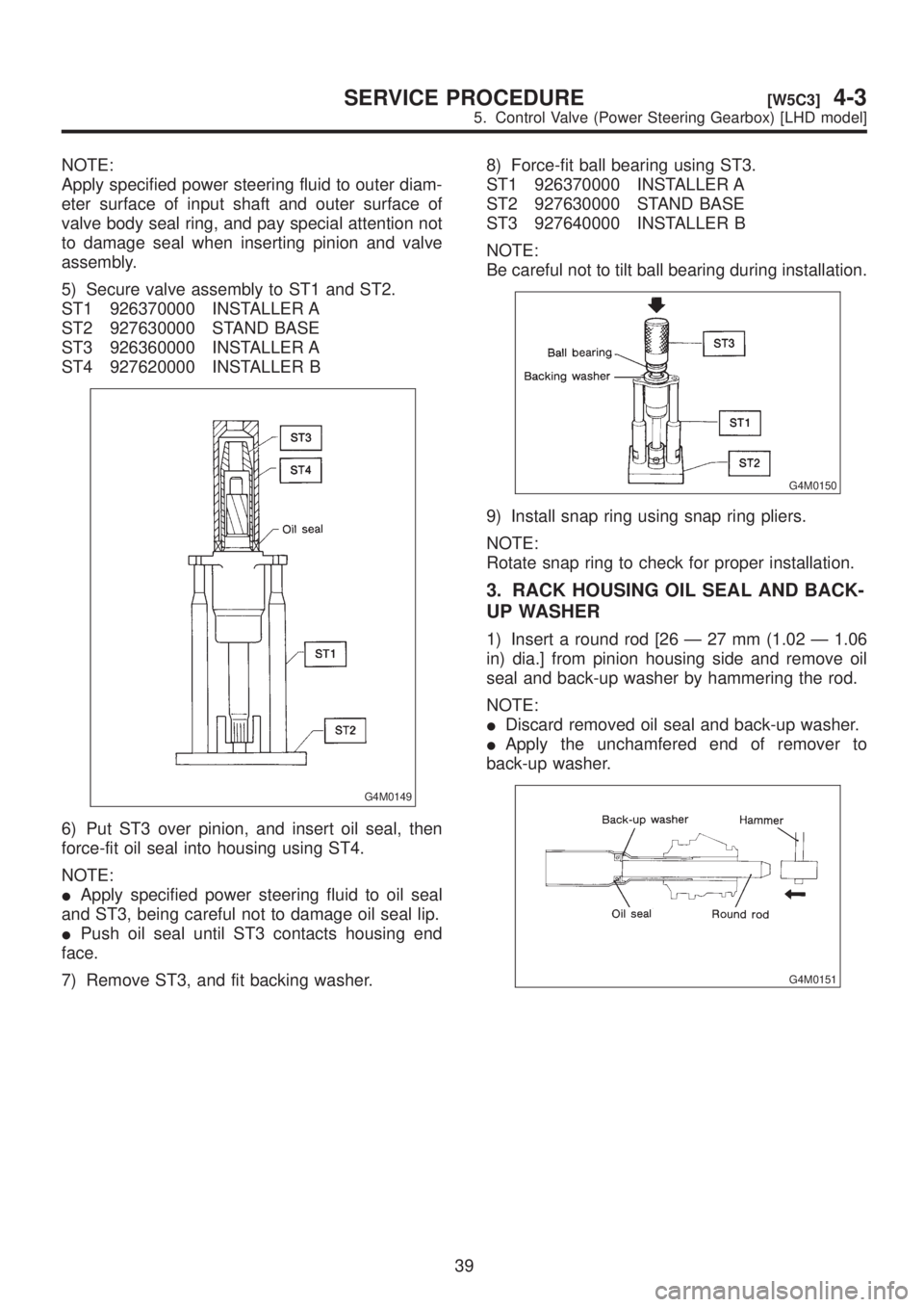
5) Secure valve assembly to ST1 and ST2.
ST1 926370000 INSTALLER A
ST2 927630000 STAND BASE
ST3 926360000 INSTALLER A
ST4 927620000 INSTALLER B
G4M0149
6) Put ST3 over pinion, and insert oil seal, then
force-fit oil seal into housing using ST4.
NOTE:
IApply specified power steering fluid to oil seal
and ST3, being careful not to damage oil seal lip.
IPush oil seal until ST3 contacts housing end
face.
7) Remove ST3, and fit backing washer.8) Force-fit ball bearing using ST3.
ST1 926370000 INSTALLER A
ST2 927630000 STAND BASE
ST3 927640000 INSTALLER B
NOTE:
Be careful not to tilt ball bearing during installation.
G4M0150
9) Install snap ring using snap ring pliers.
NOTE:
Rotate snap ring to check for proper installation.
3. RACK HOUSING OIL SEAL AND BACK-
UP WASHER
1) Insert a round rod [26 Ð 27 mm (1.02 Ð 1.06
in) dia.] from pinion housing side and remove oil
seal and back-up washer by hammering the rod.
NOTE:
IDiscard removed oil seal and back-up washer.
IApply the unchamfered end of remover to
back-up washer.
G4M0151
39
[W5C3]4-3SERVICE PROCEDURE
5. Control Valve (Power Steering Gearbox) [LHD model]
Page 832 of 1456
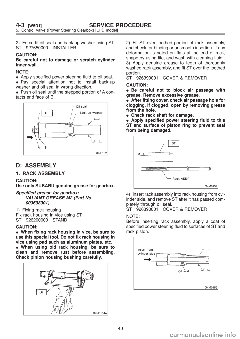
2) Force-fit oil seal and back-up washer using ST.
ST 927650000 INSTALLER
CAUTION:
Be careful not to damage or scratch cylinder
inner wall.
NOTE:
IApply specified power steering fluid to oil seal.
IPay special attention not to install back-up
washer and oil seal in wrong direction.
IPush oil seal until the stepped portion of A con-
tacts end face of B.
G4M0152
D: ASSEMBLY
1. RACK ASSEMBLY
CAUTION:
Use only SUBARU genuine grease for gearbox.
Specified grease for gearbox:
VALIANT GREASE M2 (Part No.
003608001)
1) Fixing rack housing
Fix rack housing in vice using ST.
ST 926200000 STAND
CAUTION:
IWhen fixing rack housing in vice, be sure to
use this special tool. Do not fix rack housing in
vice using pad such as aluminum plates, etc.
IWhen using old rack housing, be sure to
clean and remove rust before assembling.
Check pinion housing bushing carefully.
B4M0134A
2) Fit ST over toothed portion of rack assembly,
and check for binding or unsmooth insertion. If any
deformation is noted on flats at the end of rack,
shape by using file, and wash with cleaning fluid.
3) Apply genuine grease to teeth of thoroughly
washed rack assembly, and fit ST over the toothed
portion.
ST 926390001 COVER & REMOVER
CAUTION:
IBe careful not to block air passage with
grease. Remove excessive grease.
IAfter fitting cover, check air passage hole for
clogging. If clogged, open by removing grease
from the hole.
ICheck rack shaft for damage.
IApply specified power steering fluid to this
ST and surface of piston ring to prevent seal
from being damaged.
G4M0154
4) Insert rack assembly into rack housing from cyl-
inder side, and remove ST after it has passed com-
pletely through oil seal.
ST 926390001 COVER & REMOVER
NOTE:
Before inserting rack assembly, apply a coat of
specified power steering fluid to surfaces of ST and
rack piston.
G4M0155
40
4-3[W5D1]SERVICE PROCEDURE
5. Control Valve (Power Steering Gearbox) [LHD model]
Page 858 of 1456
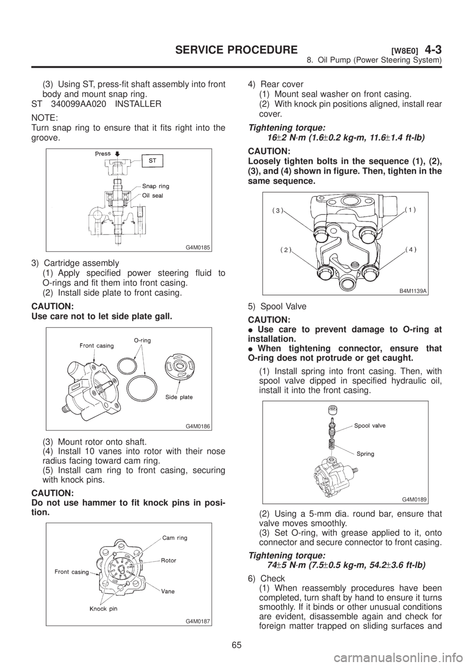
(3) Using ST, press-fit shaft assembly into front
body and mount snap ring.
ST 340099AA020 INSTALLER
NOTE:
Turn snap ring to ensure that it fits right into the
groove.
G4M0185
3) Cartridge assembly
(1) Apply specified power steering fluid to
O-rings and fit them into front casing.
(2) Install side plate to front casing.
CAUTION:
Use care not to let side plate gall.
G4M0186
(3) Mount rotor onto shaft.
(4) Install 10 vanes into rotor with their nose
radius facing toward cam ring.
(5) Install cam ring to front casing, securing
with knock pins.
CAUTION:
Do not use hammer to fit knock pins in posi-
tion.
G4M0187
4) Rear cover
(1) Mount seal washer on front casing.
(2) With knock pin positions aligned, install rear
cover.
Tightening torque:
16
±2 N´m (1.6±0.2 kg-m, 11.6±1.4 ft-lb)
CAUTION:
Loosely tighten bolts in the sequence (1), (2),
(3), and (4) shown in figure. Then, tighten in the
same sequence.
B4M1139A
5) Spool Valve
CAUTION:
IUse care to prevent damage to O-ring at
installation.
IWhen tightening connector, ensure that
O-ring does not protrude or get caught.
(1) Install spring into front casing. Then, with
spool valve dipped in specified hydraulic oil,
install it into the front casing.
G4M0189
(2) Using a 5-mm dia. round bar, ensure that
valve moves smoothly.
(3) Set O-ring, with grease applied to it, onto
connector and secure connector to front casing.
Tightening torque:
74
±5 N´m (7.5±0.5 kg-m, 54.2±3.6 ft-lb)
6) Check
(1) When reassembly procedures have been
completed, turn shaft by hand to ensure it turns
smoothly. If it binds or other unusual conditions
are evident, disassemble again and check for
foreign matter trapped on sliding surfaces and
65
[W8E0]4-3SERVICE PROCEDURE
8. Oil Pump (Power Steering System)
Page 1209 of 1456
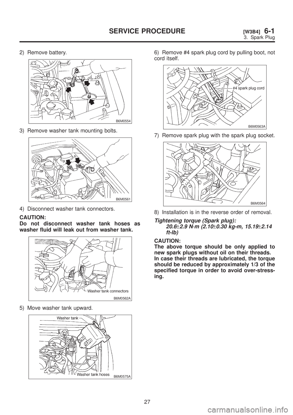
2) Remove battery.
B6M0554
3) Remove washer tank mounting bolts.
B6M0561
4) Disconnect washer tank connectors.
CAUTION:
Do not disconnect washer tank hoses as
washer fluid will leak out from washer tank.
B6M0562A
5) Move washer tank upward.
B6M0575A
6) Remove #4 spark plug cord by pulling boot, not
cord itself.
B6M0563A
7) Remove spark plug with the spark plug socket.
B6M0564
8) Installation is in the reverse order of removal.
Tightening torque (Spark plug):
20.6
±2.9 N´m (2.10±0.30 kg-m, 15.19±2.14
ft-lb)
CAUTION:
The above torque should be only applied to
new spark plugs without oil on their threads.
In case their threads are lubricated, the torque
should be reduced by approximately 1/3 of the
specified torque in order to avoid over-stress-
ing.
27
[W3B4]6-1SERVICE PROCEDURE
3. Spark Plug