1999 SUBARU LEGACY horn
[x] Cancel search: hornPage 805 of 1456

CAUTION:
Insert roll connector guide pin into guide hole
on lower end of surface of steering wheel to
prevent damage.
Draw out airbag system connector, horn con-
nector and cruise control connectors from
guide hole of steering wheel lower end. (with
airbag model)
8) Install airbag module to steering wheel. (with
airbag model)
WARNING:
Always refer to 5-5 Supplemental Restraint
System before performing the service opera-
tion.
Steering System) [LHD model]
A: REMOVAL
NOTE:
For disassembly and assembly of gearbox unit,
refer to section Control Valve (Power Steering
Gearbox) [LHD model].
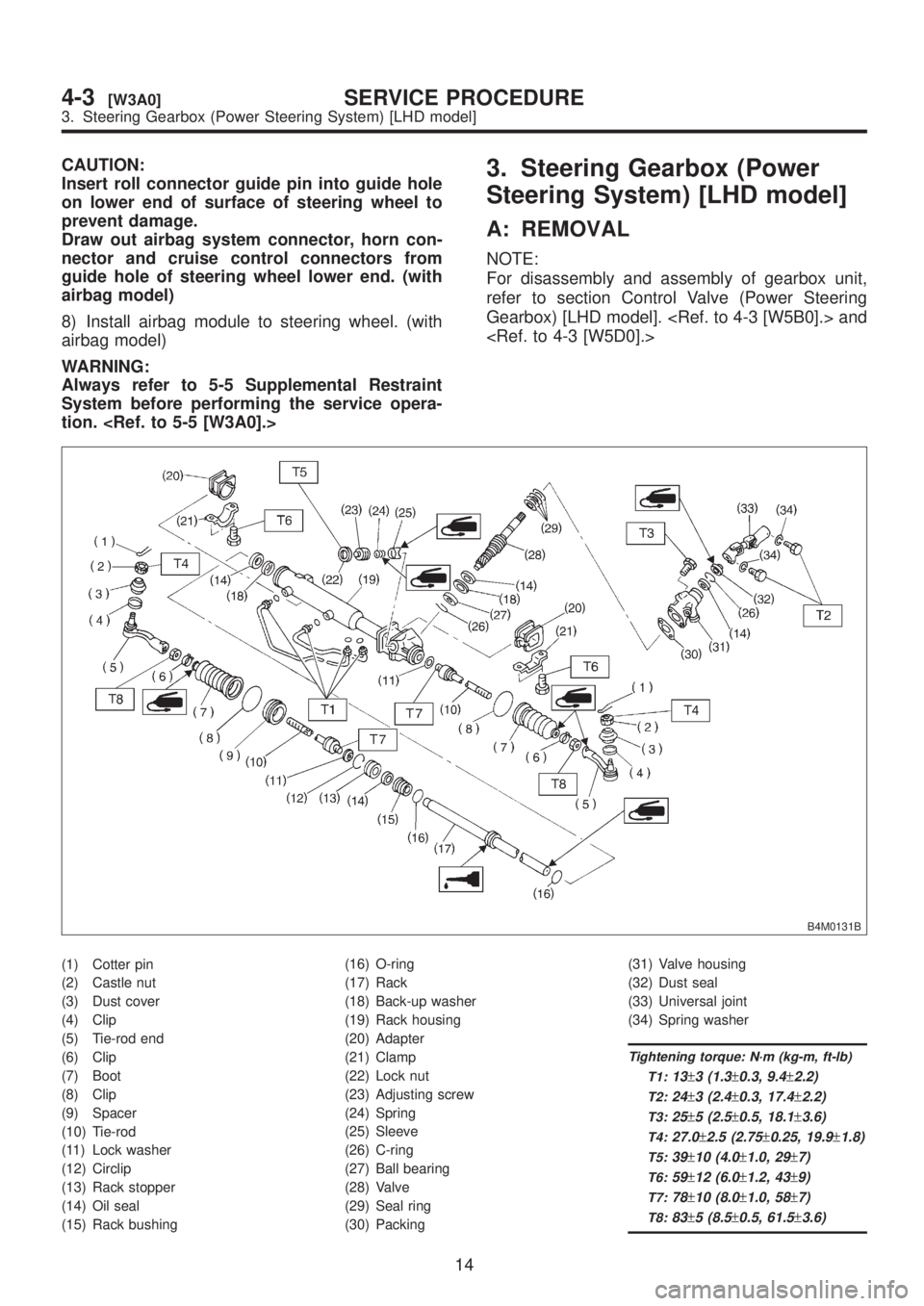
B4M0131B
(1) Cotter pin
(2) Castle nut
(3) Dust cover
(4) Clip
(5) Tie-rod end
(6) Clip
(7) Boot
(8) Clip
(9) Spacer
(10) Tie-rod
(11) Lock washer
(12) Circlip
(13) Rack stopper
(14) Oil seal
(15) Rack bushing(16) O-ring
(17) Rack
(18) Back-up washer
(19) Rack housing
(20) Adapter
(21) Clamp
(22) Lock nut
(23) Adjusting screw
(24) Spring
(25) Sleeve
(26) C-ring
(27) Ball bearing
(28) Valve
(29) Seal ring
(30) Packing(31) Valve housing
(32) Dust seal
(33) Universal joint
(34) Spring washer
Tightening torque: N´m (kg-m, ft-lb)
T1:
13±3 (1.3±0.3, 9.4±2.2)
T2:24±3 (2.4±0.3, 17.4±2.2)
T3:25±5 (2.5±0.5, 18.1±3.6)
T4:27.0±2.5 (2.75±0.25, 19.9±1.8)
T5:39±10 (4.0±1.0, 29±7)
T6:59±12 (6.0±1.2, 43±9)
T7:78±10 (8.0±1.0, 58±7)
T8:83±5 (8.5±0.5, 61.5±3.6)
14
4-3[W3A0]SERVICE PROCEDURE
3. Steering Gearbox (Power Steering System) [LHD model]
Page 806 of 1456
CAUTION:
Insert roll connector guide pin into guide hole
on lower end of surface of steering wheel to
prevent damage.
Draw out airbag system connector, horn con-
nector and cruise control connectors from
guide hole of steering wheel lower end. (with
airbag model)
8) Install airbag module to steering wheel. (with
airbag model)
WARNING:
Always refer to 5-5 Supplemental Restraint
System before performing the service opera-
tion.
Steering System) [LHD model]
A: REMOVAL
NOTE:
For disassembly and assembly of gearbox unit,
refer to section Control Valve (Power Steering
Gearbox) [LHD model].
B4M0131B
(1) Cotter pin
(2) Castle nut
(3) Dust cover
(4) Clip
(5) Tie-rod end
(6) Clip
(7) Boot
(8) Clip
(9) Spacer
(10) Tie-rod
(11) Lock washer
(12) Circlip
(13) Rack stopper
(14) Oil seal
(15) Rack bushing(16) O-ring
(17) Rack
(18) Back-up washer
(19) Rack housing
(20) Adapter
(21) Clamp
(22) Lock nut
(23) Adjusting screw
(24) Spring
(25) Sleeve
(26) C-ring
(27) Ball bearing
(28) Valve
(29) Seal ring
(30) Packing(31) Valve housing
(32) Dust seal
(33) Universal joint
(34) Spring washer
Tightening torque: N´m (kg-m, ft-lb)
T1:
13±3 (1.3±0.3, 9.4±2.2)
T2:24±3 (2.4±0.3, 17.4±2.2)
T3:25±5 (2.5±0.5, 18.1±3.6)
T4:27.0±2.5 (2.75±0.25, 19.9±1.8)
T5:39±10 (4.0±1.0, 29±7)
T6:59±12 (6.0±1.2, 43±9)
T7:78±10 (8.0±1.0, 58±7)
T8:83±5 (8.5±0.5, 61.5±3.6)
14
4-3[W3A0]SERVICE PROCEDURE
3. Steering Gearbox (Power Steering System) [LHD model]
Page 1226 of 1456
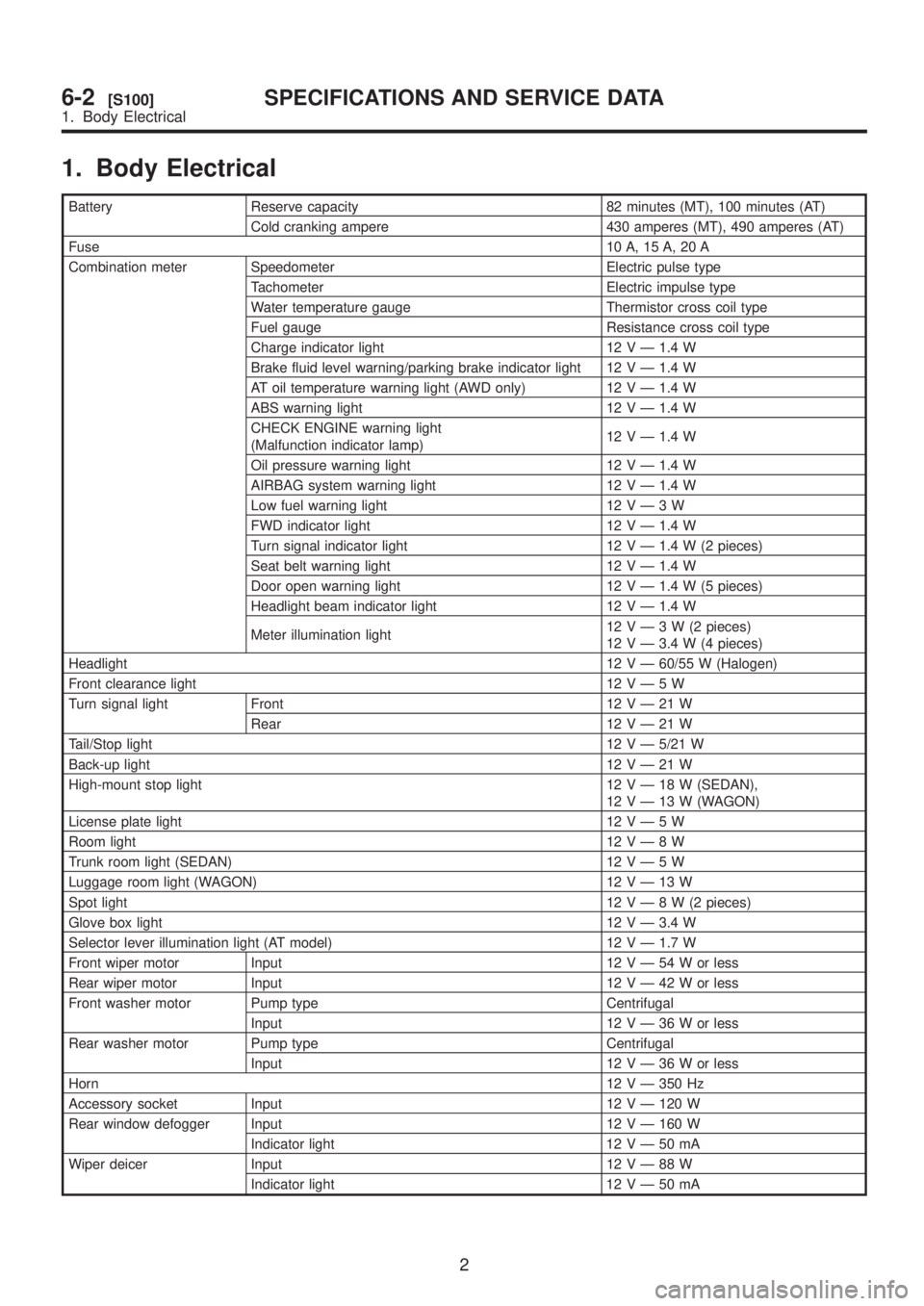
1. Body Electrical
Battery Reserve capacity 82 minutes (MT), 100 minutes (AT)
Cold cranking ampere 430 amperes (MT), 490 amperes (AT)
Fuse10 A, 15 A, 20 A
Combination meter Speedometer Electric pulse type
Tachometer Electric impulse type
Water temperature gauge Thermistor cross coil type
Fuel gauge Resistance cross coil type
Charge indicator light 12 V Ð 1.4 W
Brake fluid level warning/parking brake indicator light 12 V Ð 1.4 W
AT oil temperature warning light (AWD only) 12 V Ð 1.4 W
ABS warning light 12 V Ð 1.4 W
CHECK ENGINE warning light
(Malfunction indicator lamp)12 V Ð 1.4 W
Oil pressure warning light 12 V Ð 1.4 W
AIRBAG system warning light 12 V Ð 1.4 W
Low fuel warning light 12VÐ3W
FWD indicator light 12 V Ð 1.4 W
Turn signal indicator light 12 V Ð 1.4 W (2 pieces)
Seat belt warning light 12 V Ð 1.4 W
Door open warning light 12 V Ð 1.4 W (5 pieces)
Headlight beam indicator light 12 V Ð 1.4 W
Meter illumination light12VÐ3W(2pieces)
12 V Ð 3.4 W (4 pieces)
Headlight12 V Ð 60/55 W (Halogen)
Front clearance light 12VÐ5W
Turn signal light Front 12VÐ21W
Rear 12VÐ21W
Tail/Stop light12 V Ð 5/21 W
Back-up light12VÐ21W
High-mount stop light 12VÐ18W(SEDAN),
12VÐ13W(WAGON)
License plate light 12VÐ5W
Room light12VÐ8W
Trunk room light (SEDAN) 12VÐ5W
Luggage room light (WAGON) 12VÐ13W
Spot light12VÐ8W(2pieces)
Glove box light 12 V Ð 3.4 W
Selector lever illumination light (AT model) 12 V Ð 1.7 W
Front wiper motor Input 12VÐ54Worless
Rear wiper motor Input 12VÐ42Worless
Front washer motor Pump type Centrifugal
Input 12VÐ36Worless
Rear washer motor Pump type Centrifugal
Input 12VÐ36Worless
Horn12 V Ð 350 Hz
Accessory socket Input 12 V Ð 120 W
Rear window defogger Input 12 V Ð 160 W
Indicator light 12VÐ50mA
Wiper deicer Input 12VÐ88W
Indicator light 12VÐ50mA
2
6-2[S100]SPECIFICATIONS AND SERVICE DATA
1. Body Electrical
Page 1258 of 1456
16. Horn and Cigarette Lighter
A: REMOVAL AND INSTALLATION
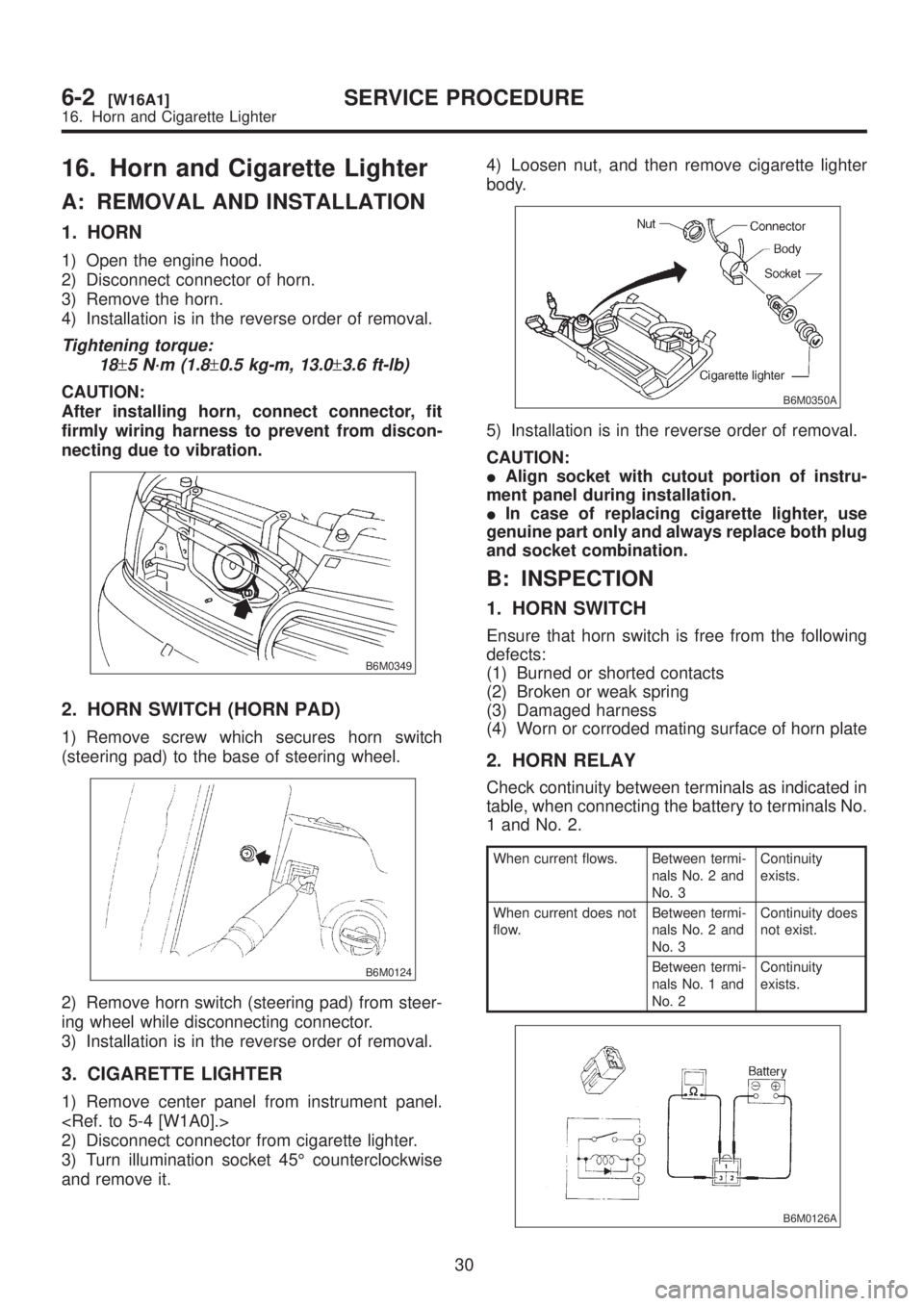
1. HORN
1) Open the engine hood.
2) Disconnect connector of horn.
3) Remove the horn.
4) Installation is in the reverse order of removal.
Tightening torque:
18
±5 N´m (1.8±0.5 kg-m, 13.0±3.6 ft-lb)
CAUTION:
After installing horn, connect connector, fit
firmly wiring harness to prevent from discon-
necting due to vibration.
B6M0349
2. HORN SWITCH (HORN PAD)
1) Remove screw which secures horn switch
(steering pad) to the base of steering wheel.
B6M0124
2) Remove horn switch (steering pad) from steer-
ing wheel while disconnecting connector.
3) Installation is in the reverse order of removal.
3. CIGARETTE LIGHTER
1) Remove center panel from instrument panel.
2) Disconnect connector from cigarette lighter.
3) Turn illumination socket 45É counterclockwise
and remove it.4) Loosen nut, and then remove cigarette lighter
body.
B6M0350A
5) Installation is in the reverse order of removal.
CAUTION:
IAlign socket with cutout portion of instru-
ment panel during installation.
IIn case of replacing cigarette lighter, use
genuine part only and always replace both plug
and socket combination.
B: INSPECTION
1. HORN SWITCH
Ensure that horn switch is free from the following
defects:
(1) Burned or shorted contacts
(2) Broken or weak spring
(3) Damaged harness
(4) Worn or corroded mating surface of horn plate
2. HORN RELAY
Check continuity between terminals as indicated in
table, when connecting the battery to terminals No.
1 and No. 2.
When current flows. Between termi-
nals No. 2 and
No. 3Continuity
exists.
When current does not
flow.Between termi-
nals No. 2 and
No. 3Continuity does
not exist.
Between termi-
nals No. 1 and
No. 2Continuity
exists.
B6M0126A
30
6-2[W16A1]SERVICE PROCEDURE
16. Horn and Cigarette Lighter
Page 1259 of 1456
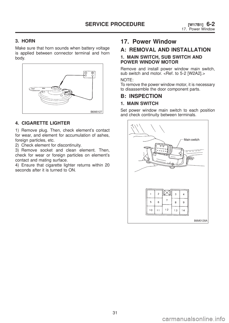
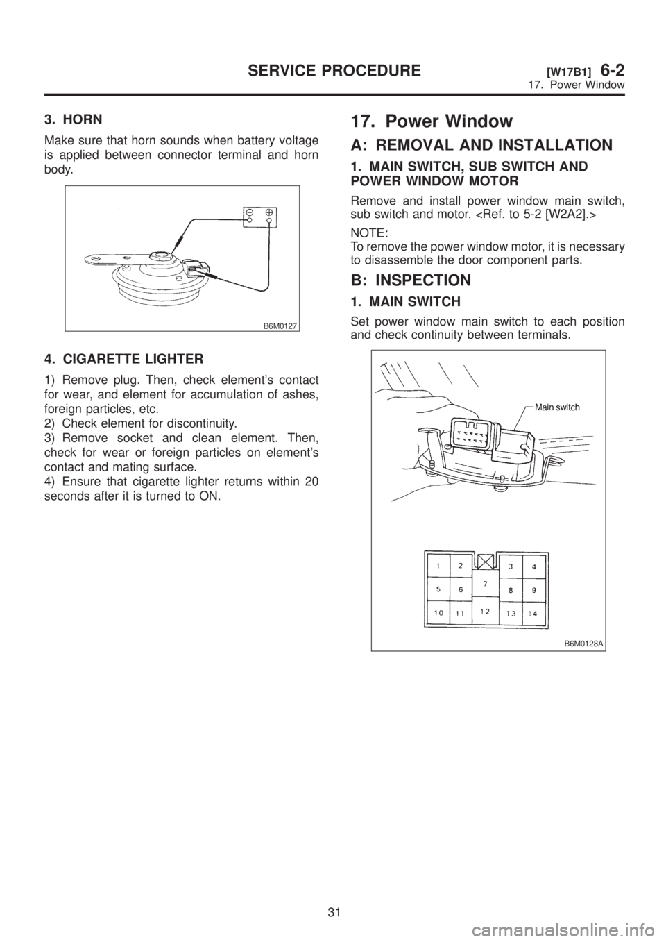
3. HORN
Make sure that horn sounds when battery voltage
is applied between connector terminal and horn
body.
B6M0127
4. CIGARETTE LIGHTER
1) Remove plug. Then, check element's contact
for wear, and element for accumulation of ashes,
foreign particles, etc.
2) Check element for discontinuity.
3) Remove socket and clean element. Then,
check for wear or foreign particles on element's
contact and mating surface.
4) Ensure that cigarette lighter returns within 20
seconds after it is turned to ON.
17. Power Window
A: REMOVAL AND INSTALLATION
1. MAIN SWITCH, SUB SWITCH AND
POWER WINDOW MOTOR
Remove and install power window main switch,
sub switch and motor.
NOTE:
To remove the power window motor, it is necessary
to disassemble the door component parts.
B: INSPECTION
1. MAIN SWITCH
Set power window main switch to each position
and check continuity between terminals.
B6M0128A
31
[W17B1]6-2SERVICE PROCEDURE
17. Power Window
Page 1260 of 1456
3. HORN
Make sure that horn sounds when battery voltage
is applied between connector terminal and horn
body.
B6M0127
4. CIGARETTE LIGHTER
1) Remove plug. Then, check element's contact
for wear, and element for accumulation of ashes,
foreign particles, etc.
2) Check element for discontinuity.
3) Remove socket and clean element. Then,
check for wear or foreign particles on element's
contact and mating surface.
4) Ensure that cigarette lighter returns within 20
seconds after it is turned to ON.
17. Power Window
A: REMOVAL AND INSTALLATION
1. MAIN SWITCH, SUB SWITCH AND
POWER WINDOW MOTOR
Remove and install power window main switch,
sub switch and motor.
NOTE:
To remove the power window motor, it is necessary
to disassemble the door component parts.
B: INSPECTION
1. MAIN SWITCH
Set power window main switch to each position
and check continuity between terminals.
B6M0128A
31
[W17B1]6-2SERVICE PROCEDURE
17. Power Window
Page 1272 of 1456
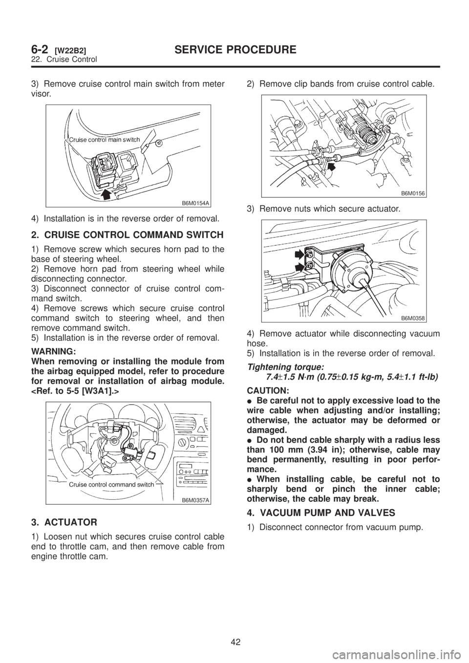
3) Remove cruise control main switch from meter
visor.
B6M0154A
4) Installation is in the reverse order of removal.
2. CRUISE CONTROL COMMAND SWITCH
1) Remove screw which secures horn pad to the
base of steering wheel.
2) Remove horn pad from steering wheel while
disconnecting connector.
3) Disconnect connector of cruise control com-
mand switch.
4) Remove screws which secure cruise control
command switch to steering wheel, and then
remove command switch.
5) Installation is in the reverse order of removal.
WARNING:
When removing or installing the module from
the airbag equipped model, refer to procedure
for removal or installation of airbag module.
B6M0357A
3. ACTUATOR
1) Loosen nut which secures cruise control cable
end to throttle cam, and then remove cable from
engine throttle cam.2) Remove clip bands from cruise control cable.
B6M0156
3) Remove nuts which secure actuator.
B6M0358
4) Remove actuator while disconnecting vacuum
hose.
5) Installation is in the reverse order of removal.
Tightening torque:
7.4
±1.5 N´m (0.75±0.15 kg-m, 5.4±1.1 ft-lb)
CAUTION:
IBe careful not to apply excessive load to the
wire cable when adjusting and/or installing;
otherwise, the actuator may be deformed or
damaged.
IDo not bend cable sharply with a radius less
than 100 mm (3.94 in); otherwise, cable may
bend permanently, resulting in poor perfor-
mance.
IWhen installing cable, be careful not to
sharply bend or pinch the inner cable;
otherwise, the cable may break.
4. VACUUM PUMP AND VALVES
1) Disconnect connector from vacuum pump.
42
6-2[W22B2]SERVICE PROCEDURE
22. Cruise Control
Page 1297 of 1456
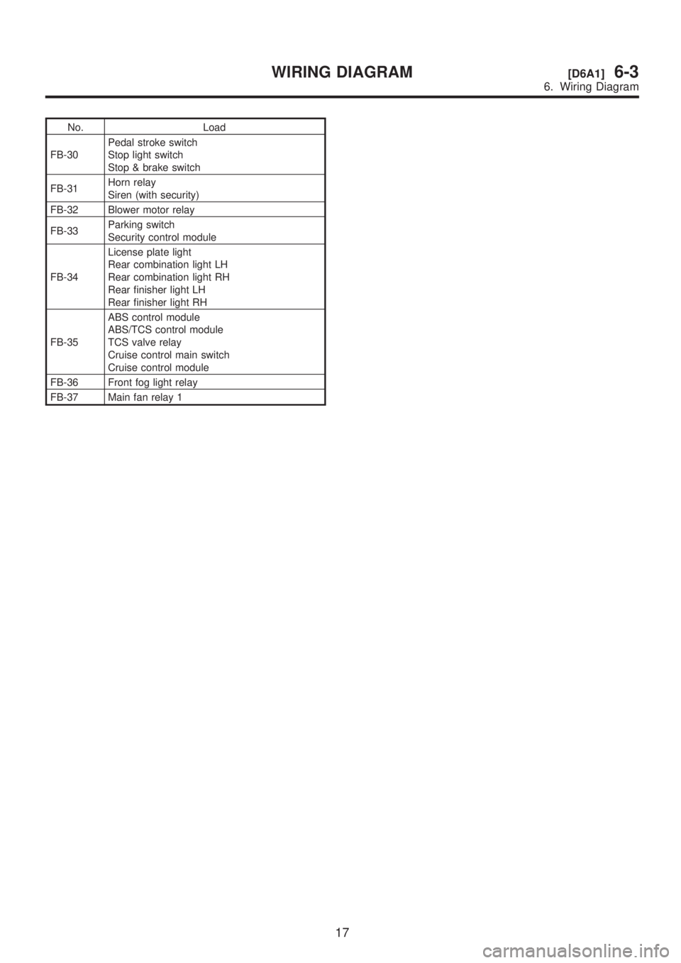
No. Load
FB-30Pedal stroke switch
Stop light switch
Stop & brake switch
FB-31Horn relay
Siren (with security)
FB-32 Blower motor relay
FB-33Parking switch
Security control module
FB-34License plate light
Rear combination light LH
Rear combination light RH
Rear finisher light LH
Rear finisher light RH
FB-35ABS control module
ABS/TCS control module
TCS valve relay
Cruise control main switch
Cruise control module
FB-36 Front fog light relay
FB-37 Main fan relay 1
17
[D6A1]6-3WIRING DIAGRAM
6. Wiring Diagram