1999 SUBARU LEGACY oil pressure
[x] Cancel search: oil pressurePage 40 of 1456

Diagnosis of engine condition by measurement of manifold vacuum
Vacuum gauge indication Possible engine condition
1. Needle is steady but lower than normal position. This ten-
dency becomes more evident as engine temperature rises.Leakage around intake manifold gasket or disconnection or
damaged vacuum hose
2. When engine speed is reduced slowly from higher speed,
needle stops temporarily when it is lowering or becomes
steady above normal position.Back pressure too high, or exhaust system clogged
3. Needle intermittently drops to position lower than normal
position.Leakage around cylinder
4. Needle drops suddenly and intermittently from normal posi-
tion.Sticky valves
5. When engine speed is gradually increased, needle begins
to vibrate rapidly at certain speed, and then vibration
increases as engine speed increases.Weak or broken valve springs
6. Needle vibrates above and below normal position in narrow
range.Defective ignition system or throttle chamber idle adjustment
6. Engine Oil Pressure
A: MEASUREMENT
1) Disconnect battery ground cable.
2) Remove generator from bracket.
(1) Disconnect connector and terminal from
generator.
G2M0088
(2) Remove V-belt cover
G2M0089
(3) Loosen lock bolt and slider bolt, and remove
V-belt for generator.
(4) Remove generator lock bolt.
(5) Remove bolt which install generator on
bracket.
G2M0090
3) Disconnect connector from oil pressure switch.
4) Remove oil pressure switch from engine cylin-
der block.
G2M0091
5) Connect oil pressure gauge hose to cylinder
block.
6) Connect battery ground cable.
7) Start the engine, and measure oil pressure.
6
2-2[W6A0]SERVICE PROCEDURE
6. Engine Oil Pressure
Page 41 of 1456

Diagnosis of engine condition by measurement of manifold vacuum
Vacuum gauge indication Possible engine condition
1. Needle is steady but lower than normal position. This ten-
dency becomes more evident as engine temperature rises.Leakage around intake manifold gasket or disconnection or
damaged vacuum hose
2. When engine speed is reduced slowly from higher speed,
needle stops temporarily when it is lowering or becomes
steady above normal position.Back pressure too high, or exhaust system clogged
3. Needle intermittently drops to position lower than normal
position.Leakage around cylinder
4. Needle drops suddenly and intermittently from normal posi-
tion.Sticky valves
5. When engine speed is gradually increased, needle begins
to vibrate rapidly at certain speed, and then vibration
increases as engine speed increases.Weak or broken valve springs
6. Needle vibrates above and below normal position in narrow
range.Defective ignition system or throttle chamber idle adjustment
6. Engine Oil Pressure
A: MEASUREMENT
1) Disconnect battery ground cable.
2) Remove generator from bracket.
(1) Disconnect connector and terminal from
generator.
G2M0088
(2) Remove V-belt cover
G2M0089
(3) Loosen lock bolt and slider bolt, and remove
V-belt for generator.
(4) Remove generator lock bolt.
(5) Remove bolt which install generator on
bracket.
G2M0090
3) Disconnect connector from oil pressure switch.
4) Remove oil pressure switch from engine cylin-
der block.
G2M0091
5) Connect oil pressure gauge hose to cylinder
block.
6) Connect battery ground cable.
7) Start the engine, and measure oil pressure.
6
2-2[W6A0]SERVICE PROCEDURE
6. Engine Oil Pressure
Page 42 of 1456
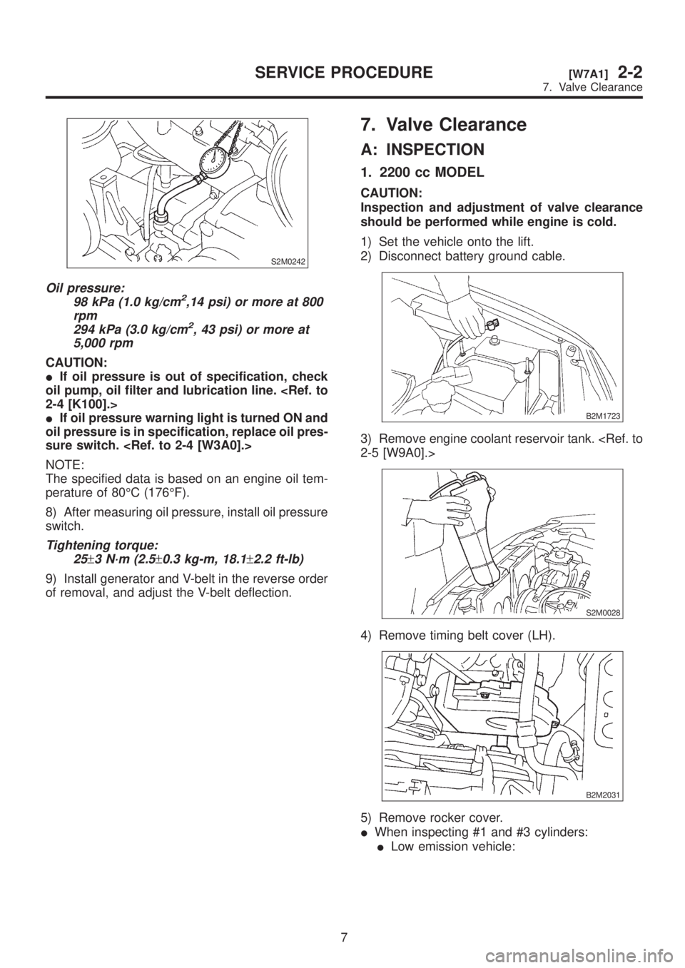
S2M0242
Oil pressure:
98 kPa (1.0 kg/cm2,14 psi) or more at 800
rpm
294 kPa (3.0 kg/cm
2, 43 psi) or more at
5,000 rpm
CAUTION:
IIf oil pressure is out of specification, check
oil pump, oil filter and lubrication line.
IIf oil pressure warning light is turned ON and
oil pressure is in specification, replace oil pres-
sure switch.
NOTE:
The specified data is based on an engine oil tem-
perature of 80ÉC (176ÉF).
8) After measuring oil pressure, install oil pressure
switch.
Tightening torque:
25
±3 N´m (2.5±0.3 kg-m, 18.1±2.2 ft-lb)
9) Install generator and V-belt in the reverse order
of removal, and adjust the V-belt deflection.
7. Valve Clearance
A: INSPECTION
1. 2200 cc MODEL
CAUTION:
Inspection and adjustment of valve clearance
should be performed while engine is cold.
1) Set the vehicle onto the lift.
2) Disconnect battery ground cable.
B2M1723
3) Remove engine coolant reservoir tank.
S2M0028
4) Remove timing belt cover (LH).
B2M2031
5) Remove rocker cover.
IWhen inspecting #1 and #3 cylinders:
ILow emission vehicle:
7
[W7A1]2-2SERVICE PROCEDURE
7. Valve Clearance
Page 43 of 1456
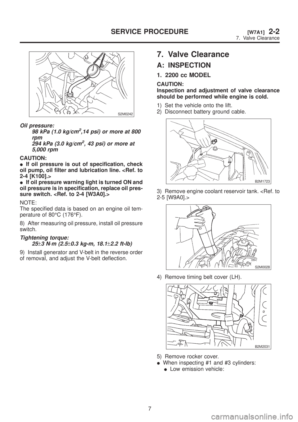
S2M0242
Oil pressure:
98 kPa (1.0 kg/cm2,14 psi) or more at 800
rpm
294 kPa (3.0 kg/cm
2, 43 psi) or more at
5,000 rpm
CAUTION:
IIf oil pressure is out of specification, check
oil pump, oil filter and lubrication line.
IIf oil pressure warning light is turned ON and
oil pressure is in specification, replace oil pres-
sure switch.
NOTE:
The specified data is based on an engine oil tem-
perature of 80ÉC (176ÉF).
8) After measuring oil pressure, install oil pressure
switch.
Tightening torque:
25
±3 N´m (2.5±0.3 kg-m, 18.1±2.2 ft-lb)
9) Install generator and V-belt in the reverse order
of removal, and adjust the V-belt deflection.
7. Valve Clearance
A: INSPECTION
1. 2200 cc MODEL
CAUTION:
Inspection and adjustment of valve clearance
should be performed while engine is cold.
1) Set the vehicle onto the lift.
2) Disconnect battery ground cable.
B2M1723
3) Remove engine coolant reservoir tank.
S2M0028
4) Remove timing belt cover (LH).
B2M2031
5) Remove rocker cover.
IWhen inspecting #1 and #3 cylinders:
ILow emission vehicle:
7
[W7A1]2-2SERVICE PROCEDURE
7. Valve Clearance
Page 55 of 1456
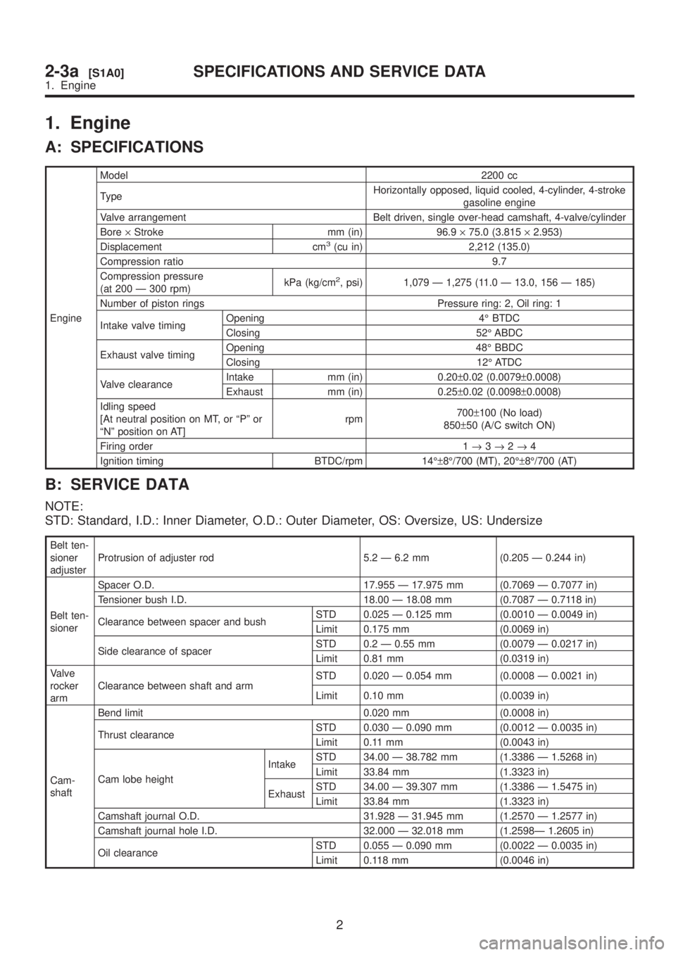
1. Engine
A: SPECIFICATIONS
EngineModel2200 cc
TypeHorizontally opposed, liquid cooled, 4-cylinder, 4-stroke
gasoline engine
Valve arrangement Belt driven, single over-head camshaft, 4-valve/cylinder
Bore´Stroke mm (in) 96.9´75.0 (3.815´2.953)
Displacement cm
3(cu in) 2,212 (135.0)
Compression ratio 9.7
Compression pressure
(at 200 Ð 300 rpm)kPa (kg/cm
2, psi) 1,079 Ð 1,275 (11.0 Ð 13.0, 156 Ð 185)
Number of piston rings Pressure ring: 2, Oil ring: 1
Intake valve timingOpening 4É BTDC
Closing 52É ABDC
Exhaust valve timingOpening 48É BBDC
Closing 12É ATDC
Valve clearanceIntake mm (in) 0.20±0.02 (0.0079±0.0008)
Exhaust mm (in) 0.25±0.02 (0.0098±0.0008)
Idling speed
[At neutral position on MT, or ªPº or
ªNº position on AT]rpm700±100 (No load)
850±50 (A/C switch ON)
Firing order 1®3®2®4
Ignition timing BTDC/rpm 14ɱ8É/700 (MT), 20ɱ8É/700 (AT)
B: SERVICE DATA
NOTE:
STD: Standard, I.D.: Inner Diameter, O.D.: Outer Diameter, OS: Oversize, US: Undersize
Belt ten-
sioner
adjusterProtrusion of adjuster rod 5.2 Ð 6.2 mm (0.205 Ð 0.244 in)
Belt ten-
sionerSpacer O.D. 17.955 Ð 17.975 mm (0.7069 Ð 0.7077 in)
Tensioner bush I.D. 18.00 Ð 18.08 mm (0.7087 Ð 0.7118 in)
Clearance between spacer and bushSTD 0.025 Ð 0.125 mm (0.0010 Ð 0.0049 in)
Limit 0.175 mm (0.0069 in)
Side clearance of spacerSTD 0.2 Ð 0.55 mm (0.0079 Ð 0.0217 in)
Limit 0.81 mm (0.0319 in)
Valve
rocker
armClearance between shaft and armSTD 0.020 Ð 0.054 mm (0.0008 Ð 0.0021 in)
Limit 0.10 mm (0.0039 in)
Cam-
shaftBend limit 0.020 mm (0.0008 in)
Thrust clearanceSTD 0.030 Ð 0.090 mm (0.0012 Ð 0.0035 in)
Limit 0.11 mm (0.0043 in)
Cam lobe heightIntakeSTD 34.00 Ð 38.782 mm (1.3386 Ð 1.5268 in)
Limit 33.84 mm (1.3323 in)
ExhaustSTD 34.00 Ð 39.307 mm (1.3386 Ð 1.5475 in)
Limit 33.84 mm (1.3323 in)
Camshaft journal O.D. 31.928 Ð 31.945 mm (1.2570 Ð 1.2577 in)
Camshaft journal hole I.D. 32.000 Ð 32.018 mm (1.2598Ð 1.2605 in)
Oil clearanceSTD 0.055 Ð 0.090 mm (0.0022 Ð 0.0035 in)
Limit 0.118 mm (0.0046 in)
2
2-3a[S1A0]SPECIFICATIONS AND SERVICE DATA
1. Engine
Page 62 of 1456
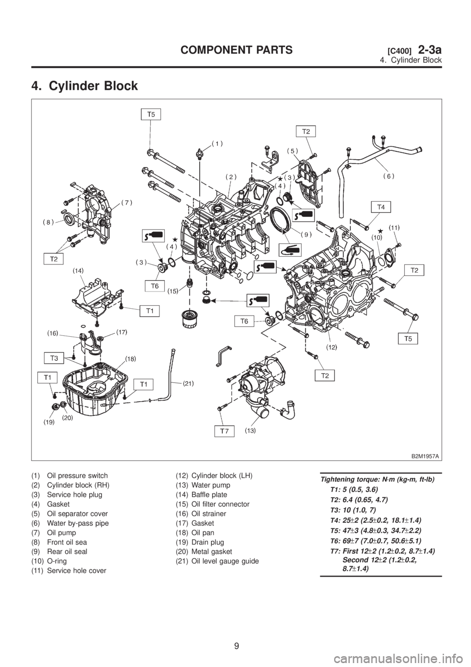
4. Cylinder Block
B2M1957A
(1) Oil pressure switch
(2) Cylinder block (RH)
(3) Service hole plug
(4) Gasket
(5) Oil separator cover
(6) Water by-pass pipe
(7) Oil pump
(8) Front oil sea
(9) Rear oil seal
(10) O-ring
(11) Service hole cover(12) Cylinder block (LH)
(13) Water pump
(14) Baffle plate
(15) Oil filter connector
(16) Oil strainer
(17) Gasket
(18) Oil pan
(19) Drain plug
(20) Metal gasket
(21) Oil level gauge guideTightening torque: N´m (kg-m, ft-lb)
T1:
5 (0.5, 3.6)
T2:6.4 (0.65, 4.7)
T3:10 (1.0, 7)
T4:25±2 (2.5±0.2, 18.1±1.4)
T5:47±3 (4.8±0.3, 34.7±2.2)
T6:69±7 (7.0±0.7, 50.6±5.1)
T7:First 12±2 (1.2±0.2, 8.7±1.4)
Second 12
±2 (1.2±0.2,
8.7
±1.4)
9
[C400]2-3aCOMPONENT PARTS
4. Cylinder Block
Page 71 of 1456
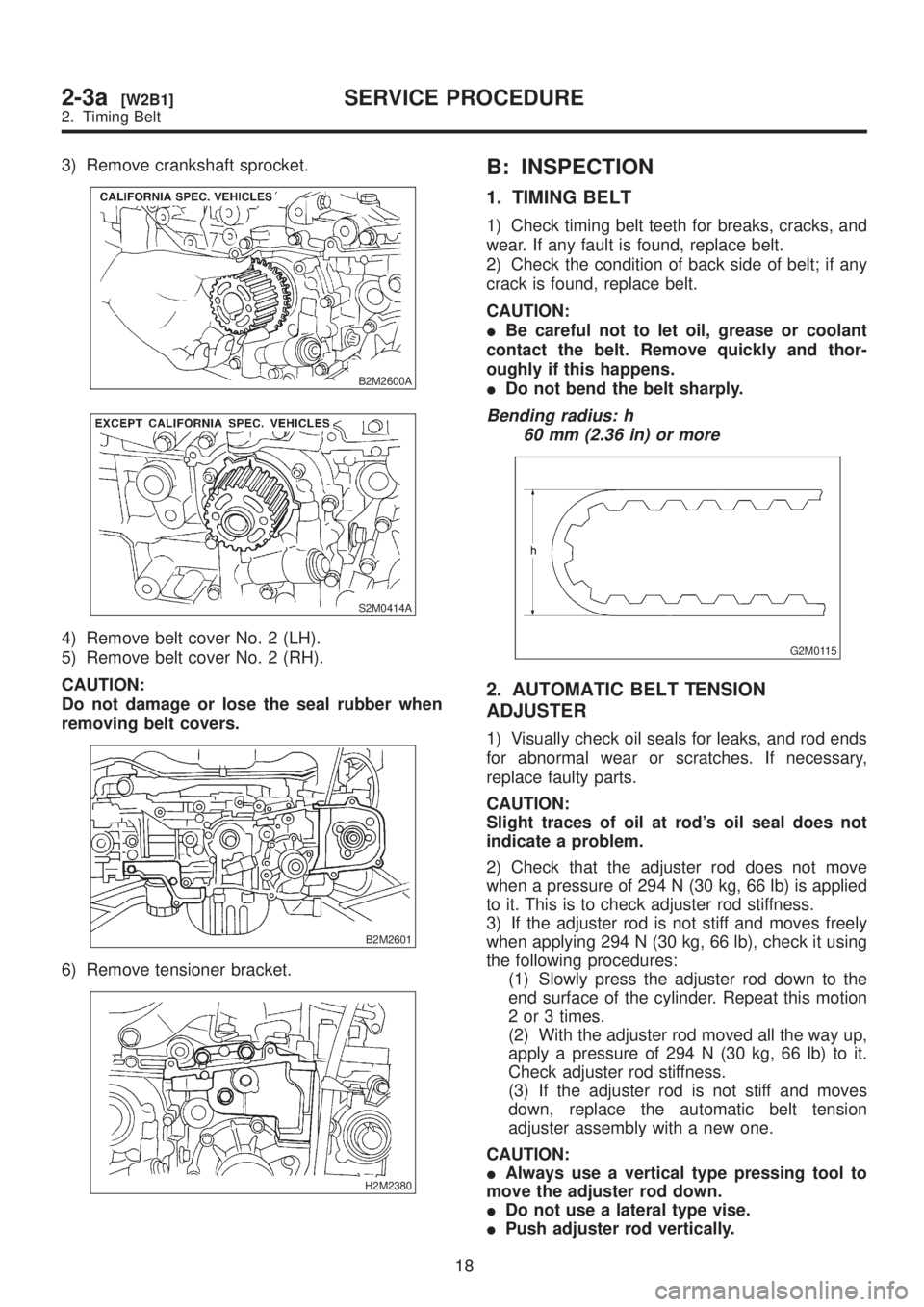
3) Remove crankshaft sprocket.
B2M2600A
S2M0414A
4) Remove belt cover No. 2 (LH).
5) Remove belt cover No. 2 (RH).
CAUTION:
Do not damage or lose the seal rubber when
removing belt covers.
B2M2601
6) Remove tensioner bracket.
H2M2380
B: INSPECTION
1. TIMING BELT
1) Check timing belt teeth for breaks, cracks, and
wear. If any fault is found, replace belt.
2) Check the condition of back side of belt; if any
crack is found, replace belt.
CAUTION:
IBe careful not to let oil, grease or coolant
contact the belt. Remove quickly and thor-
oughly if this happens.
IDo not bend the belt sharply.
Bending radius: h
60 mm (2.36 in) or more
G2M0115
2. AUTOMATIC BELT TENSION
ADJUSTER
1) Visually check oil seals for leaks, and rod ends
for abnormal wear or scratches. If necessary,
replace faulty parts.
CAUTION:
Slight traces of oil at rod's oil seal does not
indicate a problem.
2) Check that the adjuster rod does not move
when a pressure of 294 N (30 kg, 66 lb) is applied
to it. This is to check adjuster rod stiffness.
3) If the adjuster rod is not stiff and moves freely
when applying 294 N (30 kg, 66 lb), check it using
the following procedures:
(1) Slowly press the adjuster rod down to the
end surface of the cylinder. Repeat this motion
2 or 3 times.
(2) With the adjuster rod moved all the way up,
apply a pressure of 294 N (30 kg, 66 lb) to it.
Check adjuster rod stiffness.
(3) If the adjuster rod is not stiff and moves
down, replace the automatic belt tension
adjuster assembly with a new one.
CAUTION:
IAlways use a vertical type pressing tool to
move the adjuster rod down.
IDo not use a lateral type vise.
IPush adjuster rod vertically.
18
2-3a[W2B1]SERVICE PROCEDURE
2. Timing Belt
Page 94 of 1456
![SUBARU LEGACY 1999 Service Repair Manual 5. Cylinder Head
A: REMOVAL
1. RELATED PARTS
1) Release fuel pressure. <Ref. to 2-8 [W1B0].>
2) Drain engine coolant. <Ref. to 2-5 [W1A0].>
3) Remove V-belt(s).
4) Remove generator and bracket.
5) Rem SUBARU LEGACY 1999 Service Repair Manual 5. Cylinder Head
A: REMOVAL
1. RELATED PARTS
1) Release fuel pressure. <Ref. to 2-8 [W1B0].>
2) Drain engine coolant. <Ref. to 2-5 [W1A0].>
3) Remove V-belt(s).
4) Remove generator and bracket.
5) Rem](/manual-img/17/57435/w960_57435-93.png)
5. Cylinder Head
A: REMOVAL
1. RELATED PARTS
1) Release fuel pressure.
2) Drain engine coolant.
3) Remove V-belt(s).
4) Remove generator and bracket.
5) Remove A/C compressor and bracket. (With
A/C model)6) Disconnect spark plug cords.
7) Remove connector bracket attaching bolt.
8) Remove camshaft position sensor and cam-
shaft position sensor support.
9) Disconnect oil pressure switch connector.
10) Disconnect blow-by hose.
11) Remove intake manifold.
2. CYLINDER HEAD
B2M2627A
(1) Rocker cover
(2) Cylinder head bolt(3) Cylinder head
(4) Cylinder head gasket
1) Remove timing belt, camshaft sprocket and
related parts.
2) Remove oil level gauge guide attaching bolt
(left hand only) and oil level gauge guide.
3) Remove rocker cover.
40
2-3a[W5A1]SERVICE PROCEDURE
5. Cylinder Head