1999 SUBARU LEGACY instrument panel
[x] Cancel search: instrument panelPage 803 of 1456
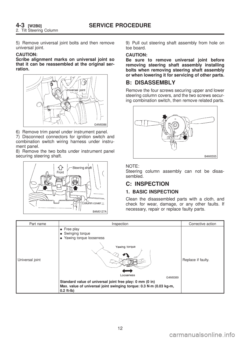
5) Remove universal joint bolts and then remove
universal joint.
CAUTION:
Scribe alignment marks on universal joint so
that it can be reassembled at the original ser-
ration.
G4M0086
6) Remove trim panel under instrument panel.
7) Disconnect connectors for ignition switch and
combination switch wiring harness under instru-
ment panel.
8) Remove the two bolts under instrument panel
securing steering shaft.
B4M0127A
9) Pull out steering shaft assembly from hole on
toe board.
CAUTION:
Be sure to remove universal joint before
removing steering shaft assembly installing
bolts when removing steering shaft assembly
or when lowering it for servicing of other parts.
B: DISASSEMBLY
Remove the four screws securing upper and lower
steering column covers, and the two screws secur-
ing combination switch, then remove related parts.
B4M0555
NOTE:
Steering column assembly can not be disas-
sembled.
C: INSPECTION
1. BASIC INSPECTION
Clean the disassembled parts with a cloth, and
check for wear, damage, or any other faults. If
necessary, repair or replace faulty parts.
Part name Inspection Corrective action
Universal jointIFree play
ISwinging torque
IYawing torque looseness
G4M0089
Standard value of universal joint free play: 0 mm (0 in)
Max. value of universal joint swinging torque: 0.3 N´m (0.03 kg-m,
0.2 ft-lb)Replace if faulty.
12
4-3[W2B0]SERVICE PROCEDURE
2. Tilt Steering Column
Page 804 of 1456
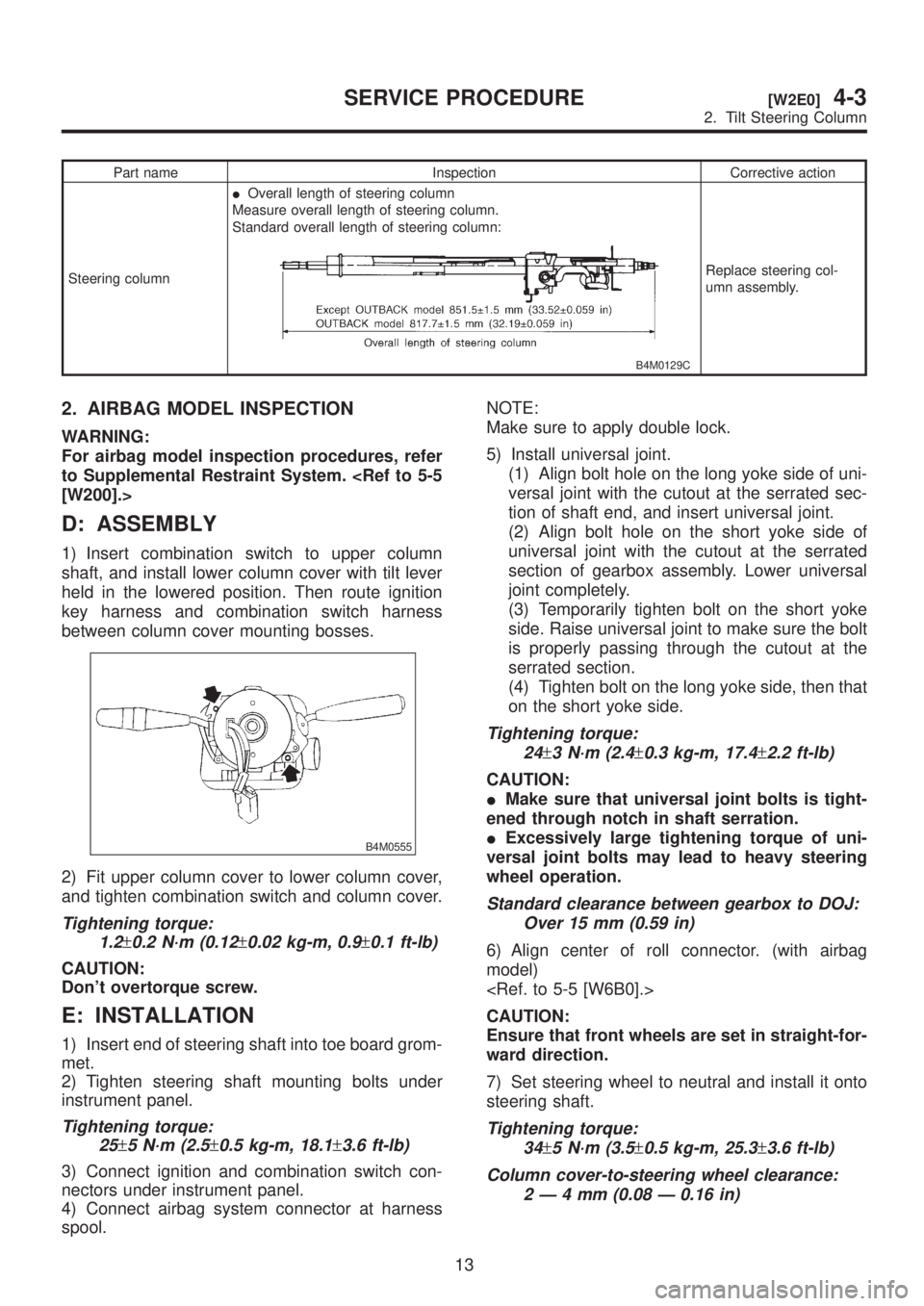
Part name Inspection Corrective action
Steering columnIOverall length of steering column
Measure overall length of steering column.
Standard overall length of steering column:
B4M0129C
Replace steering col-
umn assembly.
2. AIRBAG MODEL INSPECTION
WARNING:
For airbag model inspection procedures, refer
to Supplemental Restraint System.
[W200].>
D: ASSEMBLY
1) Insert combination switch to upper column
shaft, and install lower column cover with tilt lever
held in the lowered position. Then route ignition
key harness and combination switch harness
between column cover mounting bosses.
B4M0555
2) Fit upper column cover to lower column cover,
and tighten combination switch and column cover.
Tightening torque:
1.2
±0.2 N´m (0.12±0.02 kg-m, 0.9±0.1 ft-lb)
CAUTION:
Don't overtorque screw.
E: INSTALLATION
1) Insert end of steering shaft into toe board grom-
met.
2) Tighten steering shaft mounting bolts under
instrument panel.
Tightening torque:
25
±5 N´m (2.5±0.5 kg-m, 18.1±3.6 ft-lb)
3) Connect ignition and combination switch con-
nectors under instrument panel.
4) Connect airbag system connector at harness
spool.NOTE:
Make sure to apply double lock.
5) Install universal joint.
(1) Align bolt hole on the long yoke side of uni-
versal joint with the cutout at the serrated sec-
tion of shaft end, and insert universal joint.
(2) Align bolt hole on the short yoke side of
universal joint with the cutout at the serrated
section of gearbox assembly. Lower universal
joint completely.
(3) Temporarily tighten bolt on the short yoke
side. Raise universal joint to make sure the bolt
is properly passing through the cutout at the
serrated section.
(4) Tighten bolt on the long yoke side, then that
on the short yoke side.
Tightening torque:
24
±3 N´m (2.4±0.3 kg-m, 17.4±2.2 ft-lb)
CAUTION:
IMake sure that universal joint bolts is tight-
ened through notch in shaft serration.
IExcessively large tightening torque of uni-
versal joint bolts may lead to heavy steering
wheel operation.
Standard clearance between gearbox to DOJ:
Over 15 mm (0.59 in)
6) Align center of roll connector. (with airbag
model)
CAUTION:
Ensure that front wheels are set in straight-for-
ward direction.
7) Set steering wheel to neutral and install it onto
steering shaft.
Tightening torque:
34
±5 N´m (3.5±0.5 kg-m, 25.3±3.6 ft-lb)
Column cover-to-steering wheel clearance:
2Ð4mm(0.08 Ð 0.16 in)
13
[W2E0]4-3SERVICE PROCEDURE
2. Tilt Steering Column
Page 935 of 1456
4) Within 0.5 seconds after the ABS warning light
goes out, depress the brake pedal and hold it
immediately after ignition switch is turned to ON.
CAUTION:
Do not depress the clutch pedal.
NOTE:
IWhen the ignition switch is set to on, the brake
pedal must not be depressed.
IEngine must not operate.
5) After completion of ABS sequence control, turn
ignition switch OFF.
2. OPERATIONAL GUIDELINES OF THE
ABS SEQUENCE CONTROL WITH
SELECT MONITOR
NOTE:
IIn the event of any trouble, the sequence con-
trol may not be operative. In such a case, activate
the sequence control, referring to ªOPERATIONAL
GUIDELINES OF THE ABS SEQUENCE CON-
TROL WITH DIAGNOSIS CONNECTORº.
IWhen the diagnosis terminal is connected to the
diagnosis connector, the sequence control will not
operate.
1) Connect select monitor to data link connector
beside driver's seat instrument panel lower cover.
2) Turn ignition switch ON.
3) Turn select monitor switch ON.
4) Put select monitor to {ABS/TCS} mode.
5) When {Function check sequence} is selected,
`ABS sequence control' will start.
6) The message `Press Brake Pedal Firmly' is dis-
played as follows:
(1) When using the brake tester, depress brake
pedal with braking force of 981 N (100 kg, 221
lb).
(2) When using the pressure gauge, depress
brake pedal so as to make the pressure gauge
indicate 3,432 kPa (35 kg/cm
2, 498 psi).
CAUTION:
Do not depress the clutch pedal.
7) When the message ªPress YESº is displayed,
press YES key.
8) Operation points will be displayed on select
monitor.
3. CONDITIONS FOR COMPLETION OF
ABS SEQUENCE CONTROL
When the following conditions develop, the ABS
sequence control stops and ABS operation is
returned to the normal control mode.
1) When the speed of at least one wheel reaches
10 km/h (6 MPH).
2) When terminal No. 3 or No. 6 are separated
from diagnosis terminals. (When select monitor is
not used.)
3) When the brake pedal is released during
sequence control and the braking lamp switch is
set to off.
4) When brake pedal is depressed after ignition
key is turned to ON, and before ABS warning light
goes out. (When select monitor is not used.)
5) When brake pedal is not depressed after igni-
tion key is turned to ON, and within 0.5 seconds
after ABS warning light goes out. (When select
monitor is not used.)
6) After completion of the sequence control.
7) When malfunction is detected. (When select
monitor is used.)
58
4-4[W15D2]SERVICE PROCEDURE
15. ABS Control Module and Hydraulic Control Unit (ABSCM&H/U)
Page 953 of 1456
B: REMOVAL
1. ACCELERATOR PEDAL
1) Disconnect ground cable from battery.
2) Disconnect accelerator cable from throttle body.
CAUTION:
Be careful not to kink accelerator cable.
3) Remove instrument panel lower cover from
instrument panel, and connector.
4) Disconnect accelerator cable from accelerator
pedal lever.
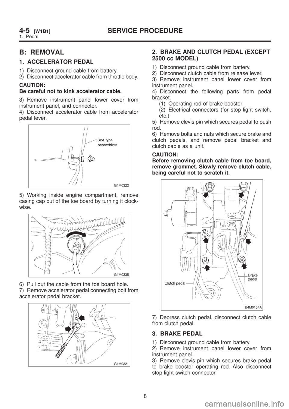
G4M0322
5) Working inside engine compartment, remove
casing cap out of the toe board by turning it clock-
wise.
G4M0335
6) Pull out the cable from the toe board hole.
7) Remove accelerator pedal connecting bolt from
accelerator pedal bracket.
G4M0321
2. BRAKE AND CLUTCH PEDAL (EXCEPT
2500 cc MODEL)
1) Disconnect ground cable from battery.
2) Disconnect clutch cable from release lever.
3) Remove instrument panel lower cover from
instrument panel.
4) Disconnect the following parts from pedal
bracket.
(1) Operating rod of brake booster
(2) Electrical connectors (for stop light switch,
etc.)
5) Remove clevis pin which secures pedal to push
rod.
6) Remove bolts and nuts which secure brake and
clutch pedals, and remove pedal bracket and
clutch cable as a unit.
CAUTION:
Before removing clutch cable from toe board,
remove grommet. Slowly remove clutch cable,
being careful not to scratch it.
B4M0154A
7) Depress clutch pedal, disconnect clutch cable
from clutch pedal.
3. BRAKE PEDAL
1) Disconnect ground cable from battery.
2) Remove instrument panel lower cover from
instrument panel.
3) Remove clevis pin which secures brake pedal
to brake booster operating rod. Also disconnect
stop light switch connector.
8
4-5[W1B1]SERVICE PROCEDURE
1. Pedal
Page 954 of 1456

4) Remove two bolts and four nuts which secure
brake pedal to pedal.
G4M0324
4. BRAKE AND CLUTCH PEDAL (2500 cc
MODEL)
1) Remove steering bolts.
2) Raise vehicle on hoist and remove the two bolts
which secure steering unit to underside of body.
3) Lower vehicle to floor.
4) Remove instrument panel lower cover from
instrument panel.
5) Disconnect the following parts from pedal
bracket.
IOperating rod of brake booster
IElectrical connectors (for stop light switch, etc.)
6) Remove clevis pin which secures lever to push
rod.
7) Remove nut which secures clutch master cylin-
der.
8) Remove steering assembly.
9) Remove bolts and nuts which secure brake and
clutch pedals, and remove pedal assembly.
C: INSPECTION
1. BRAKE AND CLUTCH PEDALS
Move brake and clutch pedal pads in the lateral
direction with a force of approximately 10 N (1 kg,
2 lb) to ensure pedal deflection is in specified
range.
Deflection of brake and clutch pedal:
Service limit
5.0 mm (0.197 in) or less
CAUTION:
If excessive deflection is noted, replace bush-
ings with new ones.
S4M0135A
G4M0326
9
[W1C1]4-5SERVICE PROCEDURE
1. Pedal
Page 967 of 1456
1. Precaution
A: SUPPLEMENTAL RESTRAINT
SYSTEM ªAIRBAGº
CAUTION:
IAll Airbag system wiring harness and con-
nectors are colored yellow. Do not use electri-
cal test equipment on these circuit.
IBe careful not to damage Airbag system wir-
ing harness when servicing the instrument
panel, heater unit, blower motor and control
unit.
Airbag system wiring harness is routed near the
instrument panel, heater unit, blower motor and
control unit.
2. Heater Unit
A: REMOVAL AND INSTALLATION
1) Disconnect GND cable from battery.
2) Remove heater hoses (inlet, outlet) in engine
compartment.
NOTE:
Drain as much coolant from heater unit as
possible, and plug disconnected hose with cloth.
3) Remove instrument panel.
4) Remove steering support beam.
5) Remove evaporator. (With A/C model)
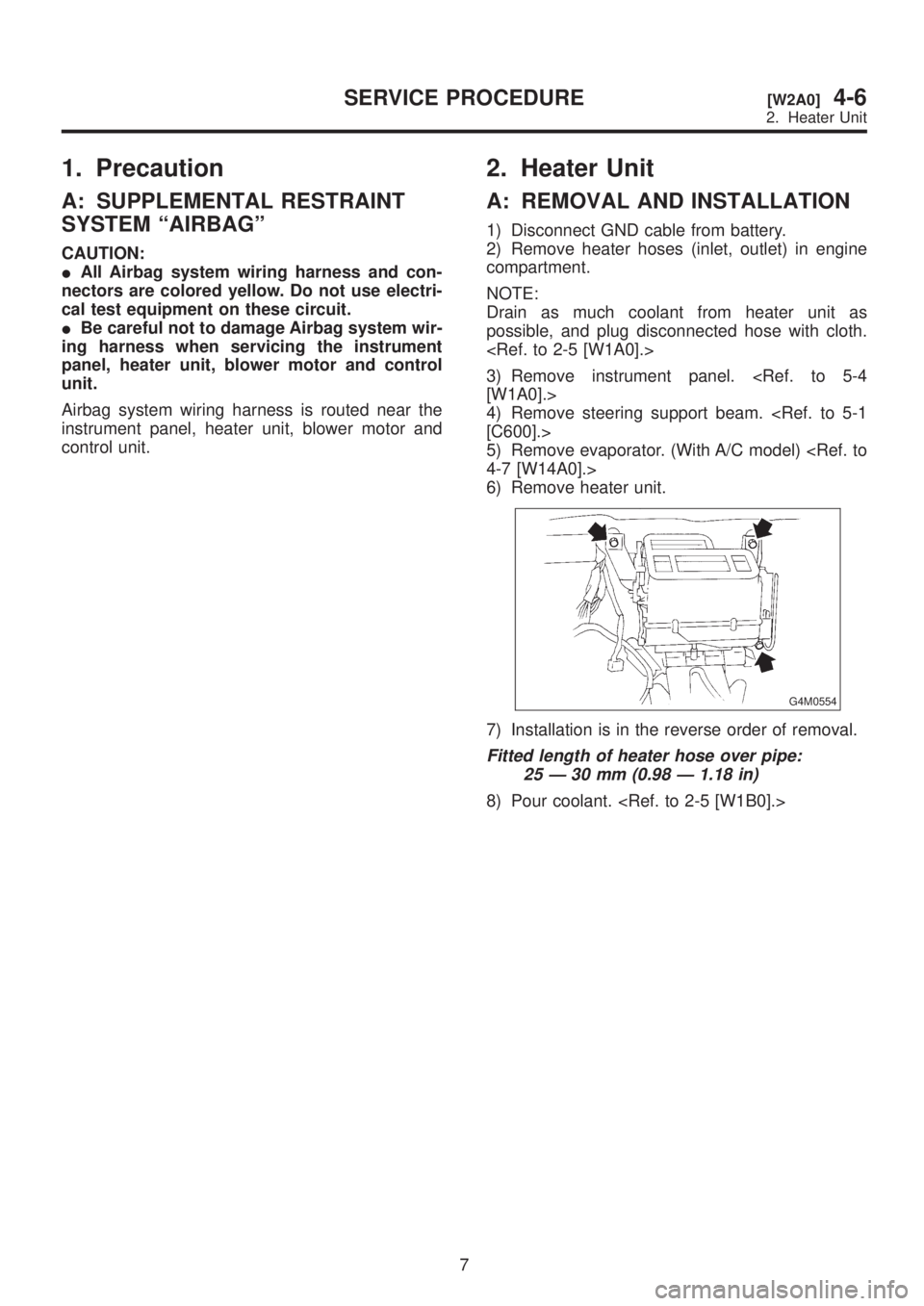
6) Remove heater unit.
G4M0554
7) Installation is in the reverse order of removal.
Fitted length of heater hose over pipe:
25 Ð 30 mm (0.98 Ð 1.18 in)
8) Pour coolant.
7
[W2A0]4-6SERVICE PROCEDURE
2. Heater Unit
Page 968 of 1456
1. Precaution
A: SUPPLEMENTAL RESTRAINT
SYSTEM ªAIRBAGº
CAUTION:
IAll Airbag system wiring harness and con-
nectors are colored yellow. Do not use electri-
cal test equipment on these circuit.
IBe careful not to damage Airbag system wir-
ing harness when servicing the instrument
panel, heater unit, blower motor and control
unit.
Airbag system wiring harness is routed near the
instrument panel, heater unit, blower motor and
control unit.
2. Heater Unit
A: REMOVAL AND INSTALLATION
1) Disconnect GND cable from battery.
2) Remove heater hoses (inlet, outlet) in engine
compartment.
NOTE:
Drain as much coolant from heater unit as
possible, and plug disconnected hose with cloth.
3) Remove instrument panel.
4) Remove steering support beam.
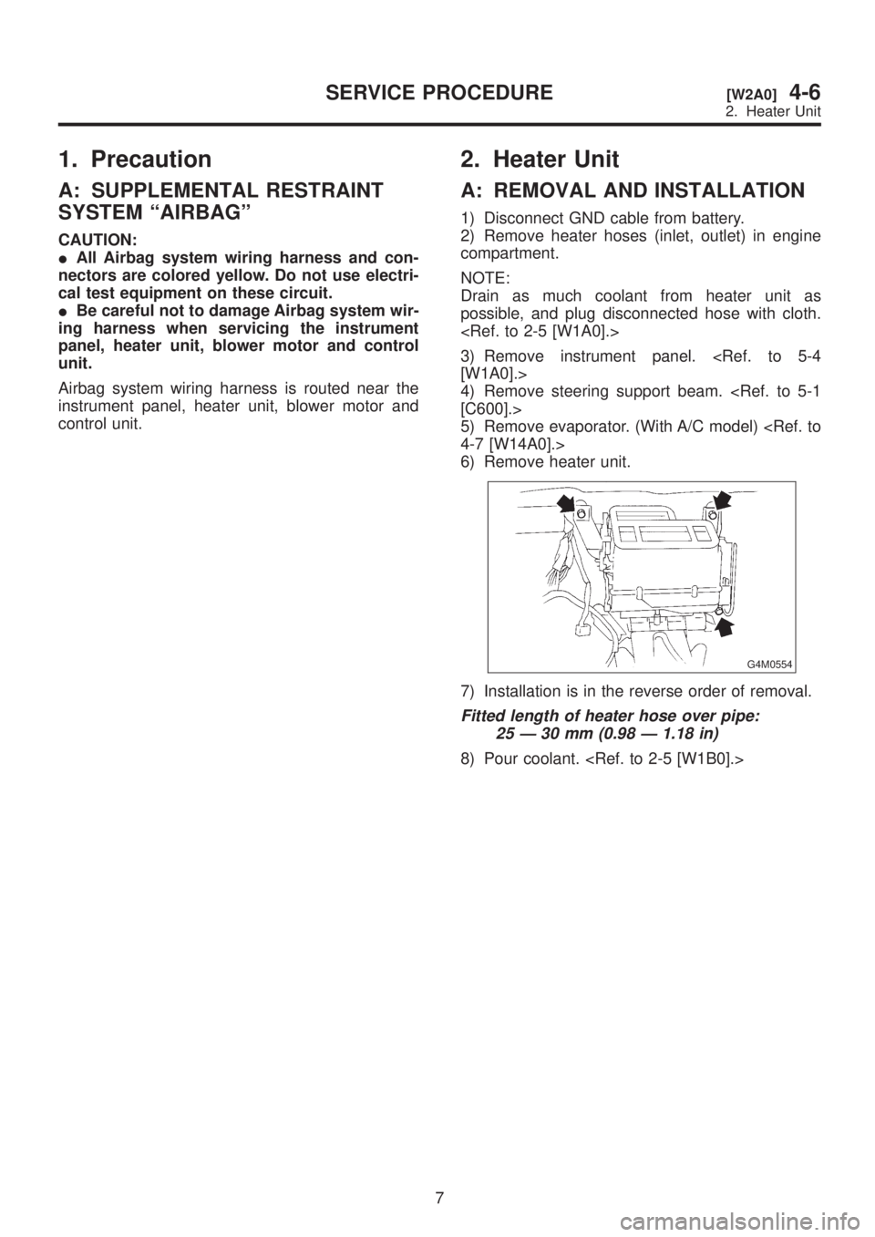
5) Remove evaporator. (With A/C model)
6) Remove heater unit.
G4M0554
7) Installation is in the reverse order of removal.
Fitted length of heater hose over pipe:
25 Ð 30 mm (0.98 Ð 1.18 in)
8) Pour coolant.
7
[W2A0]4-6SERVICE PROCEDURE
2. Heater Unit
Page 975 of 1456
![SUBARU LEGACY 1999 Service Repair Manual 6. Mode Door Motor
A: REMOVAL AND INSTALLATION
1) Remove instrument panel. <Ref. to 5-4 [W1A0].>
2) Remove mode door motor.
B4M0063
3) Installation is in the reverse order of removal.
B: INSPECTION
1) SUBARU LEGACY 1999 Service Repair Manual 6. Mode Door Motor
A: REMOVAL AND INSTALLATION
1) Remove instrument panel. <Ref. to 5-4 [W1A0].>
2) Remove mode door motor.
B4M0063
3) Installation is in the reverse order of removal.
B: INSPECTION
1)](/manual-img/17/57435/w960_57435-974.png)
6. Mode Door Motor
A: REMOVAL AND INSTALLATION
1) Remove instrument panel.
2) Remove mode door motor.
B4M0063
3) Installation is in the reverse order of removal.
B: INSPECTION
1) When approx. 12 V is applied to the mode door motor terminals, mode door motor operates as follows:
B4M1092A
2) Check mode door motor position switch.
When the mode door motor is moved to each mode position by using the mode selector switch, check if
continuity exists between each terminal as follows:
Mode selector switch positions Terminal No.
VENT 8 or 7
9 (GND) BI-LEV 6 or 7
HEAT 5 or 6
DEF/HEAT 4 or 5
DEF 3or4
12
4-6[W6A0]SERVICE PROCEDURE
6. Mode Door Motor