1999 SUBARU LEGACY airbag
[x] Cancel search: airbagPage 1180 of 1456
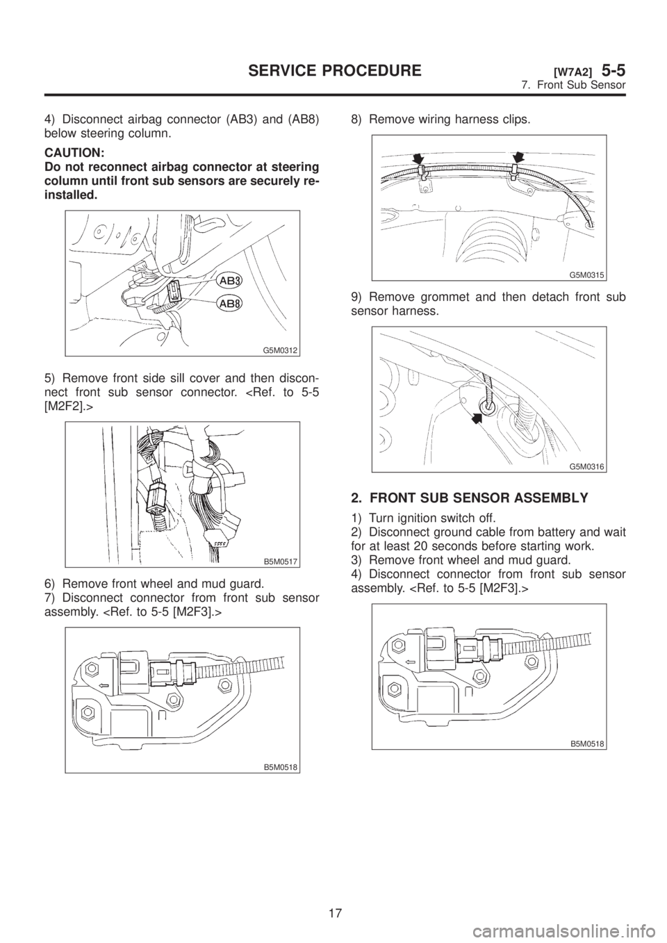
4) Disconnect airbag connector (AB3) and (AB8)
below steering column.
CAUTION:
Do not reconnect airbag connector at steering
column until front sub sensors are securely re-
installed.
G5M0312
5) Remove front side sill cover and then discon-
nect front sub sensor connector.
B5M0517
6) Remove front wheel and mud guard.
7) Disconnect connector from front sub sensor
assembly.
B5M0518
8) Remove wiring harness clips.
G5M0315
9) Remove grommet and then detach front sub
sensor harness.
G5M0316
2. FRONT SUB SENSOR ASSEMBLY
1) Turn ignition switch off.
2) Disconnect ground cable from battery and wait
for at least 20 seconds before starting work.
3) Remove front wheel and mud guard.
4) Disconnect connector from front sub sensor
assembly.
B5M0518
17
[W7A2]5-5SERVICE PROCEDURE
7. Front Sub Sensor
Page 1181 of 1456
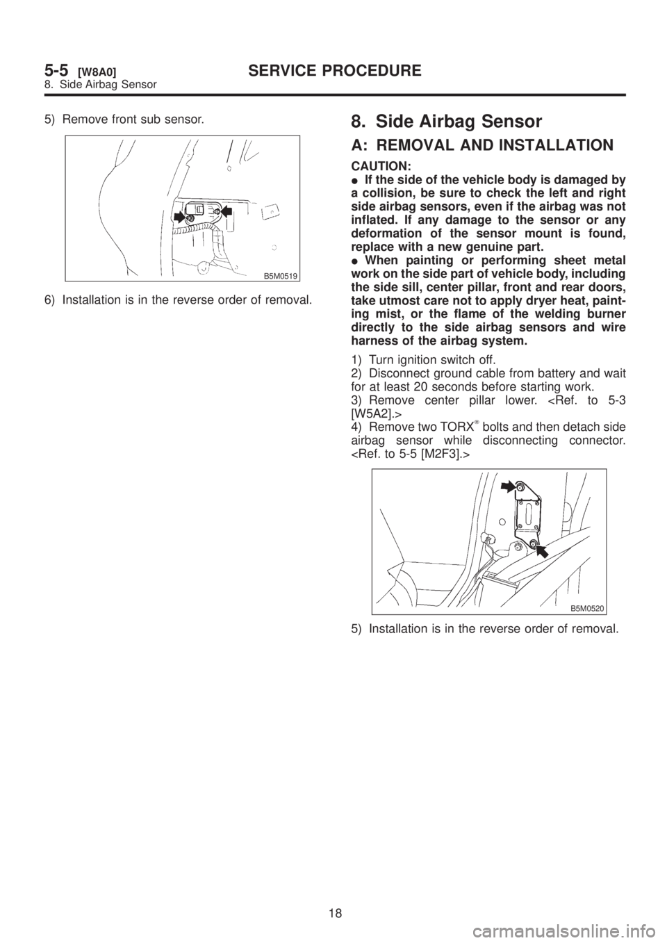
5) Remove front sub sensor.
B5M0519
6) Installation is in the reverse order of removal.
8. Side Airbag Sensor
A: REMOVAL AND INSTALLATION
CAUTION:
IIf the side of the vehicle body is damaged by
a collision, be sure to check the left and right
side airbag sensors, even if the airbag was not
inflated. If any damage to the sensor or any
deformation of the sensor mount is found,
replace with a new genuine part.
IWhen painting or performing sheet metal
work on the side part of vehicle body, including
the side sill, center pillar, front and rear doors,
take utmost care not to apply dryer heat, paint-
ing mist, or the flame of the welding burner
directly to the side airbag sensors and wire
harness of the airbag system.
1) Turn ignition switch off.
2) Disconnect ground cable from battery and wait
for at least 20 seconds before starting work.
3) Remove center pillar lower.
4) Remove two TORX
Tbolts and then detach side
airbag sensor while disconnecting connector.
B5M0520
5) Installation is in the reverse order of removal.
18
5-5[W8A0]SERVICE PROCEDURE
8. Side Airbag Sensor
Page 1182 of 1456
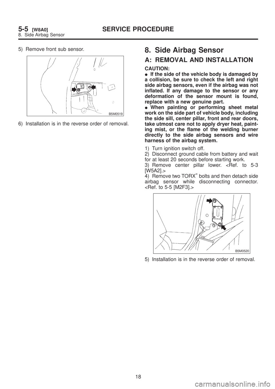
5) Remove front sub sensor.
B5M0519
6) Installation is in the reverse order of removal.
8. Side Airbag Sensor
A: REMOVAL AND INSTALLATION
CAUTION:
IIf the side of the vehicle body is damaged by
a collision, be sure to check the left and right
side airbag sensors, even if the airbag was not
inflated. If any damage to the sensor or any
deformation of the sensor mount is found,
replace with a new genuine part.
IWhen painting or performing sheet metal
work on the side part of vehicle body, including
the side sill, center pillar, front and rear doors,
take utmost care not to apply dryer heat, paint-
ing mist, or the flame of the welding burner
directly to the side airbag sensors and wire
harness of the airbag system.
1) Turn ignition switch off.
2) Disconnect ground cable from battery and wait
for at least 20 seconds before starting work.
3) Remove center pillar lower.
4) Remove two TORX
Tbolts and then detach side
airbag sensor while disconnecting connector.
B5M0520
5) Installation is in the reverse order of removal.
18
5-5[W8A0]SERVICE PROCEDURE
8. Side Airbag Sensor
Page 1226 of 1456
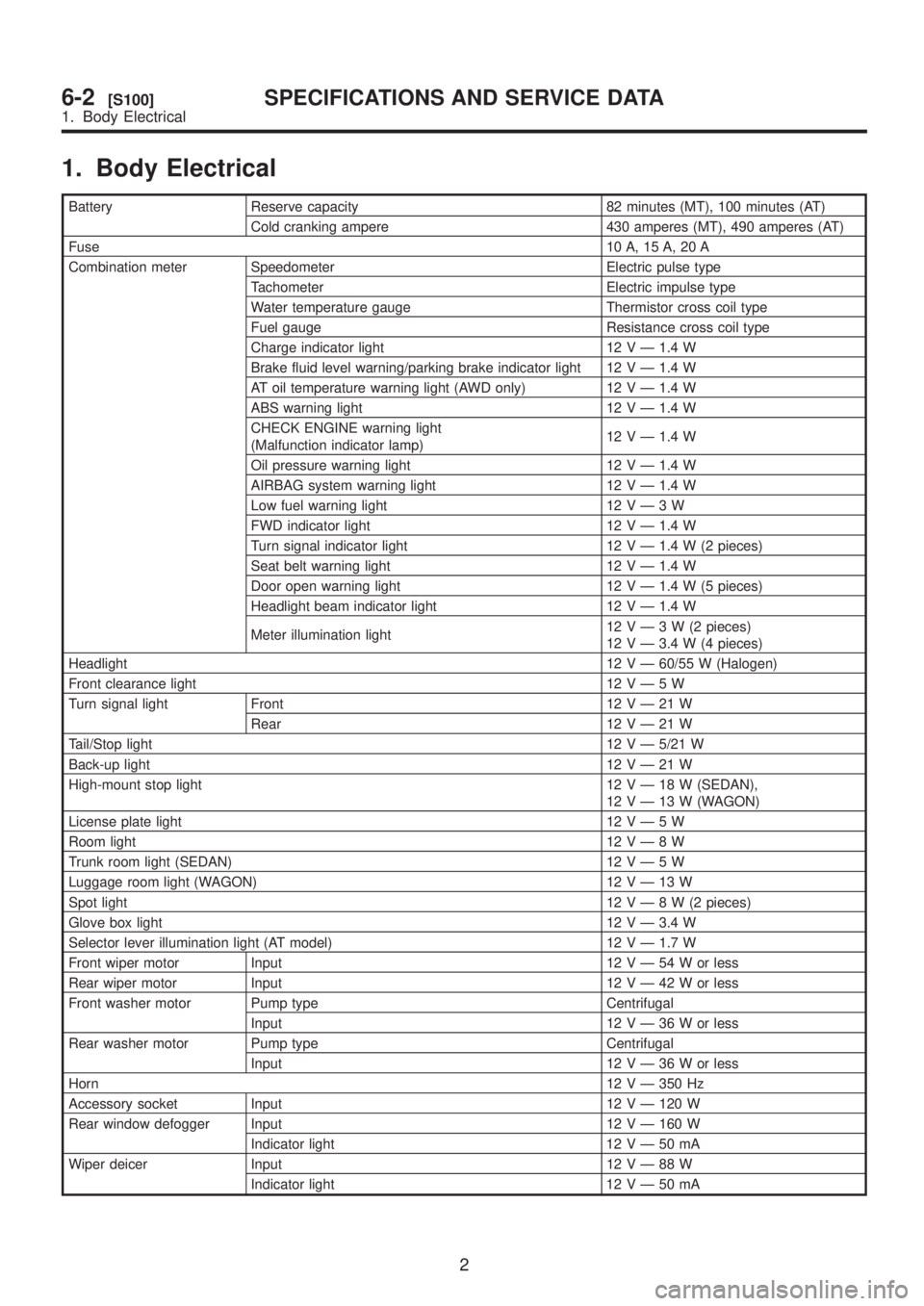
1. Body Electrical
Battery Reserve capacity 82 minutes (MT), 100 minutes (AT)
Cold cranking ampere 430 amperes (MT), 490 amperes (AT)
Fuse10 A, 15 A, 20 A
Combination meter Speedometer Electric pulse type
Tachometer Electric impulse type
Water temperature gauge Thermistor cross coil type
Fuel gauge Resistance cross coil type
Charge indicator light 12 V Ð 1.4 W
Brake fluid level warning/parking brake indicator light 12 V Ð 1.4 W
AT oil temperature warning light (AWD only) 12 V Ð 1.4 W
ABS warning light 12 V Ð 1.4 W
CHECK ENGINE warning light
(Malfunction indicator lamp)12 V Ð 1.4 W
Oil pressure warning light 12 V Ð 1.4 W
AIRBAG system warning light 12 V Ð 1.4 W
Low fuel warning light 12VÐ3W
FWD indicator light 12 V Ð 1.4 W
Turn signal indicator light 12 V Ð 1.4 W (2 pieces)
Seat belt warning light 12 V Ð 1.4 W
Door open warning light 12 V Ð 1.4 W (5 pieces)
Headlight beam indicator light 12 V Ð 1.4 W
Meter illumination light12VÐ3W(2pieces)
12 V Ð 3.4 W (4 pieces)
Headlight12 V Ð 60/55 W (Halogen)
Front clearance light 12VÐ5W
Turn signal light Front 12VÐ21W
Rear 12VÐ21W
Tail/Stop light12 V Ð 5/21 W
Back-up light12VÐ21W
High-mount stop light 12VÐ18W(SEDAN),
12VÐ13W(WAGON)
License plate light 12VÐ5W
Room light12VÐ8W
Trunk room light (SEDAN) 12VÐ5W
Luggage room light (WAGON) 12VÐ13W
Spot light12VÐ8W(2pieces)
Glove box light 12 V Ð 3.4 W
Selector lever illumination light (AT model) 12 V Ð 1.7 W
Front wiper motor Input 12VÐ54Worless
Rear wiper motor Input 12VÐ42Worless
Front washer motor Pump type Centrifugal
Input 12VÐ36Worless
Rear washer motor Pump type Centrifugal
Input 12VÐ36Worless
Horn12 V Ð 350 Hz
Accessory socket Input 12 V Ð 120 W
Rear window defogger Input 12 V Ð 160 W
Indicator light 12VÐ50mA
Wiper deicer Input 12VÐ88W
Indicator light 12VÐ50mA
2
6-2[S100]SPECIFICATIONS AND SERVICE DATA
1. Body Electrical
Page 1227 of 1456
1. Precaution
IBefore disassembling or reassembling parts,
always disconnect battery ground cable. When
repairing radio, control modules, etc. which are
provided with memory functions, record
memory contents before disconnecting battery
ground cable. Otherwise, these contents are
cancelled upon disconnection.
IReassemble parts in reverse order of disas-
sembly procedure unless otherwise indicated.
IAdjust parts to specifications contained in
this manual if so designated.
IConnect connectors and hoses securely dur-
ing reassembly.
IAfter reassembly, ensure functional parts
operate smoothly.
CAUTION:
IAirbag system wiring harness is routed near
the electrical parts and switch.
IAll Airbag system wiring harness and con-
nectors are colored yellow. Do not use electri-
cal test equipment on these circuits.
IBe careful not to damage Airbag system wir-
ing harness when servicing the ignition key
cylinder.
2. Battery
A: REMOVAL AND INSTALLATION
1. BATTERY
1) Disconnect the positive (+) terminal after dis-
connecting the negative (þ) terminal of battery.
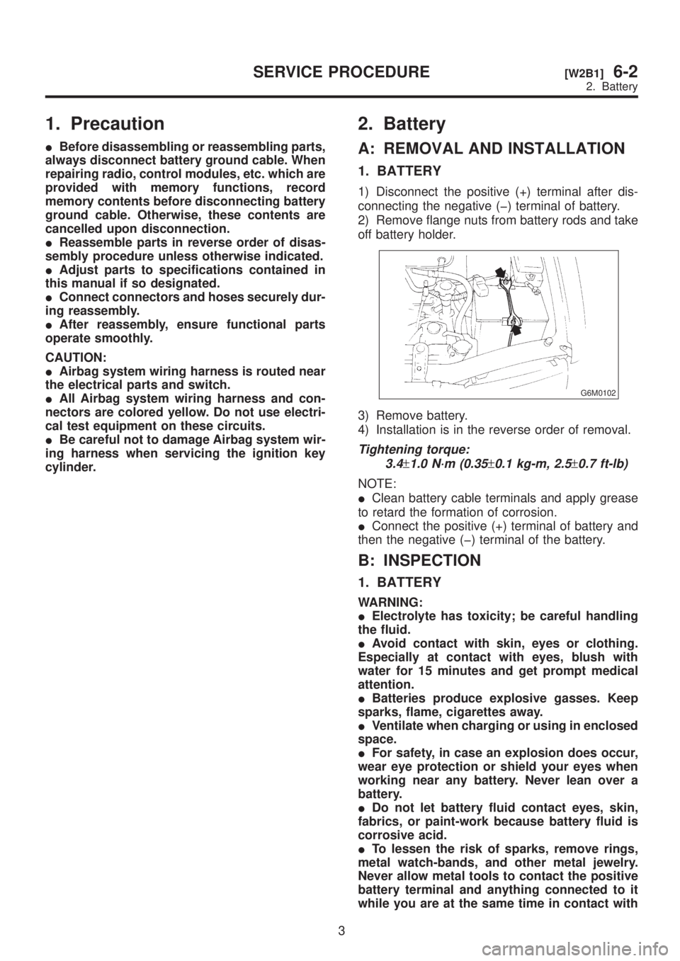
2) Remove flange nuts from battery rods and take
off battery holder.
G6M0102
3) Remove battery.
4) Installation is in the reverse order of removal.
Tightening torque:
3.4
±1.0 N´m (0.35±0.1 kg-m, 2.5±0.7 ft-lb)
NOTE:
IClean battery cable terminals and apply grease
to retard the formation of corrosion.
IConnect the positive (+) terminal of battery and
then the negative (þ) terminal of the battery.
B: INSPECTION
1. BATTERY
WARNING:
IElectrolyte has toxicity; be careful handling
the fluid.
IAvoid contact with skin, eyes or clothing.
Especially at contact with eyes, blush with
water for 15 minutes and get prompt medical
attention.
IBatteries produce explosive gasses. Keep
sparks, flame, cigarettes away.
IVentilate when charging or using in enclosed
space.
IFor safety, in case an explosion does occur,
wear eye protection or shield your eyes when
working near any battery. Never lean over a
battery.
IDo not let battery fluid contact eyes, skin,
fabrics, or paint-work because battery fluid is
corrosive acid.
ITo lessen the risk of sparks, remove rings,
metal watch-bands, and other metal jewelry.
Never allow metal tools to contact the positive
battery terminal and anything connected to it
while you are at the same time in contact with
3
[W2B1]6-2SERVICE PROCEDURE
2. Battery
Page 1228 of 1456
1. Precaution
IBefore disassembling or reassembling parts,
always disconnect battery ground cable. When
repairing radio, control modules, etc. which are
provided with memory functions, record
memory contents before disconnecting battery
ground cable. Otherwise, these contents are
cancelled upon disconnection.
IReassemble parts in reverse order of disas-
sembly procedure unless otherwise indicated.
IAdjust parts to specifications contained in
this manual if so designated.
IConnect connectors and hoses securely dur-
ing reassembly.
IAfter reassembly, ensure functional parts
operate smoothly.
CAUTION:
IAirbag system wiring harness is routed near
the electrical parts and switch.
IAll Airbag system wiring harness and con-
nectors are colored yellow. Do not use electri-
cal test equipment on these circuits.
IBe careful not to damage Airbag system wir-
ing harness when servicing the ignition key
cylinder.
2. Battery
A: REMOVAL AND INSTALLATION
1. BATTERY
1) Disconnect the positive (+) terminal after dis-
connecting the negative (þ) terminal of battery.
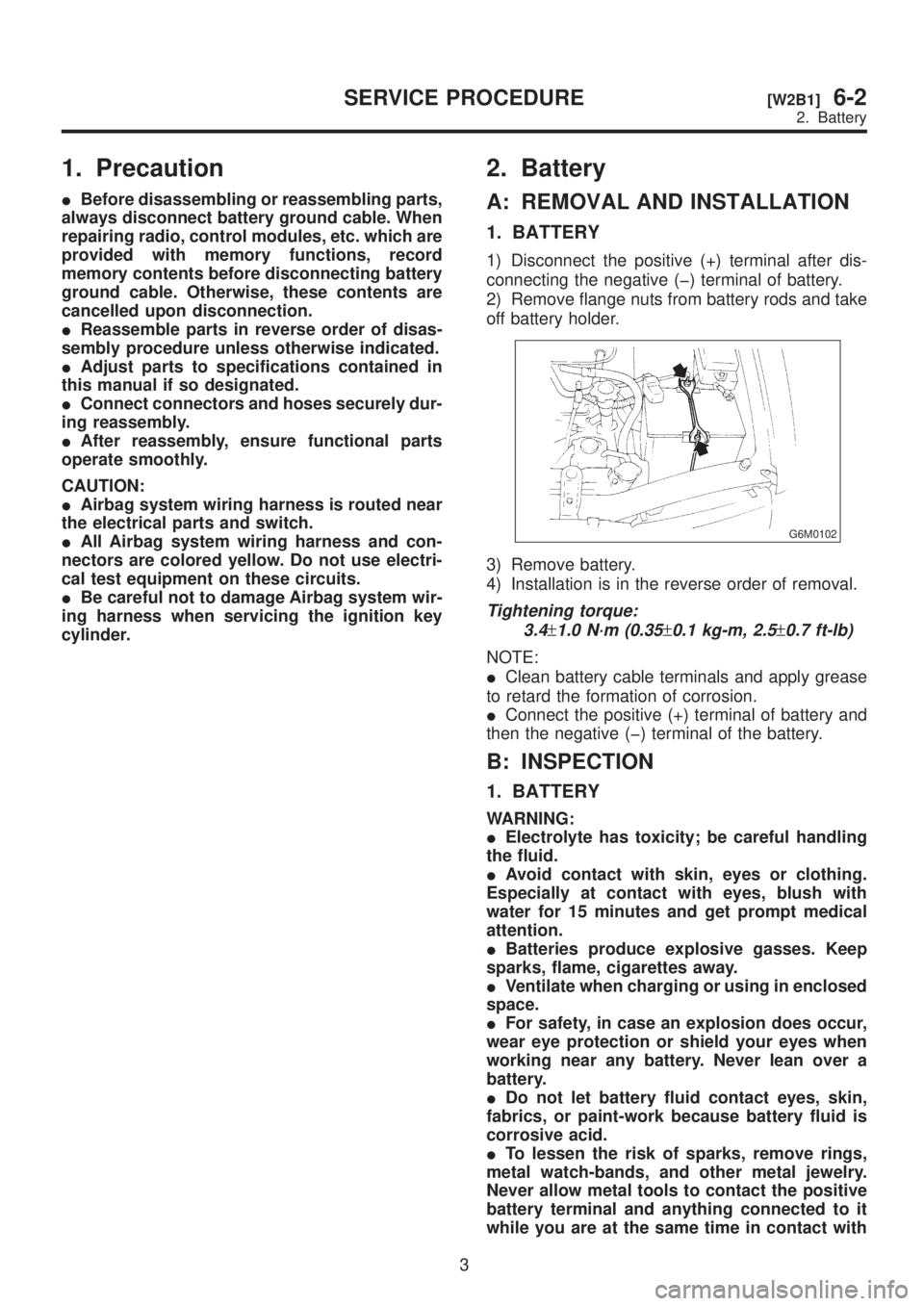
2) Remove flange nuts from battery rods and take
off battery holder.
G6M0102
3) Remove battery.
4) Installation is in the reverse order of removal.
Tightening torque:
3.4
±1.0 N´m (0.35±0.1 kg-m, 2.5±0.7 ft-lb)
NOTE:
IClean battery cable terminals and apply grease
to retard the formation of corrosion.
IConnect the positive (+) terminal of battery and
then the negative (þ) terminal of the battery.
B: INSPECTION
1. BATTERY
WARNING:
IElectrolyte has toxicity; be careful handling
the fluid.
IAvoid contact with skin, eyes or clothing.
Especially at contact with eyes, blush with
water for 15 minutes and get prompt medical
attention.
IBatteries produce explosive gasses. Keep
sparks, flame, cigarettes away.
IVentilate when charging or using in enclosed
space.
IFor safety, in case an explosion does occur,
wear eye protection or shield your eyes when
working near any battery. Never lean over a
battery.
IDo not let battery fluid contact eyes, skin,
fabrics, or paint-work because battery fluid is
corrosive acid.
ITo lessen the risk of sparks, remove rings,
metal watch-bands, and other metal jewelry.
Never allow metal tools to contact the positive
battery terminal and anything connected to it
while you are at the same time in contact with
3
[W2B1]6-2SERVICE PROCEDURE
2. Battery
Page 1232 of 1456
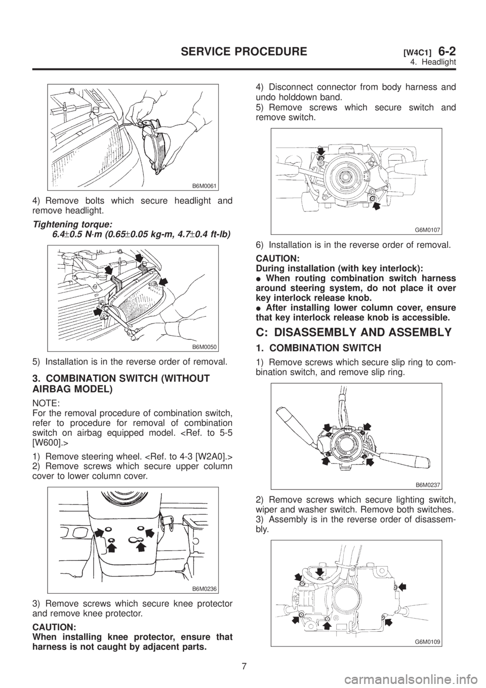
B6M0061
4) Remove bolts which secure headlight and
remove headlight.
Tightening torque:
6.4
±0.5 N´m (0.65±0.05 kg-m, 4.7±0.4 ft-lb)
B6M0050
5) Installation is in the reverse order of removal.
3. COMBINATION SWITCH (WITHOUT
AIRBAG MODEL)
NOTE:
For the removal procedure of combination switch,
refer to procedure for removal of combination
switch on airbag equipped model.
1) Remove steering wheel.
2) Remove screws which secure upper column
cover to lower column cover.
B6M0236
3) Remove screws which secure knee protector
and remove knee protector.
CAUTION:
When installing knee protector, ensure that
harness is not caught by adjacent parts.4) Disconnect connector from body harness and
undo holddown band.
5) Remove screws which secure switch and
remove switch.
G6M0107
6) Installation is in the reverse order of removal.
CAUTION:
During installation (with key interlock):
IWhen routing combination switch harness
around steering system, do not place it over
key interlock release knob.
IAfter installing lower column cover, ensure
that key interlock release knob is accessible.
C: DISASSEMBLY AND ASSEMBLY
1. COMBINATION SWITCH
1) Remove screws which secure slip ring to com-
bination switch, and remove slip ring.
B6M0237
2) Remove screws which secure lighting switch,
wiper and washer switch. Remove both switches.
3) Assembly is in the reverse order of disassem-
bly.
G6M0109
7
[W4C1]6-2SERVICE PROCEDURE
4. Headlight
Page 1272 of 1456
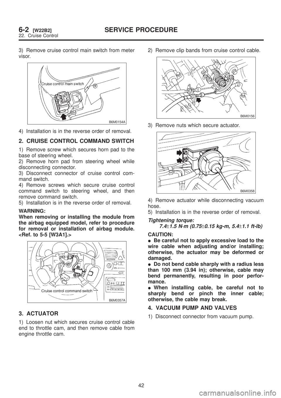
3) Remove cruise control main switch from meter
visor.
B6M0154A
4) Installation is in the reverse order of removal.
2. CRUISE CONTROL COMMAND SWITCH
1) Remove screw which secures horn pad to the
base of steering wheel.
2) Remove horn pad from steering wheel while
disconnecting connector.
3) Disconnect connector of cruise control com-
mand switch.
4) Remove screws which secure cruise control
command switch to steering wheel, and then
remove command switch.
5) Installation is in the reverse order of removal.
WARNING:
When removing or installing the module from
the airbag equipped model, refer to procedure
for removal or installation of airbag module.
B6M0357A
3. ACTUATOR
1) Loosen nut which secures cruise control cable
end to throttle cam, and then remove cable from
engine throttle cam.2) Remove clip bands from cruise control cable.
B6M0156
3) Remove nuts which secure actuator.
B6M0358
4) Remove actuator while disconnecting vacuum
hose.
5) Installation is in the reverse order of removal.
Tightening torque:
7.4
±1.5 N´m (0.75±0.15 kg-m, 5.4±1.1 ft-lb)
CAUTION:
IBe careful not to apply excessive load to the
wire cable when adjusting and/or installing;
otherwise, the actuator may be deformed or
damaged.
IDo not bend cable sharply with a radius less
than 100 mm (3.94 in); otherwise, cable may
bend permanently, resulting in poor perfor-
mance.
IWhen installing cable, be careful not to
sharply bend or pinch the inner cable;
otherwise, the cable may break.
4. VACUUM PUMP AND VALVES
1) Disconnect connector from vacuum pump.
42
6-2[W22B2]SERVICE PROCEDURE
22. Cruise Control