Page 42 of 1456
S2M0242
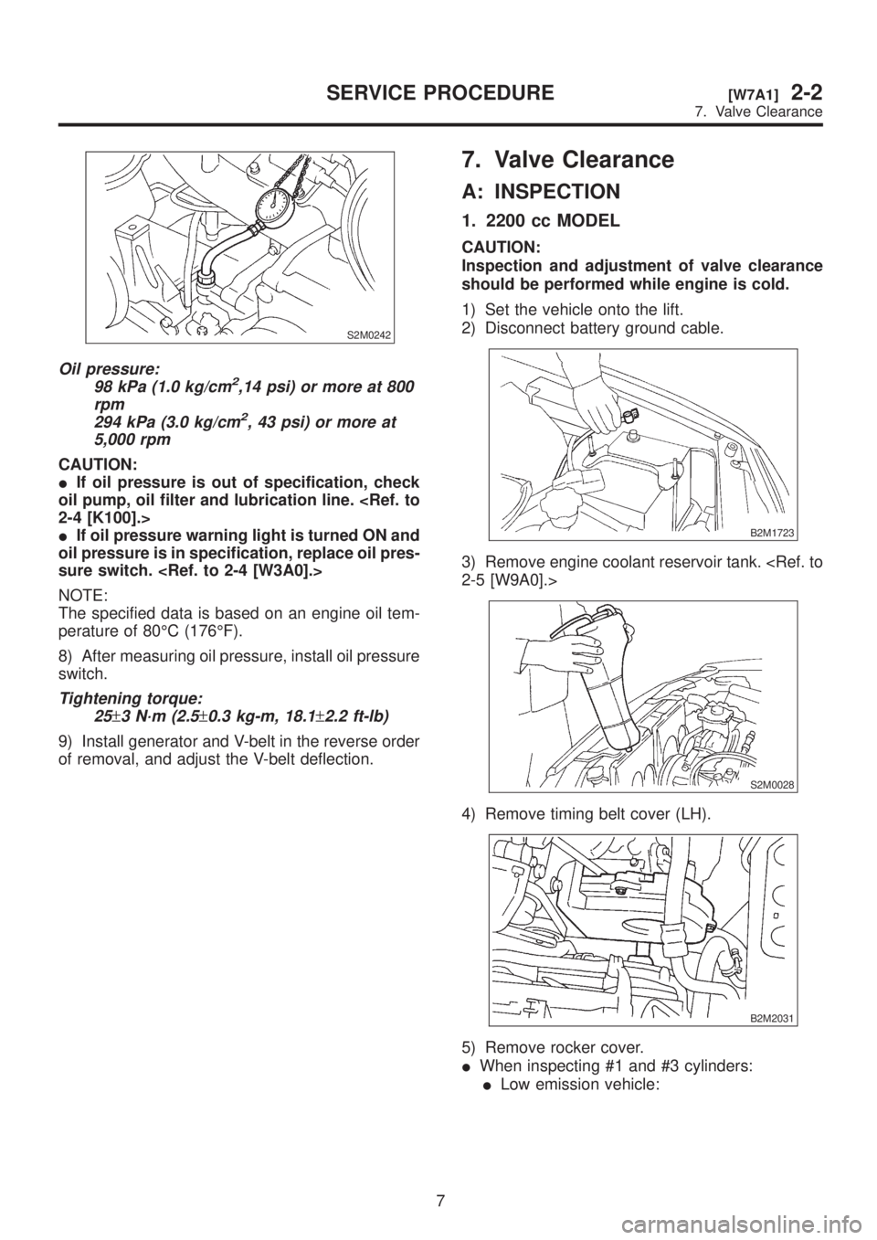
Oil pressure:
98 kPa (1.0 kg/cm2,14 psi) or more at 800
rpm
294 kPa (3.0 kg/cm
2, 43 psi) or more at
5,000 rpm
CAUTION:
IIf oil pressure is out of specification, check
oil pump, oil filter and lubrication line.
2-4 [K100].>
IIf oil pressure warning light is turned ON and
oil pressure is in specification, replace oil pres-
sure switch.
NOTE:
The specified data is based on an engine oil tem-
perature of 80ÉC (176ÉF).
8) After measuring oil pressure, install oil pressure
switch.
Tightening torque:
25
±3 N´m (2.5±0.3 kg-m, 18.1±2.2 ft-lb)
9) Install generator and V-belt in the reverse order
of removal, and adjust the V-belt deflection.
7. Valve Clearance
A: INSPECTION
1. 2200 cc MODEL
CAUTION:
Inspection and adjustment of valve clearance
should be performed while engine is cold.
1) Set the vehicle onto the lift.
2) Disconnect battery ground cable.
B2M1723
3) Remove engine coolant reservoir tank.
2-5 [W9A0].>
S2M0028
4) Remove timing belt cover (LH).
B2M2031
5) Remove rocker cover.
IWhen inspecting #1 and #3 cylinders:
ILow emission vehicle:
7
[W7A1]2-2SERVICE PROCEDURE
7. Valve Clearance
Page 43 of 1456
S2M0242
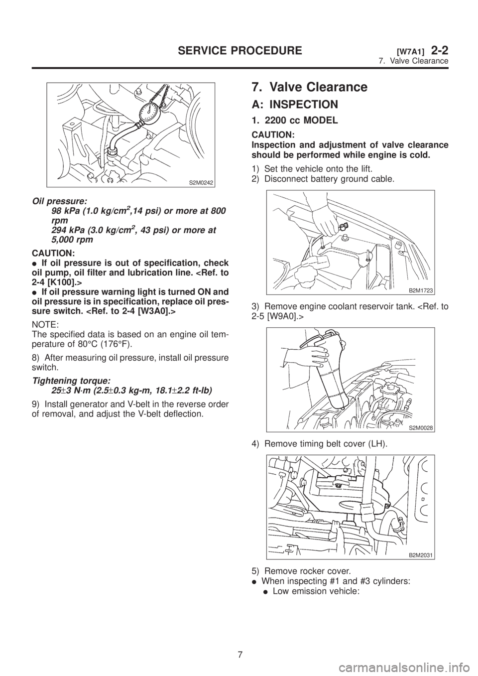
Oil pressure:
98 kPa (1.0 kg/cm2,14 psi) or more at 800
rpm
294 kPa (3.0 kg/cm
2, 43 psi) or more at
5,000 rpm
CAUTION:
IIf oil pressure is out of specification, check
oil pump, oil filter and lubrication line.
2-4 [K100].>
IIf oil pressure warning light is turned ON and
oil pressure is in specification, replace oil pres-
sure switch.
NOTE:
The specified data is based on an engine oil tem-
perature of 80ÉC (176ÉF).
8) After measuring oil pressure, install oil pressure
switch.
Tightening torque:
25
±3 N´m (2.5±0.3 kg-m, 18.1±2.2 ft-lb)
9) Install generator and V-belt in the reverse order
of removal, and adjust the V-belt deflection.
7. Valve Clearance
A: INSPECTION
1. 2200 cc MODEL
CAUTION:
Inspection and adjustment of valve clearance
should be performed while engine is cold.
1) Set the vehicle onto the lift.
2) Disconnect battery ground cable.
B2M1723
3) Remove engine coolant reservoir tank.
2-5 [W9A0].>
S2M0028
4) Remove timing belt cover (LH).
B2M2031
5) Remove rocker cover.
IWhen inspecting #1 and #3 cylinders:
ILow emission vehicle:
7
[W7A1]2-2SERVICE PROCEDURE
7. Valve Clearance
Page 65 of 1456
1. General Precautions
A: GENERAL PRECAUTIONS
1) Before disassembling engine, place it on ST3.
ST1 498457000 ENGINE STAND ADAPTER
RH
ST2 498457100 ENGINE STAND ADAPTER
LH
ST3 499817000 ENGINE STAND
B2M2582A
2) All parts should be thoroughly cleaned, paying
special attention to the engine oil passages, pis-
tons and bearings.
3) Rotating parts and sliding parts such as piston,
bearing and gear should be coated with oil prior to
assembly.
4) Be careful not to let oil, grease or coolant con-
tact the timing belt, clutch disc and flywheel.
5) All removed parts, if to be reused, should be
reinstalled in the original positions and directions.
6) All removed parts, if to be reused, should be
reinstalled in the original positions and directions.
7) Bolts, nuts and washers should be replaced
with new ones as required.
8) Even if necessary inspections have been made
in advance, proceed with assembly work while
making rechecks.
12
2-3a[W1A0]SERVICE PROCEDURE
1. General Precautions
Page 71 of 1456
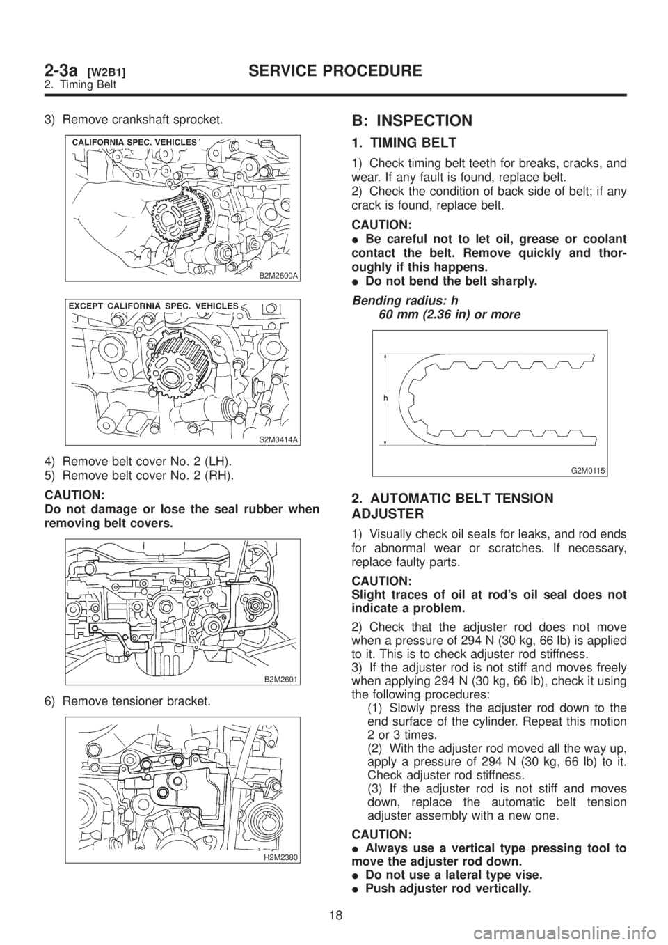
3) Remove crankshaft sprocket.
B2M2600A
S2M0414A
4) Remove belt cover No. 2 (LH).
5) Remove belt cover No. 2 (RH).
CAUTION:
Do not damage or lose the seal rubber when
removing belt covers.
B2M2601
6) Remove tensioner bracket.
H2M2380
B: INSPECTION
1. TIMING BELT
1) Check timing belt teeth for breaks, cracks, and
wear. If any fault is found, replace belt.
2) Check the condition of back side of belt; if any
crack is found, replace belt.
CAUTION:
IBe careful not to let oil, grease or coolant
contact the belt. Remove quickly and thor-
oughly if this happens.
IDo not bend the belt sharply.
Bending radius: h
60 mm (2.36 in) or more
G2M0115
2. AUTOMATIC BELT TENSION
ADJUSTER
1) Visually check oil seals for leaks, and rod ends
for abnormal wear or scratches. If necessary,
replace faulty parts.
CAUTION:
Slight traces of oil at rod's oil seal does not
indicate a problem.
2) Check that the adjuster rod does not move
when a pressure of 294 N (30 kg, 66 lb) is applied
to it. This is to check adjuster rod stiffness.
3) If the adjuster rod is not stiff and moves freely
when applying 294 N (30 kg, 66 lb), check it using
the following procedures:
(1) Slowly press the adjuster rod down to the
end surface of the cylinder. Repeat this motion
2 or 3 times.
(2) With the adjuster rod moved all the way up,
apply a pressure of 294 N (30 kg, 66 lb) to it.
Check adjuster rod stiffness.
(3) If the adjuster rod is not stiff and moves
down, replace the automatic belt tension
adjuster assembly with a new one.
CAUTION:
IAlways use a vertical type pressing tool to
move the adjuster rod down.
IDo not use a lateral type vise.
IPush adjuster rod vertically.
18
2-3a[W2B1]SERVICE PROCEDURE
2. Timing Belt
Page 83 of 1456

C: INSPECTION
1. VALVE ROCKER ARM
1) Measure inside diameter of valve rocker arm
and outside diameter of valve rocker shaft, and
determine the difference between the two (= oil
clearance).
Clearance between arm and shaft:
Standard
0.020 Ð 0.054 mm (0.0008 Ð 0.0021 in)
Limit
0.10 mm (0.0039 in)
IIf oil clearance exceeds specifications, replace
valve rocker arm or shaft.
NOTE:
Replace valve rocker arm or shaft, whichever
shows greater amount of wear.
Rocker arm inside diameter:
22.020 Ð 22.041 mm (0.8669 Ð 0.8678 in)
Rocker shaft diameter:
21.987 Ð 22.000 mm (0.8656 Ð 0.8661 in)
B2M0072
B2M0073
2) Measure inside diameter of rocker shaft sup-
port and outside diameter of valve rocker shaft,
and determine the difference between the two (=
oil clearance).
Clearance between support and shaft:
Standard
0.005 Ð 0.039 mm (0.0002 Ð 0.0015 in)
Limit
0.05 mm (0.0020 in)
IIf oil clearance exceeds specifications, replace
rocker shaft support or shaft.
NOTE:
Replace rocker shaft support or shaft, whichever
shows greater amount of wear.
Rocker shaft support inside diameter:
22.005 Ð 22.026 mm (0.8663 Ð 0.8672 in)
Rocker shaft diameter:
21.987 Ð 22.000 mm (0.8656 Ð 0.8661 in)
3) If cam or valve contact surface of valve rocker
arm is worn or dented excessively, replace valve
rocker arm.
4) Check that valve rocker arm roller rotates
smoothly. If not, replace valve rocker arm.
2. INTAKE AND EXHAUST VALVE
ROCKER SHAFT
Visually check oil relief valve of shaft end for any
of the following abnormalities.
IBreaks in check ball body
IForeign particles caught in valve spring
IOil leakage at check ball
CAUTION:
Repair or replace valve rocker shaft as neces-
sary.
29
[W3C2]2-3aSERVICE PROCEDURE
3. Valve Rocker Assembly
Page 88 of 1456
(1) Remove valve rocker assembly RH.
B2M2615
(2) Remove bolts (a) through (b) in alphabetical
sequence.
B2M2612A
(3) Equally loosen bolts (c) through (j) all the
way in alphabetical sequence.
B2M2612A
(4) Remove bolts (k) through (p) in alphabetical
sequence using ST.
ST 499497000 TORX PLUS
B2M2612A
(5) Remove camshaft cap.
B2M2613
2) Remove camshaft (RH).
3) Remove oil seal.
4) Remove plug from rear side of camshaft (RH).
CAUTION:
IDo not remove oil seal unless necessary.
IDo not scratch journal surface when remov-
ing oil seal.
B: INSPECTION
1. CAMSHAFT
1) Measure the bend, and repair or replace if nec-
essary.
Limit:
0.020 mm (0.0008 in)
B2M2617
2) Check journal for damage and wear. Replace if
faulty.
34
2-3a[W4B1]SERVICE PROCEDURE
4. Camshaft
Page 89 of 1456
3) Measure outside diameter of camshaft journal
and inside diameter of cylinder head journal, and
determine the difference between the two (= oilclearance). If oil clearance exceeds specifications,
replace camshaft or cylinder head as necessary.
Unit: mm (in)
Clearance at journalStandard 0.055 Ð 0.090 (0.0022 Ð 0.0035)
Limit 0.118 (0.0046)
Camshaft journal O.D. 31.928 Ð 31.945 (1.2570 Ð 1.2577)
Journal hole I.D. 32.000 Ð 32.018 (1.2598 Ð 1.2605)
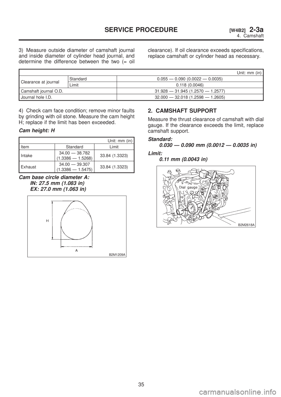
4) Check cam face condition; remove minor faults
by grinding with oil stone. Measure the cam height
H; replace if the limit has been exceeded.
Cam height: H
Unit: mm (in)
Item Standard Limit
Intake34.00 Ð 38.782
(1.3386 Ð 1.5268)33.84 (1.3323)
Exhaust34.00 Ð 39.307
(1.3386 Ð 1.5475)33.84 (1.3323)
Cam base circle diameter A:
IN: 27.5 mm (1.083 in)
EX: 27.0 mm (1.063 in)
B2M1209A
2. CAMSHAFT SUPPORT
Measure the thrust clearance of camshaft with dial
gauge. If the clearance exceeds the limit, replace
camshaft support.
Standard:
0.030 Ð 0.090 mm (0.0012 Ð 0.0035 in)
Limit:
0.11 mm (0.0043 in)
B2M2618A
35
[W4B2]2-3aSERVICE PROCEDURE
4. Camshaft
Page 99 of 1456
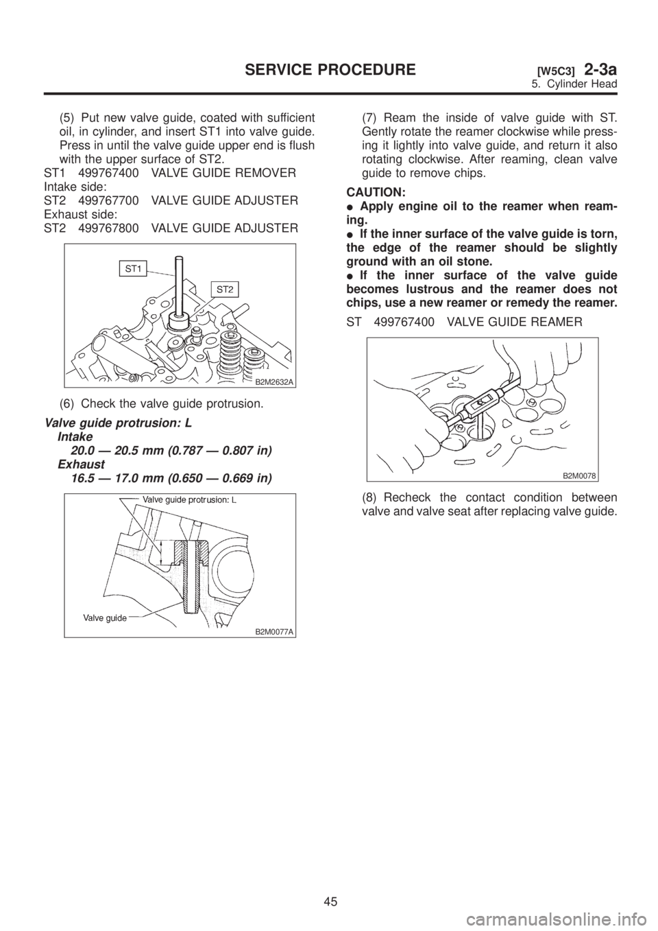
(5) Put new valve guide, coated with sufficient
oil, in cylinder, and insert ST1 into valve guide.
Press in until the valve guide upper end is flush
with the upper surface of ST2.
ST1 499767400 VALVE GUIDE REMOVER
Intake side:
ST2 499767700 VALVE GUIDE ADJUSTER
Exhaust side:
ST2 499767800 VALVE GUIDE ADJUSTER
B2M2632A
(6) Check the valve guide protrusion.
Valve guide protrusion: L
Intake
20.0 Ð 20.5 mm (0.787 Ð 0.807 in)
Exhaust
16.5 Ð 17.0 mm (0.650 Ð 0.669 in)
B2M0077A
(7) Ream the inside of valve guide with ST.
Gently rotate the reamer clockwise while press-
ing it lightly into valve guide, and return it also
rotating clockwise. After reaming, clean valve
guide to remove chips.
CAUTION:
IApply engine oil to the reamer when ream-
ing.
IIf the inner surface of the valve guide is torn,
the edge of the reamer should be slightly
ground with an oil stone.
IIf the inner surface of the valve guide
becomes lustrous and the reamer does not
chips, use a new reamer or remedy the reamer.
ST 499767400 VALVE GUIDE REAMER
B2M0078
(8) Recheck the contact condition between
valve and valve seat after replacing valve guide.
45
[W5C3]2-3aSERVICE PROCEDURE
5. Cylinder Head