Page 535 of 1456
C: LOCATION AND INSTALLING DIRECTION OF THRUST NEEDLE BEARING
B3M1016A
10
3-2[S1C0]SPECIFICATIONS AND SERVICE DATA
1. Automatic Transmission and Differential
Page 536 of 1456

No. Part Name Part NumberInside diameter
mm (in)Outside diameter
mm (in)Dimension
mm (in)Application
(1)Thrust needle
bearing806528050
806528060
806528070
806528080
806528090
80652810028.5 (1.122) 48 (1.89)4.1 (0.161)
4.3 (0.169)
4.5 (0.177)
4.7 (0.185)
4.9 (0.193)
5.1 (0.201)Adjusting total
end play
(2)Thrust needle
bearing806530040 30 (1.18) 47 (1.85) 3.8 (0.150)Place of high
clutch
(3)Thrust needle
bearing806551020 51 (2.01) 71 (2.80) 3.3 (0.130)Place of front sun
gear
(4)Thrust needle
bearing806535120 35 (1.38) 53 (2.09) 4.8 (0.189)Place of rear sun
gear
(5)Thrust needle
bearing806534060 35 (1.38) 53 (2.09) 3.3 (0.130)Place of rear sun
gear
(6)Thrust needle
bearing806558030 58 (2.28) 78 (3.07) 2.8 (0.110)Place of rear
internal gear
(7)Thrust needle
bearing806541020 39.7 (1.563) 54 (2.13) 3.6 (0.142)Place of one-way
clutch
(8)Thrust needle
bearing806536020
806535030
806535040
806535050
806535060
806535070
80653509036 (1.42) 53 (2.09)3.8 (0.150)
4.0 (0.157)
4.2 (0.165)
4.4 (0.173)
4.6 (0.181)
4.8 (0.189)
5.0 (0.197)Adjusting end play
of transfer clutch
D: FLUID PASSAGES
1. TRANSMISSION CASE (FRONT SIDE)
B3M0987A
(1) Low clutch pressure (2) Oil cooler inlet pressure (3) Low & reverse brake pressure
11
[S1D1]3-2SPECIFICATIONS AND SERVICE DATA
1. Automatic Transmission and Differential
Page 537 of 1456
2. TRANSMISSION CASE (LH SIDE)
B3M0988A
(1) Oil cooler outlet pressure
(2) Low & reverse brake pressure(3) Oil cooler inlet pressure
(4) Low clutch pressure(5) 2-4 brake pressure
3. TRANSMISSION CASE (REAR SIDE)
B3M0989A
(1) Pilot pressure (2) Line pressure
12
3-2[S1D2]SPECIFICATIONS AND SERVICE DATA
1. Automatic Transmission and Differential
Page 538 of 1456
4. OIL PUMP COVER
B3M0990A
(1) High clutch pressure
(2) Lock-up release pressure(3) Front lubricating hole
(4) Lock-up apply pressure(5) Reverse clutch pressure
5. OIL PUMP HOUSING
B3M0991A
(1) Oil pump outlet pressure
(2) Lock-up apply pressure
(3) Lock-up release pressure(4) High clutch pressure
(5) Drain
(6) Air breather(7) Reverse clutch pressure
13
[S1D5]3-2SPECIFICATIONS AND SERVICE DATA
1. Automatic Transmission and Differential
Page 539 of 1456
6. TRANSMISSION CASE
B3M0992A
(1) Oil pump inlet port
(2) Reverse clutch pressure
(3) Oil pump outlet port
(4) Lock-up apply pressure(5) Lock-up release pressure
(6) High clutch pressure
(7) Oil cooler outlet pressure
(8) Line pressure(9) Pilot pressure
(10) Low & reverse brake pressure
(11) Low clutch pressure
(12) 2-4 brake pressure
7. EXTENSION CASE
B3M0993A
14
3-2[S1D6]SPECIFICATIONS AND SERVICE DATA
1. Automatic Transmission and Differential
Page 570 of 1456

stall speed range on the tachometer scale.
3) Place the wheel chocks at the front and rear of
all wheels and engage the parking brake.
4) Move the manual linkage to ensure it operates
properly, and shift the select lever to the 2 range.
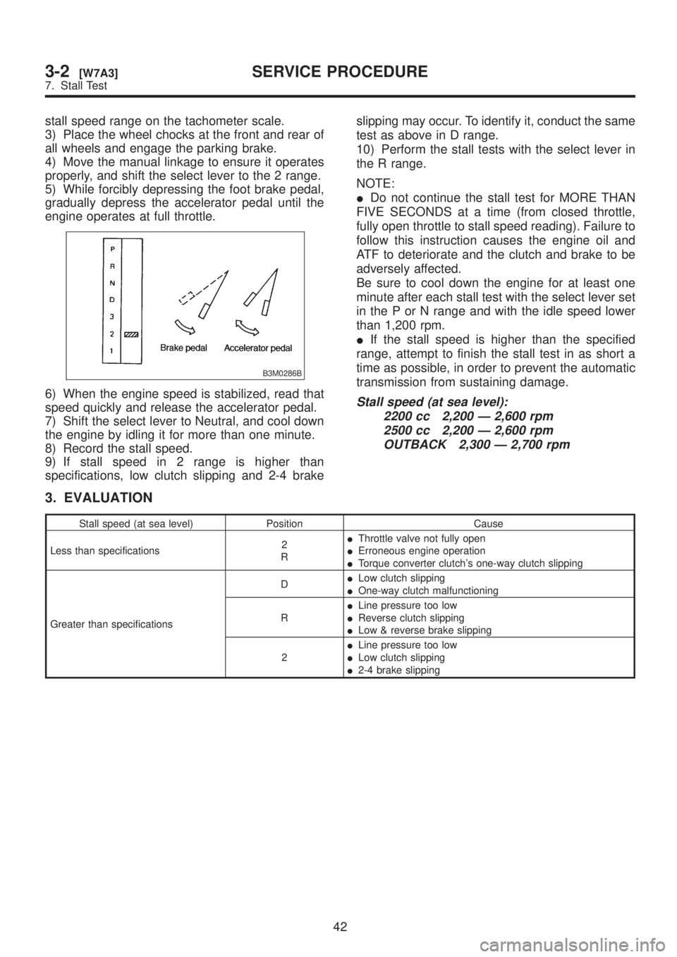
5) While forcibly depressing the foot brake pedal,
gradually depress the accelerator pedal until the
engine operates at full throttle.
B3M0286B
6) When the engine speed is stabilized, read that
speed quickly and release the accelerator pedal.
7) Shift the select lever to Neutral, and cool down
the engine by idling it for more than one minute.
8) Record the stall speed.
9) If stall speed in 2 range is higher than
specifications, low clutch slipping and 2-4 brakeslipping may occur. To identify it, conduct the same
test as above in D range.
10) Perform the stall tests with the select lever in
the R range.
NOTE:
IDo not continue the stall test for MORE THAN
FIVE SECONDS at a time (from closed throttle,
fully open throttle to stall speed reading). Failure to
follow this instruction causes the engine oil and
ATF to deteriorate and the clutch and brake to be
adversely affected.
Be sure to cool down the engine for at least one
minute after each stall test with the select lever set
in the P or N range and with the idle speed lower
than 1,200 rpm.
IIf the stall speed is higher than the specified
range, attempt to finish the stall test in as short a
time as possible, in order to prevent the automatic
transmission from sustaining damage.Stall speed (at sea level):
2200 cc 2,200 Ð 2,600 rpm
2500 cc 2,200 Ð 2,600 rpm
OUTBACK 2,300 Ð 2,700 rpm
3. EVALUATION
Stall speed (at sea level) Position Cause
Less than specifications2
RIThrottle valve not fully open
IErroneous engine operation
ITorque converter clutch's one-way clutch slipping
Greater than specificationsDILow clutch slipping
IOne-way clutch malfunctioning
RILine pressure too low
IReverse clutch slipping
ILow & reverse brake slipping
2ILine pressure too low
ILow clutch slipping
I2-4 brake slipping
42
3-2[W7A3]SERVICE PROCEDURE
7. Stall Test
Page 600 of 1456

7. EXTERNAL PARTS
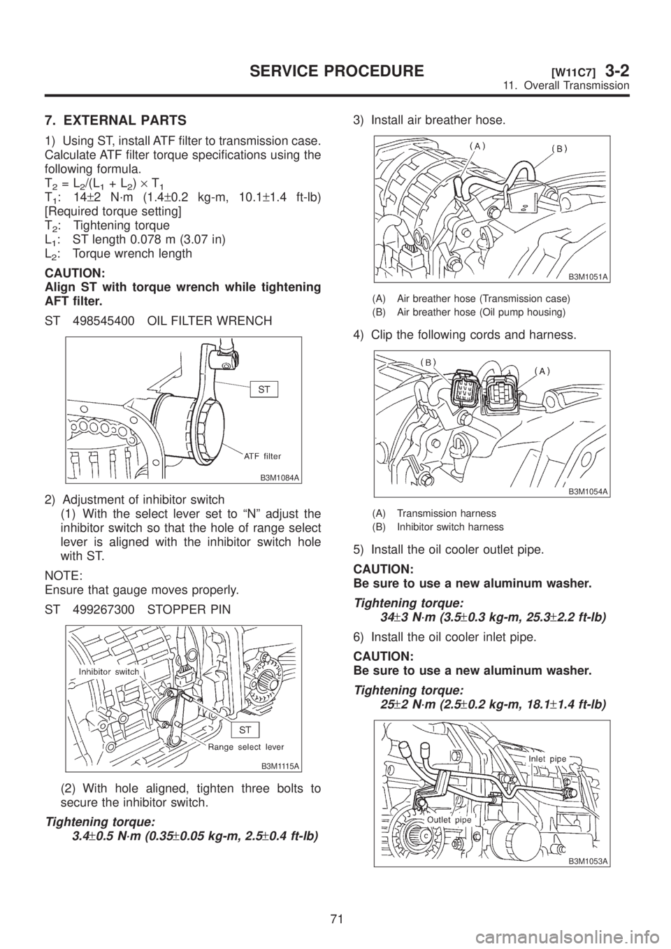
1) Using ST, install ATF filter to transmission case.
Calculate ATF filter torque specifications using the
following formula.
T
2=L2/(L1+L2)´T1T1:14±2 N´m (1.4±0.2 kg-m, 10.1±1.4 ft-lb)
[Required torque setting]
T
2: Tightening torque
L
1: ST length 0.078 m (3.07 in)
L
2: Torque wrench length
CAUTION:
Align ST with torque wrench while tightening
AFT filter.
ST 498545400 OIL FILTER WRENCH
B3M1084A
2) Adjustment of inhibitor switch
(1) With the select lever set to ªNº adjust the
inhibitor switch so that the hole of range select
lever is aligned with the inhibitor switch hole
with ST.
NOTE:
Ensure that gauge moves properly.
ST 499267300 STOPPER PIN
B3M1115A
(2) With hole aligned, tighten three bolts to
secure the inhibitor switch.
Tightening torque:
3.4
±0.5 N´m (0.35±0.05 kg-m, 2.5±0.4 ft-lb)
3) Install air breather hose.
B3M1051A
(A) Air breather hose (Transmission case)
(B) Air breather hose (Oil pump housing)
4) Clip the following cords and harness.
B3M1054A
(A) Transmission harness
(B) Inhibitor switch harness
5) Install the oil cooler outlet pipe.
CAUTION:
Be sure to use a new aluminum washer.
Tightening torque:
34
±3 N´m (3.5±0.3 kg-m, 25.3±2.2 ft-lb)
6) Install the oil cooler inlet pipe.
CAUTION:
Be sure to use a new aluminum washer.
Tightening torque:
25
±2 N´m (2.5±0.2 kg-m, 18.1±1.4 ft-lb)
B3M1053A
71
[W11C7]3-2SERVICE PROCEDURE
11. Overall Transmission
Page 605 of 1456

14. Control Valve Body
A: PRECAUTION
The control valve is composed of parts which are
accurately machined to a high degree and should
be handled carefully during disassembly and
assembly. As these parts are similar in shape, they
should be arranged in neat order on a table after
disassembly so that they can be easily installed to
their original positions. Spring loaded parts shouldbe also handled carefully, as springs may jump out
of place when the parts are disassembled or
removed. Extreme care should be taken so as not
to drop valves on the floor. Before assembling, the
parts and valves should be dipped in a container
filled with the ATF. Make sure that the valves are
clean and free from any foreign material before
assembly. Torque specifications should also be
observed.
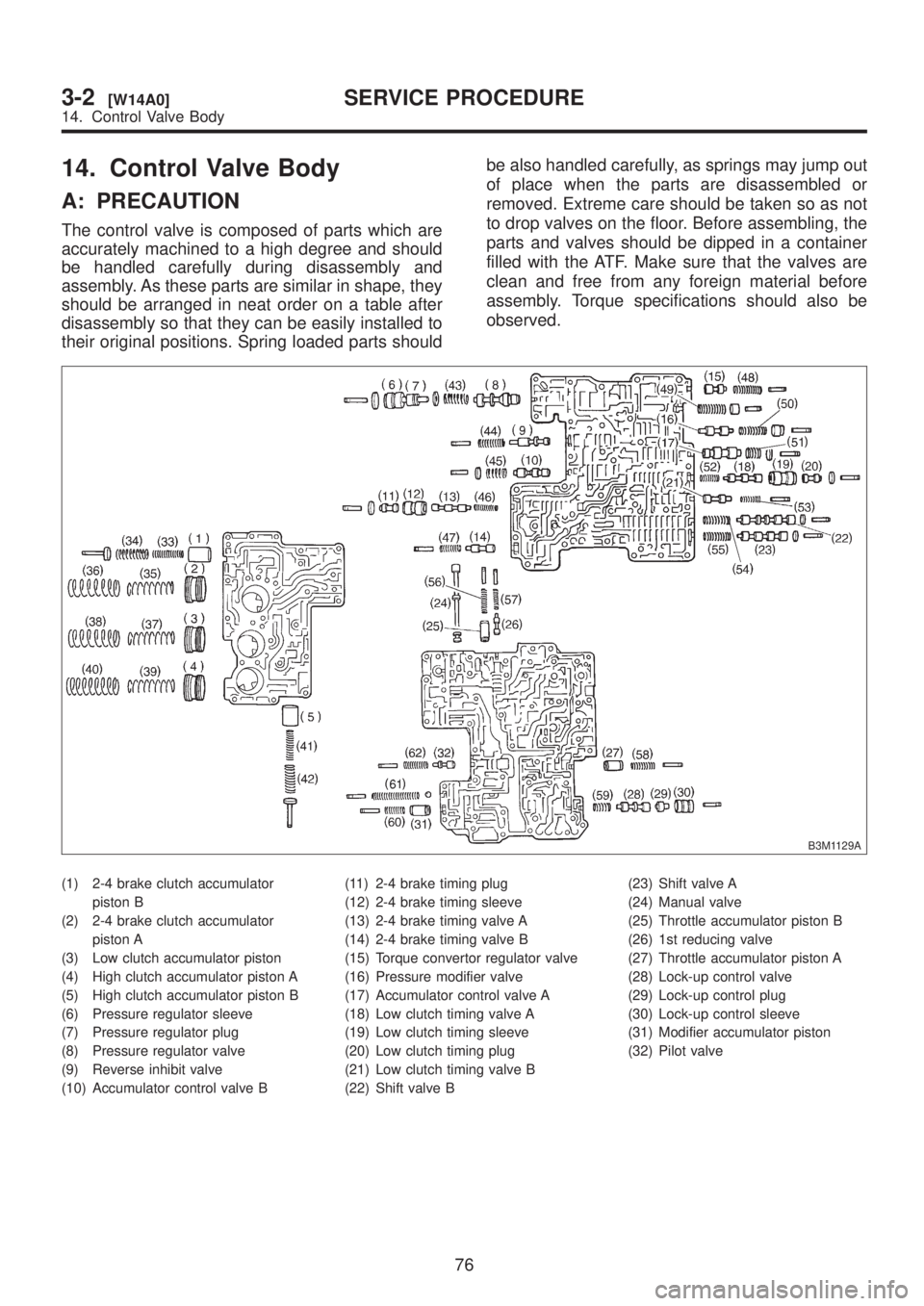
B3M1129A
(1) 2-4 brake clutch accumulator
piston B
(2) 2-4 brake clutch accumulator
piston A
(3) Low clutch accumulator piston
(4) High clutch accumulator piston A
(5) High clutch accumulator piston B
(6) Pressure regulator sleeve
(7) Pressure regulator plug
(8) Pressure regulator valve
(9) Reverse inhibit valve
(10) Accumulator control valve B(11) 2-4 brake timing plug
(12) 2-4 brake timing sleeve
(13) 2-4 brake timing valve A
(14) 2-4 brake timing valve B
(15) Torque convertor regulator valve
(16) Pressure modifier valve
(17) Accumulator control valve A
(18) Low clutch timing valve A
(19) Low clutch timing sleeve
(20) Low clutch timing plug
(21) Low clutch timing valve B
(22) Shift valve B(23) Shift valve A
(24) Manual valve
(25) Throttle accumulator piston B
(26) 1st reducing valve
(27) Throttle accumulator piston A
(28) Lock-up control valve
(29) Lock-up control plug
(30) Lock-up control sleeve
(31) Modifier accumulator piston
(32) Pilot valve
76
3-2[W14A0]SERVICE PROCEDURE
14. Control Valve Body