1999 SUBARU LEGACY specifications
[x] Cancel search: specificationsPage 876 of 1456

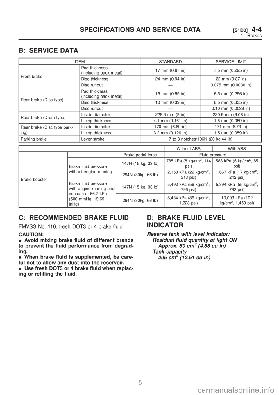
B: SERVICE DATA
ITEM STANDARD SERVICE LIMIT
Front brakePad thickness
(including back metal)17 mm (0.67 in) 7.5 mm (0.295 in)
Disc thickness 24 mm (0.94 in) 22 mm (0.87 in)
Disc runout Ð 0.075 mm (0.0030 in)
Rear brake (Disc type)Pad thickness
(including back metal)15 mm (0.59 in) 6.5 mm (0.256 in)
Disc thickness 10 mm (0.39 in) 8.5 mm (0.335 in)
Disc runout Ð 0.10 mm (0.0039 in)
Rear brake (Drum type)Inside diameter 228.6 mm (9 in) 230.6 mm (9.08 in)
Lining thickness 4.1 mm (0.161 in) 1.5 mm (0.059 in)
Rear brake (Disc type park-
ing)Inside diameter 170 mm (6.69 in) 171 mm (6.73 in)
Lining thickness 3.2 mm (0.126 in) 1.5 mm (0.059 in)
Parking brake Lever stroke 7 to 8 notches/196N (20 kg,44 lb)
Without ABS With ABS
Brake boosterBrake pedal force Fluid pressure
Brake fluid pressure
without engine running147N (15 kg, 33 lb)785 kPa (8 kg/cm
2,114
psi)588 kPa (6 kg/cm2,85
psi)
294N (30kg, 66 lb)2,158 kPa (22 kg/cm
2,
313 psi)1,667 kPa (17 kg/cm2,
242 psi)
Brake fluid pressure
with engine running and
vacuum at 66.7 kPa
(500 mmHg, 19.69
inHg)147N (15 kg, 33 lb)5,492 kPa (56 kg/cm
2,
796 psi)5,394 kPa (55 kg/cm2,
782 psi)
294N (30kg, 66 lb)8,434 kPa (86 kg/cm
2,
1,223 psi)10,003 kPa (102
kg/cm2, 1,450 psi)
C: RECOMMENDED BRAKE FLUID
FMVSS No. 116, fresh DOT3 or 4 brake fluid
CAUTION:
IAvoid mixing brake fluid of different brands
to prevent the fluid performance from degrad-
ing.
IWhen brake fluid is supplemented, be care-
ful not to allow any dust into the reservoir.
IUse fresh DOT3 or 4 brake fluid when replac-
ing or refilling the fluid.
D: BRAKE FLUID LEVEL
INDICATOR
Reserve tank with level indicator:
Residual fluid quantity at light ON
Approx. 80 cm
3(4.88 cu in)
Tank capacity
205 cm
3(12.51 cu in)
5
[S1D0]4-4SPECIFICATIONS AND SERVICE DATA
1. Brakes
Page 925 of 1456

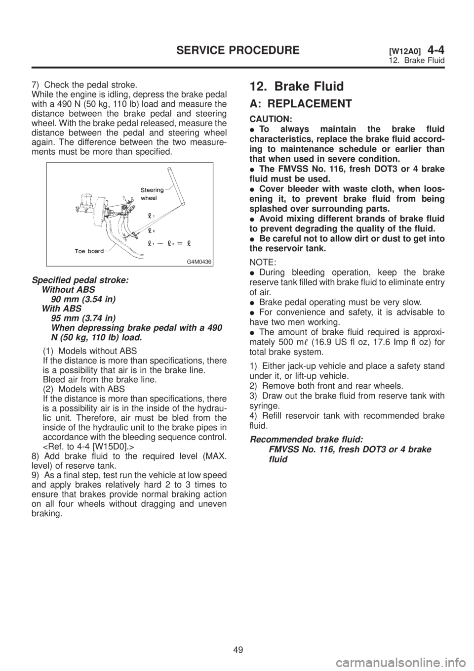
7) Check the pedal stroke.
While the engine is idling, depress the brake pedal
with a 490 N (50 kg, 110 lb) load and measure the
distance between the brake pedal and steering
wheel. With the brake pedal released, measure the
distance between the pedal and steering wheel
again. The difference between the two measure-
ments must be more than specified.
G4M0436
Specified pedal stroke:
Without ABS
90 mm (3.54 in)
With ABS
95 mm (3.74 in)
When depressing brake pedal with a 490
N (50 kg, 110 lb) load.
(1) Models without ABS
If the distance is more than specifications, there
is a possibility that air is in the brake line.
Bleed air from the brake line.
(2) Models with ABS
If the distance is more than specifications, there
is a possibility air is in the inside of the hydrau-
lic unit. Therefore, air must be bled from the
inside of the hydraulic unit to the brake pipes in
accordance with the bleeding sequence control.
8) Add brake fluid to the required level (MAX.
level) of reserve tank.
9) As a final step, test run the vehicle at low speed
and apply brakes relatively hard 2 to 3 times to
ensure that brakes provide normal braking action
on all four wheels without dragging and uneven
braking.
12. Brake Fluid
A: REPLACEMENT
CAUTION:
ITo always maintain the brake fluid
characteristics, replace the brake fluid accord-
ing to maintenance schedule or earlier than
that when used in severe condition.
IThe FMVSS No. 116, fresh DOT3 or 4 brake
fluid must be used.
ICover bleeder with waste cloth, when loos-
ening it, to prevent brake fluid from being
splashed over surrounding parts.
IAvoid mixing different brands of brake fluid
to prevent degrading the quality of the fluid.
IBe careful not to allow dirt or dust to get into
the reservoir tank.
NOTE:
IDuring bleeding operation, keep the brake
reserve tank filled with brake fluid to eliminate entry
of air.
IBrake pedal operating must be very slow.
IFor convenience and safety, it is advisable to
have two men working.
IThe amount of brake fluid required is approxi-
mately 500 m(16.9 US fl oz, 17.6 Imp fl oz) for
total brake system.
1) Either jack-up vehicle and place a safety stand
under it, or lift-up vehicle.
2) Remove both front and rear wheels.
3) Draw out the brake fluid from reserve tank with
syringe.
4) Refill reservoir tank with recommended brake
fluid.
Recommended brake fluid:
FMVSS No. 116, fresh DOT3 or 4 brake
fluid
49
[W12A0]4-4SERVICE PROCEDURE
12. Brake Fluid
Page 926 of 1456

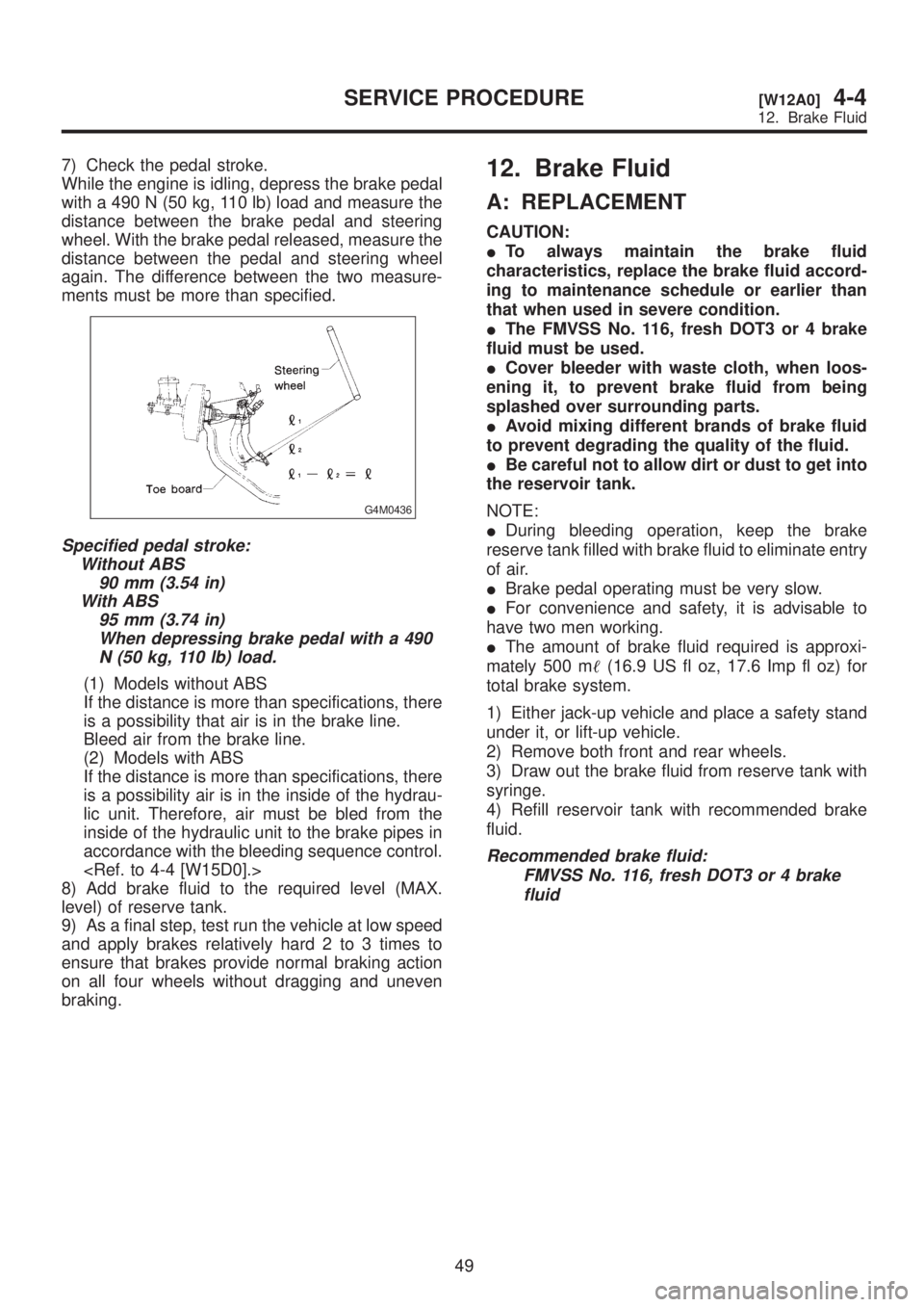
7) Check the pedal stroke.
While the engine is idling, depress the brake pedal
with a 490 N (50 kg, 110 lb) load and measure the
distance between the brake pedal and steering
wheel. With the brake pedal released, measure the
distance between the pedal and steering wheel
again. The difference between the two measure-
ments must be more than specified.
G4M0436
Specified pedal stroke:
Without ABS
90 mm (3.54 in)
With ABS
95 mm (3.74 in)
When depressing brake pedal with a 490
N (50 kg, 110 lb) load.
(1) Models without ABS
If the distance is more than specifications, there
is a possibility that air is in the brake line.
Bleed air from the brake line.
(2) Models with ABS
If the distance is more than specifications, there
is a possibility air is in the inside of the hydrau-
lic unit. Therefore, air must be bled from the
inside of the hydraulic unit to the brake pipes in
accordance with the bleeding sequence control.
8) Add brake fluid to the required level (MAX.
level) of reserve tank.
9) As a final step, test run the vehicle at low speed
and apply brakes relatively hard 2 to 3 times to
ensure that brakes provide normal braking action
on all four wheels without dragging and uneven
braking.
12. Brake Fluid
A: REPLACEMENT
CAUTION:
ITo always maintain the brake fluid
characteristics, replace the brake fluid accord-
ing to maintenance schedule or earlier than
that when used in severe condition.
IThe FMVSS No. 116, fresh DOT3 or 4 brake
fluid must be used.
ICover bleeder with waste cloth, when loos-
ening it, to prevent brake fluid from being
splashed over surrounding parts.
IAvoid mixing different brands of brake fluid
to prevent degrading the quality of the fluid.
IBe careful not to allow dirt or dust to get into
the reservoir tank.
NOTE:
IDuring bleeding operation, keep the brake
reserve tank filled with brake fluid to eliminate entry
of air.
IBrake pedal operating must be very slow.
IFor convenience and safety, it is advisable to
have two men working.
IThe amount of brake fluid required is approxi-
mately 500 m(16.9 US fl oz, 17.6 Imp fl oz) for
total brake system.
1) Either jack-up vehicle and place a safety stand
under it, or lift-up vehicle.
2) Remove both front and rear wheels.
3) Draw out the brake fluid from reserve tank with
syringe.
4) Refill reservoir tank with recommended brake
fluid.
Recommended brake fluid:
FMVSS No. 116, fresh DOT3 or 4 brake
fluid
49
[W12A0]4-4SERVICE PROCEDURE
12. Brake Fluid
Page 931 of 1456

4) Install front ABS sensor on strut and wheel
apron bracket.
Tightening torque:
32
±10 N´m (3.3±1.0 kg-m, 24±7 ft-lb)
B4M1181A
5) Place a thickness gauge between ABS sensor's
pole piece and tone wheel's tooth face. After stan-
dard clearance is obtained over the entire
perimeter, tighten ABS sensor on housing to speci-
fied torque.
ABS sensor standard clearance:
0.9 Ð 1.4 mm (0.035 Ð 0.055 in)
Tightening torque:
32
±10 N´m (3.3±1.0 kg-m, 24±7 ft-lb)
CAUTION:
Check the marks on the harness to make sure
that no distortion exists. (RH: white, LH: yel-
low)
NOTE:
If the clearance is outside specifications, readjust.
2. REAR ABS SENSOR
1) Install rear tone wheel on hub, then rear hous-
ing on hub.
2) Temporarily install rear ABS sensor on back
plate.
CAUTION:
Be careful not to strike ABS sensor's pole
piece and tone wheel's teeth against adjacent
metal parts during installation.
B4M1182A
3) Install rear drive shaft to rear housing and rear
differential spindle.
Tightening torque:
32
±10 N´m (3.3±1.0 kg-m, 24±7 ft-lb)
G4M0453
5) Place a thickness gauge between ABS sensor's
pole piece and tone wheel's tooth face. After stan-
dard clearance is obtained over the entire
perimeter, tighten ABS sensor on back plate to
specified torque.
ABS sensor standard clearance:
0.7 Ð 1.2 mm (0.028 Ð 0.047 in)
Tightening torque:
32
±10 N´m (3.3±1.0 kg-m, 24±7 ft-lb)
CAUTION:
Check the marks on the harness to make sure
that no distortion exists. (RH: white, LH: yel-
low)
NOTE:
If the clearance is outside specifications, readjust.
54
4-4[W14C2]SERVICE PROCEDURE
14. ABS Sensor
Page 933 of 1456

7) Disconnect brake pipes from ABSCM&H/U.
CAUTION:
Wrap brake pipes with vinyl bag to avoid spill-
ing brake fluid on vehicle body.
8) Remove ABSCM&H/U from engine compart-
ment.
CAUTION:
IABSCM&H/U cannot be disassembled. Do
not attempt to loosen bolts and nuts.
IDo not drop or bump ABSCM&H/U.
IDo not turn the ABSCM&H/U upside down or
place it on its side.
IBe careful to prevent foreign particles from
getting into ABSCM&H/U.
IApply a coat of rust-preventive wax (Nippeco
LT or GB) to bracket attaching bolt after tight-
ening.
IDo not pull harness disconnecting harness
connector.
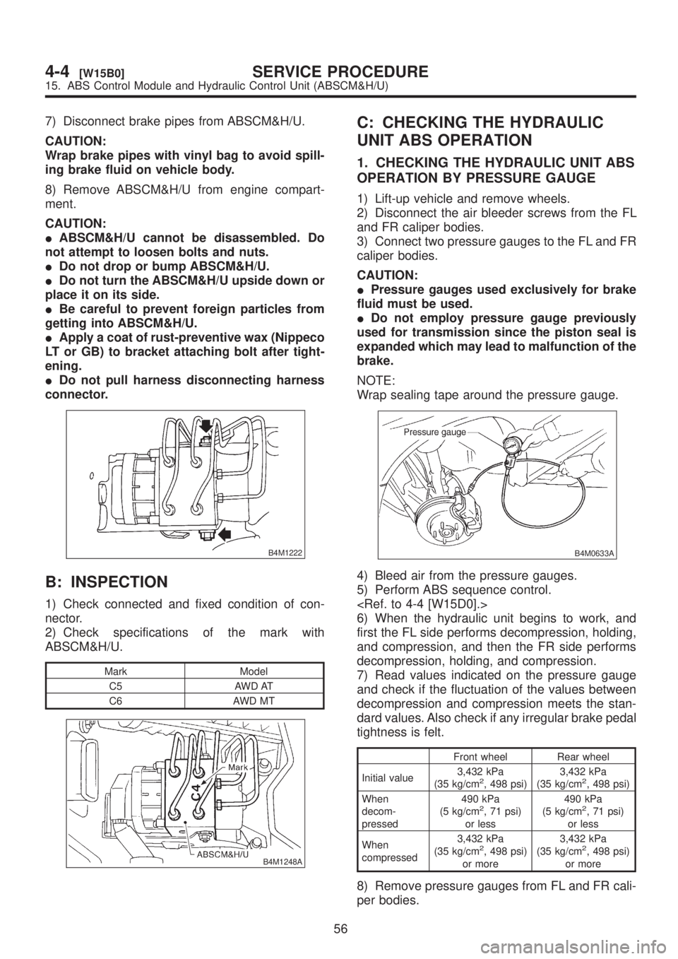
B4M1222
B: INSPECTION
1) Check connected and fixed condition of con-
nector.
2) Check specifications of the mark with
ABSCM&H/U.
Mark Model
C5 AWD AT
C6 AWD MT
B4M1248A
C: CHECKING THE HYDRAULIC
UNIT ABS OPERATION
1. CHECKING THE HYDRAULIC UNIT ABS
OPERATION BY PRESSURE GAUGE
1) Lift-up vehicle and remove wheels.
2) Disconnect the air bleeder screws from the FL
and FR caliper bodies.
3) Connect two pressure gauges to the FL and FR
caliper bodies.
CAUTION:
IPressure gauges used exclusively for brake
fluid must be used.
IDo not employ pressure gauge previously
used for transmission since the piston seal is
expanded which may lead to malfunction of the
brake.
NOTE:
Wrap sealing tape around the pressure gauge.
B4M0633A
4) Bleed air from the pressure gauges.
5) Perform ABS sequence control.
6) When the hydraulic unit begins to work, and
first the FL side performs decompression, holding,
and compression, and then the FR side performs
decompression, holding, and compression.
7) Read values indicated on the pressure gauge
and check if the fluctuation of the values between
decompression and compression meets the stan-
dard values. Also check if any irregular brake pedal
tightness is felt.
Front wheel Rear wheel
Initial value3,432 kPa
(35 kg/cm
2, 498 psi)3,432 kPa
(35 kg/cm2, 498 psi)
When
decom-
pressed490 kPa
(5 kg/cm
2, 71 psi)
or less490 kPa
(5 kg/cm2, 71 psi)
or less
When
compressed3,432 kPa
(35 kg/cm
2, 498 psi)
or more3,432 kPa
(35 kg/cm2, 498 psi)
or more
8) Remove pressure gauges from FL and FR cali-
per bodies.
56
4-4[W15B0]SERVICE PROCEDURE
15. ABS Control Module and Hydraulic Control Unit (ABSCM&H/U)
Page 937 of 1456

E: INSTALLATION
1) Install ABSCM&H/U.
CAUTION:
Confirm that the specifications of the
ABSCM&H/U conforms to the vehicle specifica-
tions.
Tightening torque:
18
±5 N´m (1.8±0.5 kg-m, 13.0±3.6 ft-lb)
B4M1222
2) Connect brake pipes to their correct
ABSCM&H/U connections.
Brake pipe tightening torque:
15+3/þ2N´m (1.5+0.3/þ0.2kg-m, 10.8+2.2/þ1.4ft-lb)
3) Using cable clip, secure ABSCM&H/U harness
to bracket.
4) Connect connector to ABSCM&H/U.
CAUTION:
IBe sure to remove all foreign matter from
inside the connector before connecting.
IEnsure that the ABSCM&H/U connetor is
securely locked.
5) Install air intake duct.
6) Connect ground cable to battery.
7) Bleed air from the brake system.
16. G Sensor
A: REMOVAL
1. FRONT ABS SENSOR
1) Disconnect front ABS sensor connector located
in engine compartment.
2) Remove bolts which secure sensor harness to
strut.
B4M1442A
3) Remove bolts which secure sensor harness to
body.
B4M1181A
4) Remove bolts which secure front ABS sensor to
housing, and remove front ABS sensor.
CAUTION:
IBe careful not to damage pole piece located
at tip of the sensor and teeth faces during
removal.
IDo not pull sensor harness during removal.
B4M1183A
5) Remove front disc brake caliper and disc rotor
from housing after removing front tire.
60
4-4[W15E0]SERVICE PROCEDURE
16. G Sensor
Page 938 of 1456

E: INSTALLATION
1) Install ABSCM&H/U.
CAUTION:
Confirm that the specifications of the
ABSCM&H/U conforms to the vehicle specifica-
tions.
Tightening torque:
18
±5 N´m (1.8±0.5 kg-m, 13.0±3.6 ft-lb)
B4M1222
2) Connect brake pipes to their correct
ABSCM&H/U connections.
Brake pipe tightening torque:
15+3/þ2N´m (1.5+0.3/þ0.2kg-m, 10.8+2.2/þ1.4ft-lb)
3) Using cable clip, secure ABSCM&H/U harness
to bracket.
4) Connect connector to ABSCM&H/U.
CAUTION:
IBe sure to remove all foreign matter from
inside the connector before connecting.
IEnsure that the ABSCM&H/U connetor is
securely locked.
5) Install air intake duct.
6) Connect ground cable to battery.
7) Bleed air from the brake system.
16. G Sensor
A: REMOVAL
1. FRONT ABS SENSOR
1) Disconnect front ABS sensor connector located
in engine compartment.
2) Remove bolts which secure sensor harness to
strut.
B4M1442A
3) Remove bolts which secure sensor harness to
body.
B4M1181A
4) Remove bolts which secure front ABS sensor to
housing, and remove front ABS sensor.
CAUTION:
IBe careful not to damage pole piece located
at tip of the sensor and teeth faces during
removal.
IDo not pull sensor harness during removal.
B4M1183A
5) Remove front disc brake caliper and disc rotor
from housing after removing front tire.
60
4-4[W15E0]SERVICE PROCEDURE
16. G Sensor
Page 941 of 1456

4) Install front ABS sensor on strut and wheel
apron bracket.
Tightening torque:
32
±10 N´m (3.3±1.0 kg-m, 24±7 ft-lb)
B4M1442A
5) Place a thickness gauge between ABS sensor's
pole piece and tone wheel's tooth face. After stan-
dard clearance is obtained over the entire
perimeter, tighten ABS sensor on housing to speci-
fied torque.
ABS sensor standard clearance:
0.9 Ð 1.4 mm (0.035 Ð 0.055 in)
Tightening torque:
32
±10 N´m (3.3±1.0 kg-m, 24±7 ft-lb)
CAUTION:
Check the marks on the harness to make sure
that no distortion exists. (RH: white, LH: yel-
low)
NOTE:
If the clearance is outside specifications, readjust.
17. Brake Pipe
A: SUPPLEMENTAL RESTRAINT
SYSTEM ªAIRBAGº
Airbag system wiring harness is routed near the
center brake pipe.
CAUTION:
IAll Airbag system wiring harness and con-
nectors are colored yellow. Do not use electri-
cal test equipment on these circuit.
IBe careful not to damage Airbag system wir-
ing harness when servicing the center brake
pipe.
B: REMOVAL AND INSTALLATION
CAUTION:
IWhen removing and installing the brake
pipe, make sure that it is not bent.
IAfter installing the brake pipe and hose,
bleed the air.
IAfter installing the brake hose, make sure
that it does not touch the tire or suspension
assembly, etc.
Brake pipe tightening torque:
15+3/þ2N´m (1.5+0.3/þ0.2kg-m, 10.8+2.2/þ1.4ft-lb)
63
[W17B0]4-4SERVICE PROCEDURE
17. Brake Pipe