1999 SUBARU LEGACY specifications
[x] Cancel search: specificationsPage 942 of 1456

4) Install front ABS sensor on strut and wheel
apron bracket.
Tightening torque:
32
±10 N´m (3.3±1.0 kg-m, 24±7 ft-lb)
B4M1442A
5) Place a thickness gauge between ABS sensor's
pole piece and tone wheel's tooth face. After stan-
dard clearance is obtained over the entire
perimeter, tighten ABS sensor on housing to speci-
fied torque.
ABS sensor standard clearance:
0.9 Ð 1.4 mm (0.035 Ð 0.055 in)
Tightening torque:
32
±10 N´m (3.3±1.0 kg-m, 24±7 ft-lb)
CAUTION:
Check the marks on the harness to make sure
that no distortion exists. (RH: white, LH: yel-
low)
NOTE:
If the clearance is outside specifications, readjust.
17. Brake Pipe
A: SUPPLEMENTAL RESTRAINT
SYSTEM ªAIRBAGº
Airbag system wiring harness is routed near the
center brake pipe.
CAUTION:
IAll Airbag system wiring harness and con-
nectors are colored yellow. Do not use electri-
cal test equipment on these circuit.
IBe careful not to damage Airbag system wir-
ing harness when servicing the center brake
pipe.
B: REMOVAL AND INSTALLATION
CAUTION:
IWhen removing and installing the brake
pipe, make sure that it is not bent.
IAfter installing the brake pipe and hose,
bleed the air.
IAfter installing the brake hose, make sure
that it does not touch the tire or suspension
assembly, etc.
Brake pipe tightening torque:
15+3/þ2N´m (1.5+0.3/þ0.2kg-m, 10.8+2.2/þ1.4ft-lb)
63
[W17B0]4-4SERVICE PROCEDURE
17. Brake Pipe
Page 944 of 1456

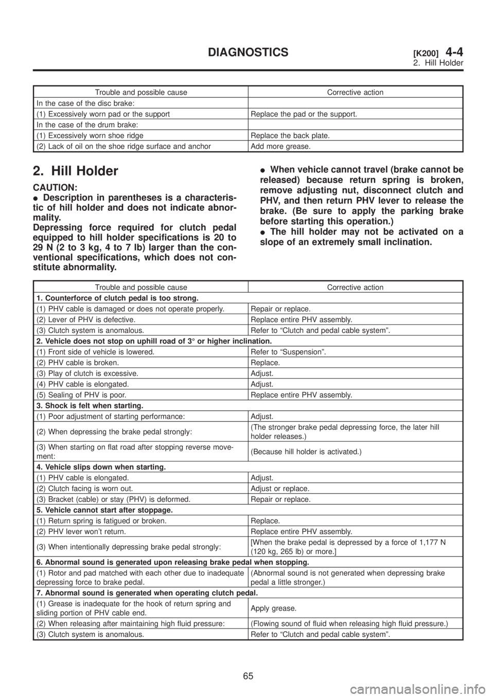
Trouble and possible cause Corrective action
In the case of the disc brake:
(1) Excessively worn pad or the support Replace the pad or the support.
In the case of the drum brake:
(1) Excessively worn shoe ridge Replace the back plate.
(2) Lack of oil on the shoe ridge surface and anchor Add more grease.
2. Hill Holder
CAUTION:
IDescription in parentheses is a characteris-
tic of hill holder and does not indicate abnor-
mality.
Depressing force required for clutch pedal
equipped to hill holder specifications is 20 to
29 N (2 to 3 kg, 4 to 7 lb) larger than the con-
ventional specifications, which does not con-
stitute abnormality.IWhen vehicle cannot travel (brake cannot be
released) because return spring is broken,
remove adjusting nut, disconnect clutch and
PHV, and then return PHV lever to release the
brake. (Be sure to apply the parking brake
before starting this operation.)
IThe hill holder may not be activated on a
slope of an extremely small inclination.
Trouble and possible cause Corrective action
1. Counterforce of clutch pedal is too strong.
(1) PHV cable is damaged or does not operate properly. Repair or replace.
(2) Lever of PHV is defective. Replace entire PHV assembly.
(3) Clutch system is anomalous. Refer to ªClutch and pedal cable systemº.
2. Vehicle does not stop on uphill road of 3É or higher inclination.
(1) Front side of vehicle is lowered. Refer to ªSuspensionº.
(2) PHV cable is broken. Replace.
(3) Play of clutch is excessive. Adjust.
(4) PHV cable is elongated. Adjust.
(5) Sealing of PHV is poor. Replace entire PHV assembly.
3. Shock is felt when starting.
(1) Poor adjustment of starting performance: Adjust.
(2) When depressing the brake pedal strongly:(The stronger brake pedal depressing force, the later hill
holder releases.)
(3) When starting on flat road after stopping reverse move-
ment:(Because hill holder is activated.)
4. Vehicle slips down when starting.
(1) PHV cable is elongated. Adjust.
(2) Clutch facing is worn out. Adjust or replace.
(3) Bracket (cable) or stay (PHV) is deformed. Repair or replace.
5. Vehicle cannot start after stoppage.
(1) Return spring is fatigued or broken. Replace.
(2) PHV lever won't return. Replace entire PHV assembly.
(3) When intentionally depressing brake pedal strongly:[When the brake pedal is depressed by a force of 1,177 N
(120 kg, 265 lb) or more.]
6. Abnormal sound is generated upon releasing brake pedal when stopping.
(1) Rotor and pad matched with each other due to inadequate
depressing force to brake pedal.(Abnormal sound is not generated when depressing brake
pedal a little stronger.)
7. Abnormal sound is generated when operating clutch pedal.
(1) Grease is inadequate for the hook of return spring and
sliding portion of PHV cable end.Apply grease.
(2) When releasing after maintaining high fluid pressure: (Flowing sound of fluid when releasing high fluid pressure.)
(3) Clutch system is anomalous. Refer to ªClutch and pedal cable systemº.
65
[K200]4-4DIAGNOSTICS
2. Hill Holder
Page 945 of 1456

Trouble and possible cause Corrective action
In the case of the disc brake:
(1) Excessively worn pad or the support Replace the pad or the support.
In the case of the drum brake:
(1) Excessively worn shoe ridge Replace the back plate.
(2) Lack of oil on the shoe ridge surface and anchor Add more grease.
2. Hill Holder
CAUTION:
IDescription in parentheses is a characteris-
tic of hill holder and does not indicate abnor-
mality.
Depressing force required for clutch pedal
equipped to hill holder specifications is 20 to
29 N (2 to 3 kg, 4 to 7 lb) larger than the con-
ventional specifications, which does not con-
stitute abnormality.IWhen vehicle cannot travel (brake cannot be
released) because return spring is broken,
remove adjusting nut, disconnect clutch and
PHV, and then return PHV lever to release the
brake. (Be sure to apply the parking brake
before starting this operation.)
IThe hill holder may not be activated on a
slope of an extremely small inclination.
Trouble and possible cause Corrective action
1. Counterforce of clutch pedal is too strong.
(1) PHV cable is damaged or does not operate properly. Repair or replace.
(2) Lever of PHV is defective. Replace entire PHV assembly.
(3) Clutch system is anomalous. Refer to ªClutch and pedal cable systemº.
2. Vehicle does not stop on uphill road of 3É or higher inclination.
(1) Front side of vehicle is lowered. Refer to ªSuspensionº.
(2) PHV cable is broken. Replace.
(3) Play of clutch is excessive. Adjust.
(4) PHV cable is elongated. Adjust.
(5) Sealing of PHV is poor. Replace entire PHV assembly.
3. Shock is felt when starting.
(1) Poor adjustment of starting performance: Adjust.
(2) When depressing the brake pedal strongly:(The stronger brake pedal depressing force, the later hill
holder releases.)
(3) When starting on flat road after stopping reverse move-
ment:(Because hill holder is activated.)
4. Vehicle slips down when starting.
(1) PHV cable is elongated. Adjust.
(2) Clutch facing is worn out. Adjust or replace.
(3) Bracket (cable) or stay (PHV) is deformed. Repair or replace.
5. Vehicle cannot start after stoppage.
(1) Return spring is fatigued or broken. Replace.
(2) PHV lever won't return. Replace entire PHV assembly.
(3) When intentionally depressing brake pedal strongly:[When the brake pedal is depressed by a force of 1,177 N
(120 kg, 265 lb) or more.]
6. Abnormal sound is generated upon releasing brake pedal when stopping.
(1) Rotor and pad matched with each other due to inadequate
depressing force to brake pedal.(Abnormal sound is not generated when depressing brake
pedal a little stronger.)
7. Abnormal sound is generated when operating clutch pedal.
(1) Grease is inadequate for the hook of return spring and
sliding portion of PHV cable end.Apply grease.
(2) When releasing after maintaining high fluid pressure: (Flowing sound of fluid when releasing high fluid pressure.)
(3) Clutch system is anomalous. Refer to ªClutch and pedal cable systemº.
65
[K200]4-4DIAGNOSTICS
2. Hill Holder
Page 947 of 1456
![SUBARU LEGACY 1999 Service Repair Manual 1. Pedal System
Brake pedal Free play1Ð3mm(0.04 Ð 0.12 in) [Depress brake pedal pad
with a force of less than 10 N (1 kg, 2 lb).]
Clutch pedalFree play At clutch pedal padExcept 2500 cc model: 10 Ð SUBARU LEGACY 1999 Service Repair Manual 1. Pedal System
Brake pedal Free play1Ð3mm(0.04 Ð 0.12 in) [Depress brake pedal pad
with a force of less than 10 N (1 kg, 2 lb).]
Clutch pedalFree play At clutch pedal padExcept 2500 cc model: 10 Ð](/manual-img/17/57435/w960_57435-946.png)
1. Pedal System
Brake pedal Free play1Ð3mm(0.04 Ð 0.12 in) [Depress brake pedal pad
with a force of less than 10 N (1 kg, 2 lb).]
Clutch pedalFree play At clutch pedal padExcept 2500 cc model: 10 Ð 20 mm (0.39 Ð 0.79 in)
2500 cc model:4Ð13mm(0.16 Ð 0.51 in)
Full stroke At clutch pedal padExcept 2500 cc model: 140 Ð 145 mm (5.51 Ð 5.71 in)
2500 cc model: 130 Ð 135 mm (5.12 Ð 5.31 in)
Accelerator pedalFree play At pedal pad1Ð4mm(0.04 Ð 0.16 in)
Stroke At pedal pad 50 Ð 55 mm (1.97 Ð 2.17 in)
2
4-5[S100]SPECIFICATIONS AND SERVICE DATA
1. Pedal System
Page 956 of 1456

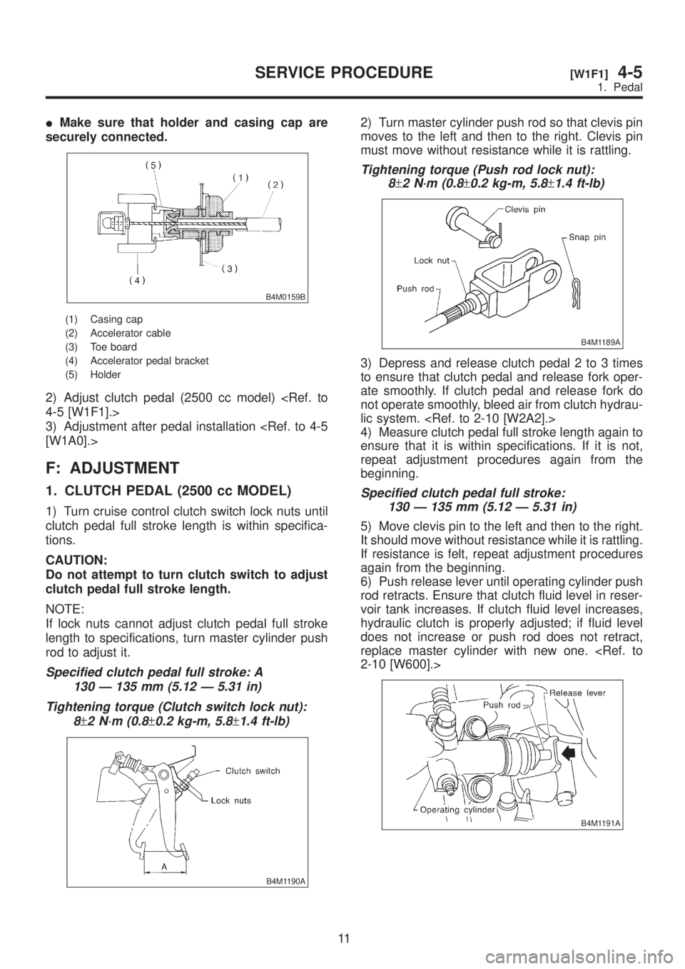
IMake sure that holder and casing cap are
securely connected.
B4M0159B
(1) Casing cap
(2) Accelerator cable
(3) Toe board
(4) Accelerator pedal bracket
(5) Holder
2) Adjust clutch pedal (2500 cc model)
3) Adjustment after pedal installation
F: ADJUSTMENT
1. CLUTCH PEDAL (2500 cc MODEL)
1) Turn cruise control clutch switch lock nuts until
clutch pedal full stroke length is within specifica-
tions.
CAUTION:
Do not attempt to turn clutch switch to adjust
clutch pedal full stroke length.
NOTE:
If lock nuts cannot adjust clutch pedal full stroke
length to specifications, turn master cylinder push
rod to adjust it.
Specified clutch pedal full stroke: A
130 Ð 135 mm (5.12 Ð 5.31 in)
Tightening torque (Clutch switch lock nut):
8
±2 N´m (0.8±0.2 kg-m, 5.8±1.4 ft-lb)
B4M1190A
2) Turn master cylinder push rod so that clevis pin
moves to the left and then to the right. Clevis pin
must move without resistance while it is rattling.
Tightening torque (Push rod lock nut):
8
±2 N´m (0.8±0.2 kg-m, 5.8±1.4 ft-lb)
B4M1189A
3) Depress and release clutch pedal 2 to 3 times
to ensure that clutch pedal and release fork oper-
ate smoothly. If clutch pedal and release fork do
not operate smoothly, bleed air from clutch hydrau-
lic system.
4) Measure clutch pedal full stroke length again to
ensure that it is within specifications. If it is not,
repeat adjustment procedures again from the
beginning.
Specified clutch pedal full stroke:
130 Ð 135 mm (5.12 Ð 5.31 in)
5) Move clevis pin to the left and then to the right.
It should move without resistance while it is rattling.
If resistance is felt, repeat adjustment procedures
again from the beginning.
6) Push release lever until operating cylinder push
rod retracts. Ensure that clutch fluid level in reser-
voir tank increases. If clutch fluid level increases,
hydraulic clutch is properly adjusted; if fluid level
does not increase or push rod does not retract,
replace master cylinder with new one.
B4M1191A
11
[W1F1]4-5SERVICE PROCEDURE
1. Pedal
Page 962 of 1456

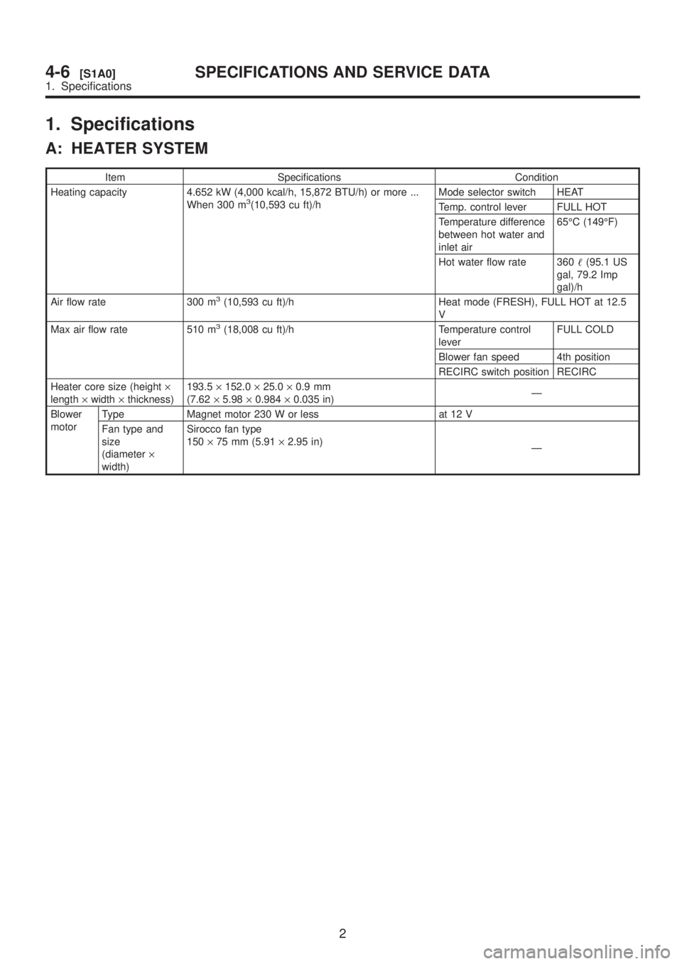
1. Specifications
A: HEATER SYSTEM
Item Specifications Condition
Heating capacity 4.652 kW (4,000 kcal/h, 15,872 BTU/h) or more ...
When 300 m
3(10,593 cu ft)/hMode selector switch HEAT
Temp. control lever FULL HOT
Temperature difference
between hot water and
inlet air65ÉC (149ÉF)
Hot water flow rate 360(95.1 US
gal, 79.2 Imp
gal)/h
Air flow rate 300 m
3(10,593 cu ft)/h Heat mode (FRESH), FULL HOT at 12.5
V
Max air flow rate 510 m
3(18,008 cu ft)/h Temperature control
leverFULL COLD
Blower fan speed 4th position
RECIRC switch position RECIRC
Heater core size (height´
length´width´thickness)193.5´152.0´25.0´0.9 mm
(7.62´5.98´0.984´0.035 in)Ð
Blower
motorType Magnet motor 230 W or less at 12 V
Fan type and
size
(diameter´
width)Sirocco fan type
150´75 mm (5.91´2.95 in)
Ð
2
4-6[S1A0]SPECIFICATIONS AND SERVICE DATA
1. Specifications
Page 976 of 1456

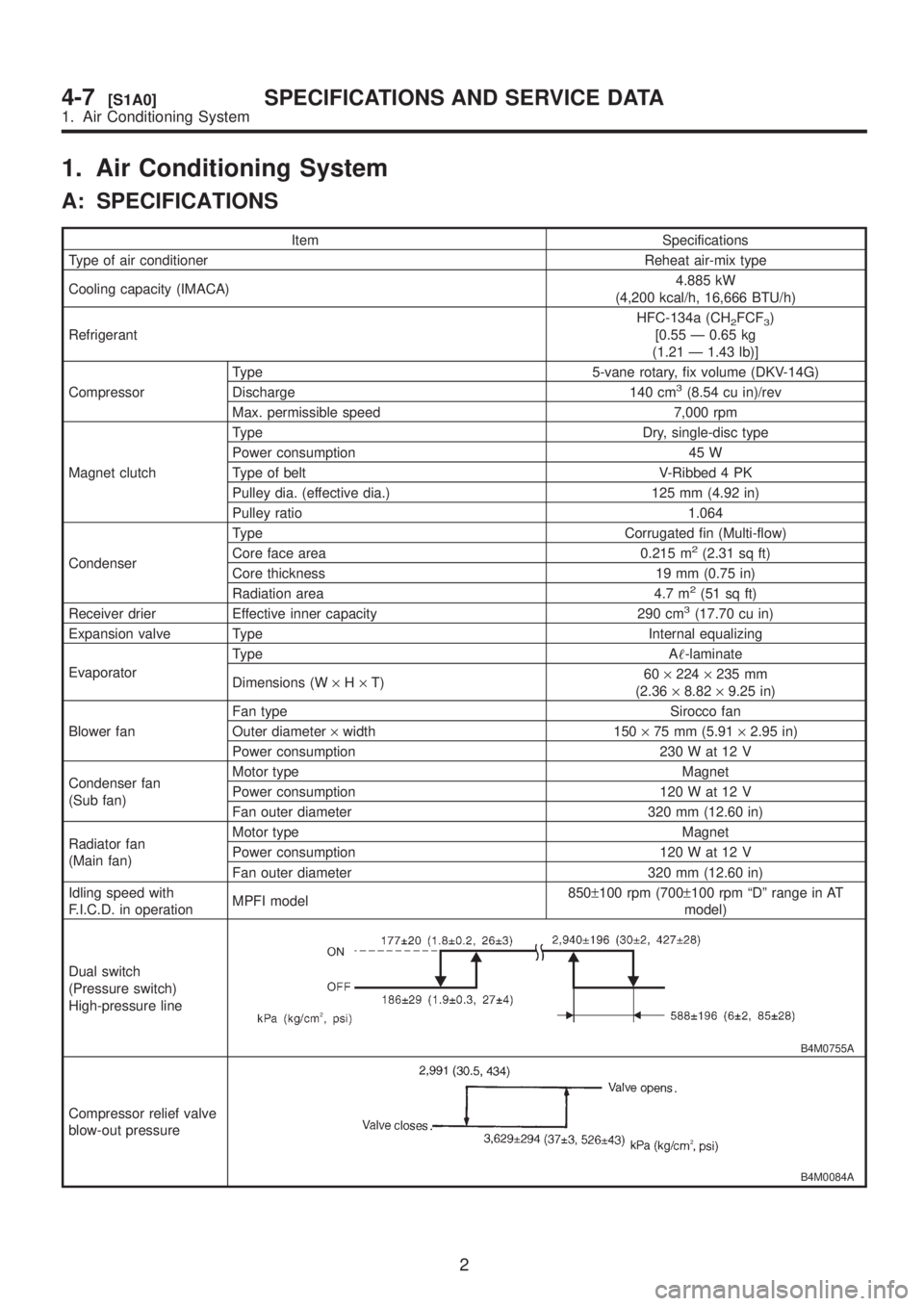
1. Air Conditioning System
A: SPECIFICATIONS
Item Specifications
Type of air conditioner Reheat air-mix type
Cooling capacity (IMACA)4.885 kW
(4,200 kcal/h, 16,666 BTU/h)
RefrigerantHFC-134a (CH
2FCF3)
[0.55 Ð 0.65 kg
(1.21 Ð 1.43 lb)]
CompressorType 5-vane rotary, fix volume (DKV-14G)
Discharge 140 cm
3(8.54 cu in)/rev
Max. permissible speed 7,000 rpm
Magnet clutchType Dry, single-disc type
Power consumption 45 W
Type of belt V-Ribbed 4 PK
Pulley dia. (effective dia.) 125 mm (4.92 in)
Pulley ratio 1.064
CondenserType Corrugated fin (Multi-flow)
Core face area 0.215 m
2(2.31 sq ft)
Core thickness 19 mm (0.75 in)
Radiation area 4.7 m
2(51 sq ft)
Receiver drier Effective inner capacity 290 cm3(17.70 cu in)
Expansion valve Type Internal equalizing
EvaporatorType A-laminate
Dimensions (W´H´T)60´224´235 mm
(2.36´8.82´9.25 in)
Blower fanFan type Sirocco fan
Outer diameter´width 150´75 mm (5.91´2.95 in)
Power consumption 230 W at 12 V
Condenser fan
(Sub fan)Motor type Magnet
Power consumption 120 W at 12 V
Fan outer diameter 320 mm (12.60 in)
Radiator fan
(Main fan)Motor type Magnet
Power consumption 120 W at 12 V
Fan outer diameter 320 mm (12.60 in)
Idling speed with
F.I.C.D. in operationMPFI model850±100 rpm (700±100 rpm ªDº range in AT
model)
Dual switch
(Pressure switch)
High-pressure line
B4M0755A
Compressor relief valve
blow-out pressure
B4M0084A
2
4-7[S1A0]SPECIFICATIONS AND SERVICE DATA
1. Air Conditioning System
Page 977 of 1456
![SUBARU LEGACY 1999 Service Repair Manual Item Specifications
Thermo control amplifier
working temperature
(Evaporator outlet air)
B4M0756B
3
[S1A0]4-7SPECIFICATIONS AND SERVICE DATA
1. Air Conditioning System SUBARU LEGACY 1999 Service Repair Manual Item Specifications
Thermo control amplifier
working temperature
(Evaporator outlet air)
B4M0756B
3
[S1A0]4-7SPECIFICATIONS AND SERVICE DATA
1. Air Conditioning System](/manual-img/17/57435/w960_57435-976.png)
Item Specifications
Thermo control amplifier
working temperature
(Evaporator outlet air)
B4M0756B
3
[S1A0]4-7SPECIFICATIONS AND SERVICE DATA
1. Air Conditioning System