Page 1048 of 1456
4. Datum Points and Dimensions Concerning On-Board Aiming
Adjustment
If headlight aiming is misaligned due to damaged body panel, repair headlight mating surface using body
and headlight datum points as a guide.
NOTE:
It is recommended to conduct On-Board Aiming Adjustment with headlights turned off.
If turned on during the adjustment, the duration should be within two minutes.
B5M0364A
Point to point Dimension Point to point Dimension
(0) to (A) LH 1,015 (39.96) (0) to (B) LH 1,057 (41.61)
(0) to (A) RH 1,015 (39.96) (0) to (B) RH 1,057 (41.61)
Unit: mm (in)
25
[S400]5-1SPECIFICATIONS AND SERVICE DATA
4. Datum Points and Dimensions Concerning On-Board Aiming Adjustment
Page 1088 of 1456
![SUBARU LEGACY 1999 Service Repair Manual 4) Tilt up assembly:
(1) Remove sunroof flame. <Ref. to 5-1
[W16A2].>
(2) Remove tilt up assembly.
B5M0485A
(3) Installation is in the reverse order of
removal.
B: ADJUSTMENT
1. SEDAN AND WAGON REAR ( SUBARU LEGACY 1999 Service Repair Manual 4) Tilt up assembly:
(1) Remove sunroof flame. <Ref. to 5-1
[W16A2].>
(2) Remove tilt up assembly.
B5M0485A
(3) Installation is in the reverse order of
removal.
B: ADJUSTMENT
1. SEDAN AND WAGON REAR (](/manual-img/17/57435/w960_57435-1087.png)
4) Tilt up assembly:
(1) Remove sunroof flame.
[W16A2].>
(2) Remove tilt up assembly.
B5M0485A
(3) Installation is in the reverse order of
removal.
B: ADJUSTMENT
1. SEDAN AND WAGON REAR (EXCEPT
OUTBACK)
1) Alignment of height between glass lid assembly
and roof panel:
(1) Remove guide rail cover.
(2) Loosen nuts and adjust height by adding
(Max: two pieces) and extracting (Max: one
piece) shim(s) (Standard: one piece) between
glass lid assembly and lid bracket.
Difference in height between glass lid assem-
bly and roof panel:
0
±0.5 mm (0±0.020 in)
B5M0314B
B5M0315B
2) Alignment of glass lid assembly with roof panel:
(1) Remove guide rail cover.
(2) Loosen nuts and move glass lid assembly
to either side to adjust front, rear, right, and left
side partitions.
Partition clearance:
7.0
±0.5 mm (0.276±0.020 in)
B5M0316A
3) Checking for movement of glass lid assembly
itself:
(1) Before installing sunroof motor, check glass
lid assembly for movement.
(2) Place a cloth on glass lid assembly and sun
shade, and attach a spring scale to glass lid
assembly edge using the cloth.
B5M0317
(3) Pull spring scale to measure force required
to move glass lid assembly.
Force required to move glass lid assembly
and sun shade trim:
Less than 196 N (20 kg, 44 lb)
Considerable effort is required to start glass lid
assembly moving, so take scale reading while
glass lid assembly is moving smoothly.
(4) If force required exceeds specifications,
check the following points:
IGlass lid assembly, sun shade and deflector and
guide rail assembly for improper installation
ICable for seizure
60
5-1[W16B1]SERVICE PROCEDURE
16. Sunroof
Page 1101 of 1456
1. Door Alignment
B5M0051A
2
5-2[S100]SPECIFICATIONS AND SERVICE DATA
1. Door Alignment
Page 1122 of 1456
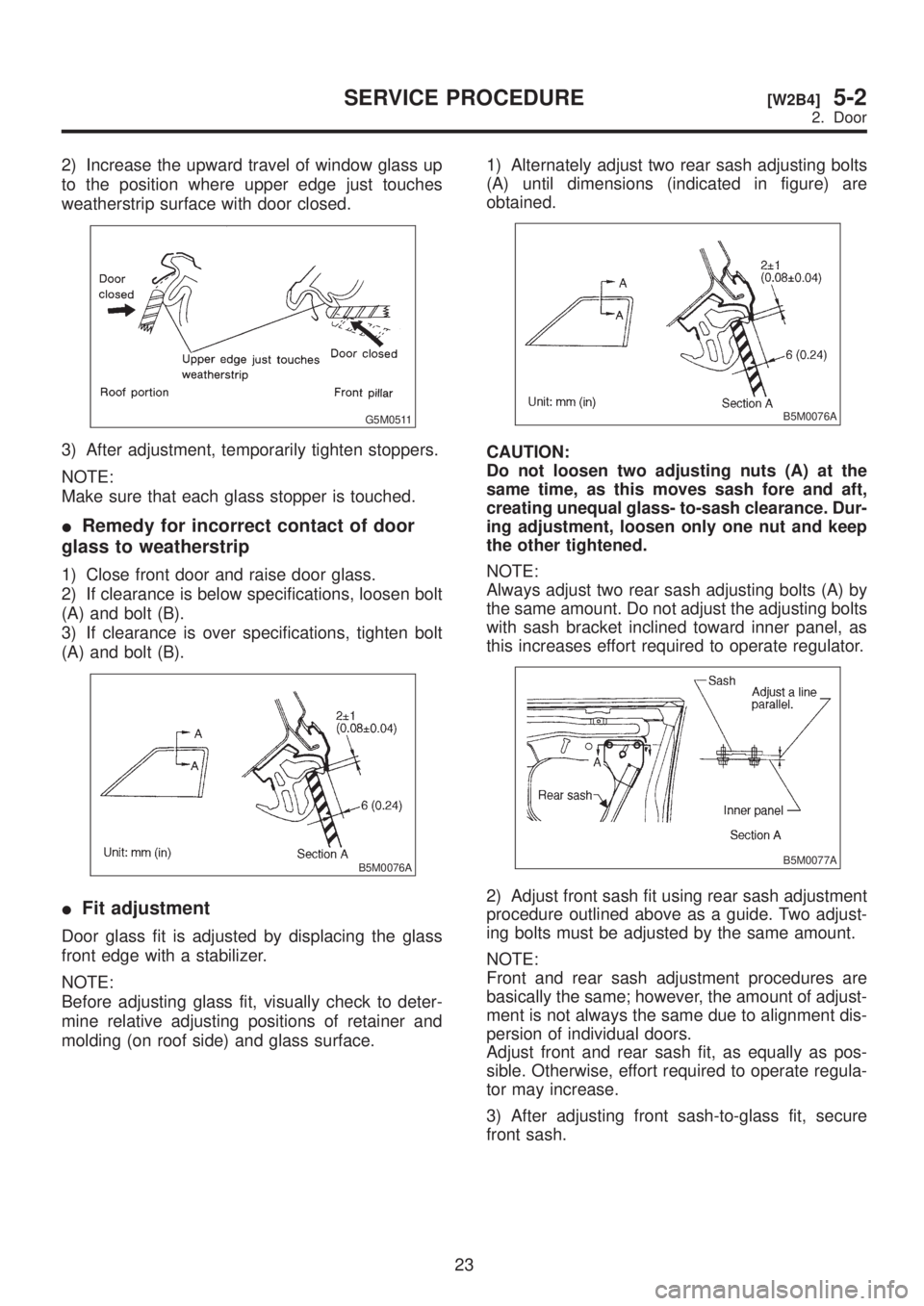
2) Increase the upward travel of window glass up
to the position where upper edge just touches
weatherstrip surface with door closed.
G5M0511
3) After adjustment, temporarily tighten stoppers.
NOTE:
Make sure that each glass stopper is touched.
IRemedy for incorrect contact of door
glass to weatherstrip
1) Close front door and raise door glass.
2) If clearance is below specifications, loosen bolt
(A) and bolt (B).
3) If clearance is over specifications, tighten bolt
(A) and bolt (B).
B5M0076A
IFit adjustment
Door glass fit is adjusted by displacing the glass
front edge with a stabilizer.
NOTE:
Before adjusting glass fit, visually check to deter-
mine relative adjusting positions of retainer and
molding (on roof side) and glass surface.1) Alternately adjust two rear sash adjusting bolts
(A) until dimensions (indicated in figure) are
obtained.
B5M0076A
CAUTION:
Do not loosen two adjusting nuts (A) at the
same time, as this moves sash fore and aft,
creating unequal glass- to-sash clearance. Dur-
ing adjustment, loosen only one nut and keep
the other tightened.
NOTE:
Always adjust two rear sash adjusting bolts (A) by
the same amount. Do not adjust the adjusting bolts
with sash bracket inclined toward inner panel, as
this increases effort required to operate regulator.
B5M0077A
2) Adjust front sash fit using rear sash adjustment
procedure outlined above as a guide. Two adjust-
ing bolts must be adjusted by the same amount.
NOTE:
Front and rear sash adjustment procedures are
basically the same; however, the amount of adjust-
ment is not always the same due to alignment dis-
persion of individual doors.
Adjust front and rear sash fit, as equally as pos-
sible. Otherwise, effort required to operate regula-
tor may increase.
3) After adjusting front sash-to-glass fit, secure
front sash.
23
[W2B4]5-2SERVICE PROCEDURE
2. Door
Page 1169 of 1456
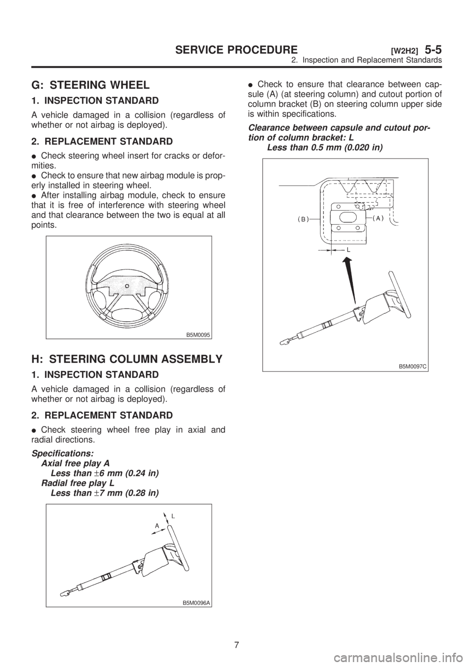
G: STEERING WHEEL
1. INSPECTION STANDARD
A vehicle damaged in a collision (regardless of
whether or not airbag is deployed).
2. REPLACEMENT STANDARD
ICheck steering wheel insert for cracks or defor-
mities.
ICheck to ensure that new airbag module is prop-
erly installed in steering wheel.
IAfter installing airbag module, check to ensure
that it is free of interference with steering wheel
and that clearance between the two is equal at all
points.
B5M0095
H: STEERING COLUMN ASSEMBLY
1. INSPECTION STANDARD
A vehicle damaged in a collision (regardless of
whether or not airbag is deployed).
2. REPLACEMENT STANDARD
ICheck steering wheel free play in axial and
radial directions.
Specifications:
Axial free play A
Less than
±6 mm (0.24 in)
Radial free play L
Less than
±7 mm (0.28 in)
B5M0096A
ICheck to ensure that clearance between cap-
sule (A) (at steering column) and cutout portion of
column bracket (B) on steering column upper side
is within specifications.
Clearance between capsule and cutout por-
tion of column bracket: L
Less than 0.5 mm (0.020 in)
B5M0097C
7
[W2H2]5-5SERVICE PROCEDURE
2. Inspection and Replacement Standards
Page 1183 of 1456
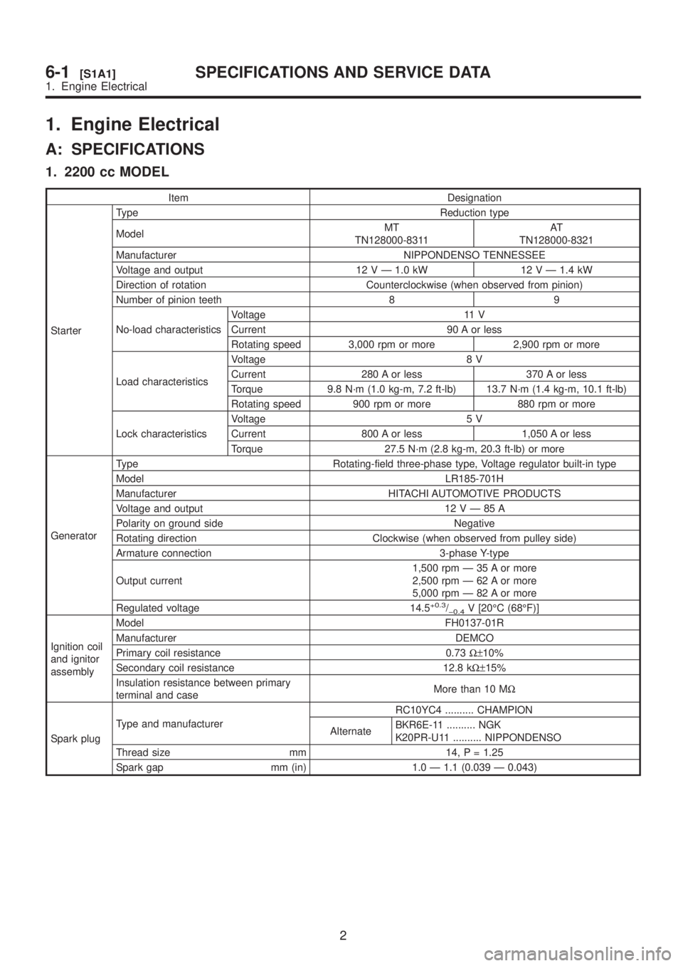
1. Engine Electrical
A: SPECIFICATIONS
1. 2200 cc MODEL
Item Designation
StarterType Reduction type
ModelMT
TN128000-8311AT
TN128000-8321
Manufacturer NIPPONDENSO TENNESSEE
Voltage and output 12 V Ð 1.0 kW 12 V Ð 1.4 kW
Direction of rotation Counterclockwise (when observed from pinion)
Number of pinion teeth 8 9
No-load characteristicsVoltage 11 V
Current 90 A or less
Rotating speed 3,000 rpm or more 2,900 rpm or more
Load characteristicsVoltage 8 V
Current 280 A or less 370 A or less
Torque 9.8 N´m (1.0 kg-m, 7.2 ft-lb) 13.7 N´m (1.4 kg-m, 10.1 ft-lb)
Rotating speed 900 rpm or more 880 rpm or more
Lock characteristicsVoltage 5 V
Current 800 A or less 1,050 A or less
Torque 27.5 N´m (2.8 kg-m, 20.3 ft-lb) or more
GeneratorType Rotating-field three-phase type, Voltage regulator built-in type
Model LR185-701H
Manufacturer HITACHI AUTOMOTIVE PRODUCTS
Voltage and output 12VÐ85A
Polarity on ground side Negative
Rotating direction Clockwise (when observed from pulley side)
Armature connection 3-phase Y-type
Output current1,500 rpm Ð 35 A or more
2,500 rpm Ð 62 A or more
5,000 rpm Ð 82 A or more
Regulated voltage 14.5
+0.3/þ0.4V [20ÉC (68ÉF)]
Ignition coil
and ignitor
assemblyModel FH0137-01R
Manufacturer DEMCO
Primary coil resistance 0.73W±10%
Secondary coil resistance 12.8 kW±15%
Insulation resistance between primary
terminal and caseMore than 10 MW
Spark plugType and manufacturerRC10YC4 .......... CHAMPION
AlternateBKR6E-11 .......... NGK
K20PR-U11 .......... NIPPONDENSO
Thread size mm 14, P = 1.25
Spark gap mm (in) 1.0 Ð 1.1 (0.039 Ð 0.043)
2
6-1[S1A1]SPECIFICATIONS AND SERVICE DATA
1. Engine Electrical
Page 1184 of 1456
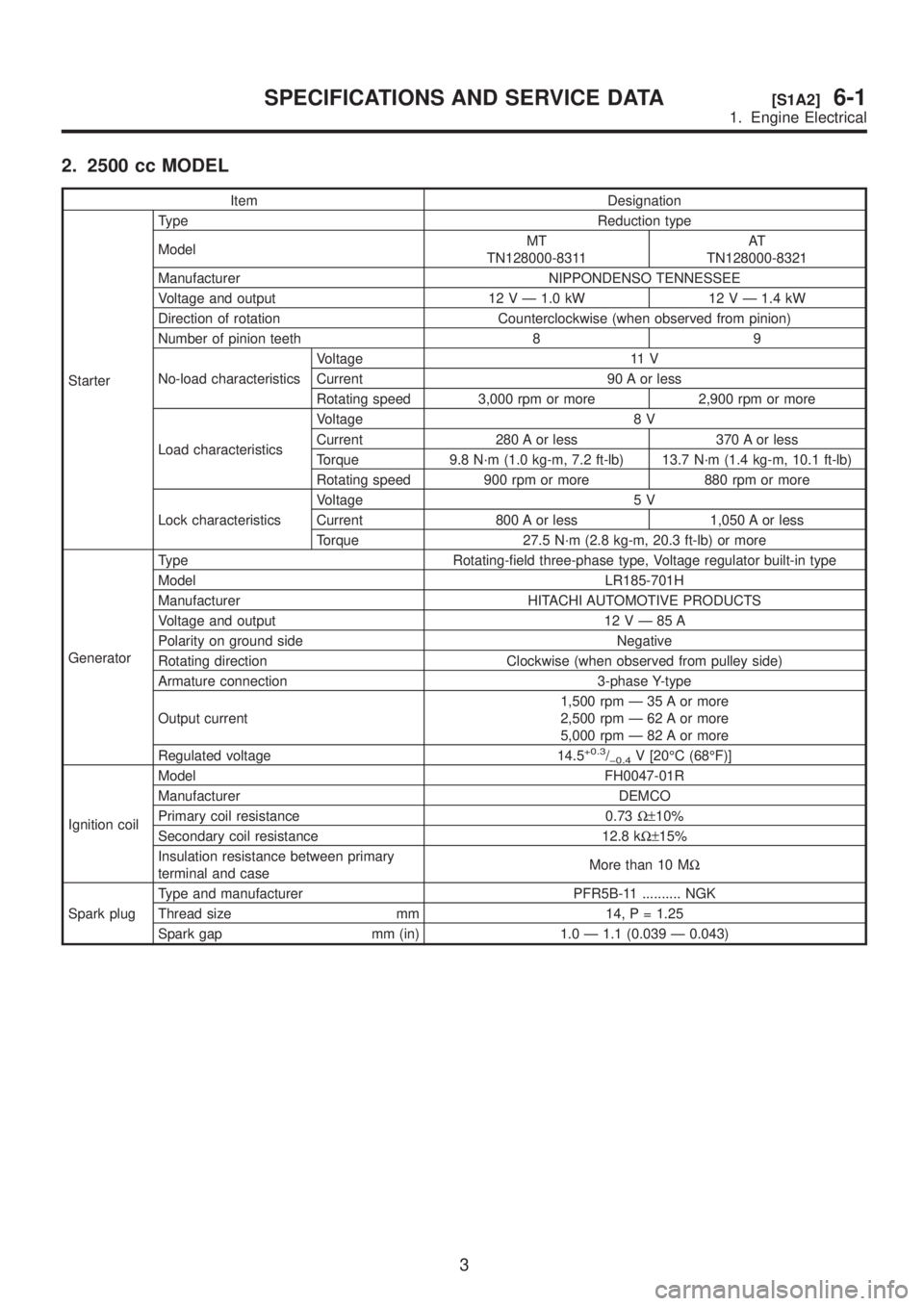
2. 2500 cc MODEL
Item Designation
StarterType Reduction type
ModelMT
TN128000-8311AT
TN128000-8321
Manufacturer NIPPONDENSO TENNESSEE
Voltage and output 12 V Ð 1.0 kW 12 V Ð 1.4 kW
Direction of rotation Counterclockwise (when observed from pinion)
Number of pinion teeth 8 9
No-load characteristicsVoltage 11 V
Current 90 A or less
Rotating speed 3,000 rpm or more 2,900 rpm or more
Load characteristicsVoltage 8 V
Current 280 A or less 370 A or less
Torque 9.8 N´m (1.0 kg-m, 7.2 ft-lb) 13.7 N´m (1.4 kg-m, 10.1 ft-lb)
Rotating speed 900 rpm or more 880 rpm or more
Lock characteristicsVoltage 5 V
Current 800 A or less 1,050 A or less
Torque 27.5 N´m (2.8 kg-m, 20.3 ft-lb) or more
GeneratorType Rotating-field three-phase type, Voltage regulator built-in type
Model LR185-701H
Manufacturer HITACHI AUTOMOTIVE PRODUCTS
Voltage and output 12VÐ85A
Polarity on ground side Negative
Rotating direction Clockwise (when observed from pulley side)
Armature connection 3-phase Y-type
Output current1,500 rpm Ð 35 A or more
2,500 rpm Ð 62 A or more
5,000 rpm Ð 82 A or more
Regulated voltage 14.5
+0.3/þ0.4V [20ÉC (68ÉF)]
Ignition coilModel FH0047-01R
Manufacturer DEMCO
Primary coil resistance 0.73W±10%
Secondary coil resistance 12.8 kW±15%
Insulation resistance between primary
terminal and caseMore than 10 MW
Spark plugType and manufacturer PFR5B-11 .......... NGK
Thread size mm 14, P = 1.25
Spark gap mm (in) 1.0 Ð 1.1 (0.039 Ð 0.043)
3
[S1A2]6-1SPECIFICATIONS AND SERVICE DATA
1. Engine Electrical
Page 1226 of 1456
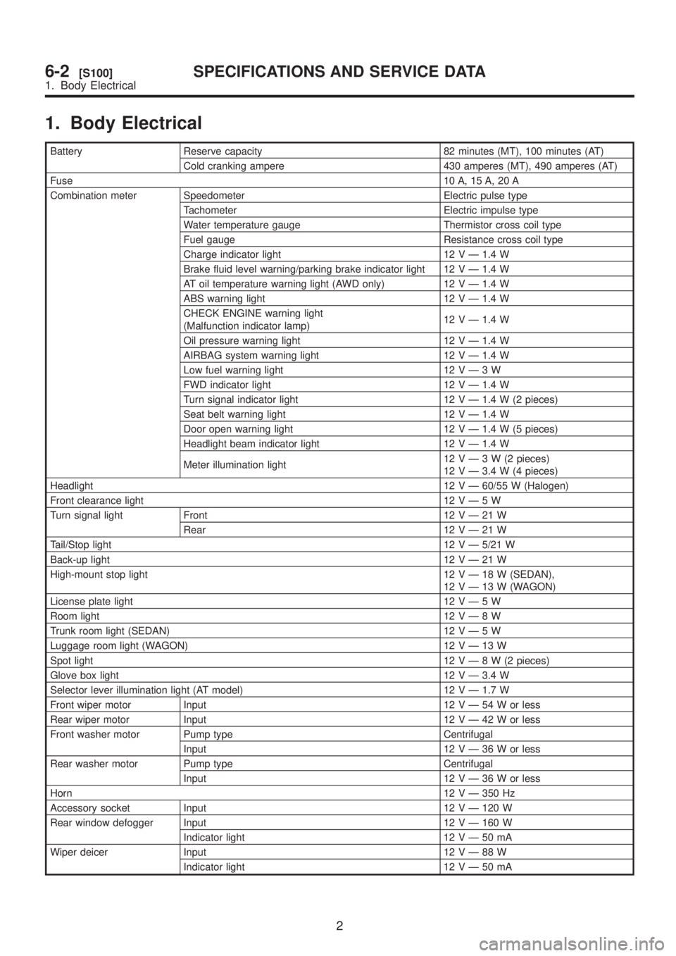
1. Body Electrical
Battery Reserve capacity 82 minutes (MT), 100 minutes (AT)
Cold cranking ampere 430 amperes (MT), 490 amperes (AT)
Fuse10 A, 15 A, 20 A
Combination meter Speedometer Electric pulse type
Tachometer Electric impulse type
Water temperature gauge Thermistor cross coil type
Fuel gauge Resistance cross coil type
Charge indicator light 12 V Ð 1.4 W
Brake fluid level warning/parking brake indicator light 12 V Ð 1.4 W
AT oil temperature warning light (AWD only) 12 V Ð 1.4 W
ABS warning light 12 V Ð 1.4 W
CHECK ENGINE warning light
(Malfunction indicator lamp)12 V Ð 1.4 W
Oil pressure warning light 12 V Ð 1.4 W
AIRBAG system warning light 12 V Ð 1.4 W
Low fuel warning light 12VÐ3W
FWD indicator light 12 V Ð 1.4 W
Turn signal indicator light 12 V Ð 1.4 W (2 pieces)
Seat belt warning light 12 V Ð 1.4 W
Door open warning light 12 V Ð 1.4 W (5 pieces)
Headlight beam indicator light 12 V Ð 1.4 W
Meter illumination light12VÐ3W(2pieces)
12 V Ð 3.4 W (4 pieces)
Headlight12 V Ð 60/55 W (Halogen)
Front clearance light 12VÐ5W
Turn signal light Front 12VÐ21W
Rear 12VÐ21W
Tail/Stop light12 V Ð 5/21 W
Back-up light12VÐ21W
High-mount stop light 12VÐ18W(SEDAN),
12VÐ13W(WAGON)
License plate light 12VÐ5W
Room light12VÐ8W
Trunk room light (SEDAN) 12VÐ5W
Luggage room light (WAGON) 12VÐ13W
Spot light12VÐ8W(2pieces)
Glove box light 12 V Ð 3.4 W
Selector lever illumination light (AT model) 12 V Ð 1.7 W
Front wiper motor Input 12VÐ54Worless
Rear wiper motor Input 12VÐ42Worless
Front washer motor Pump type Centrifugal
Input 12VÐ36Worless
Rear washer motor Pump type Centrifugal
Input 12VÐ36Worless
Horn12 V Ð 350 Hz
Accessory socket Input 12 V Ð 120 W
Rear window defogger Input 12 V Ð 160 W
Indicator light 12VÐ50mA
Wiper deicer Input 12VÐ88W
Indicator light 12VÐ50mA
2
6-2[S100]SPECIFICATIONS AND SERVICE DATA
1. Body Electrical