Page 35 of 1456

3. Engine Idle Speed
A: MEASUREMENT
1) Before checking idle speed, check the follow-
ing:
(1) Ensure that air cleaner element is free from
clogging, ignition timing is correct, spark plugs
are in good condition, and that hoses are con-
nected properly.
(2) Ensure that malfunction indicator light
(CHECK ENGINE light) does not illuminate.
2) Warm-up the engine.
3) Stop the engine, and turn ignition switch to
OFF.
4) When using SUBARU SELECT MONITOR;
NOTE:
For detailed operation procedures, refer to the
SUBARU SELECT MONITOR OPERATION
MANUAL.
(1) Insert the cartridge to SUBARU SELECT
MONITOR.
ST 24082AA090 CARTRIDGE
S2M0286A
(2) Connect SUBARU SELECT MONITOR to
the data link connector.
(3) Turn ignition switch to ON, and SUBARU
SELECT MONITOR switch to ON.
(4) Select {2. Each System Check} in Main
Menu.
(5) Select {EGI/EMPI} in Selection Menu.
(6) Select {1. Current Data Display & Save} in
EGI/EMPI Diagnosis.
(7) Select {1.12 Data Display} in Data Display
Menu.(8) Start the engine, and read engine idle
speed.
S2M0098
5) When using tachometer (Secondary pick-up
type).
(1) Attach the pick-up clip to No. 1 cylinder
spark plug cord.
(2) Start the engine, and read engine idle
speed.
B2M2011
NOTE:
IWhen using the OBD-II general scan tool, care-
fully read its operation manual.
IThis ignition system provides simultaneous igni-
tion for #1 and #2 plugs. It must be noted that
some tachometers may register twice that of actual
engine speed.
6) Check idle speed when unloaded. (With
headlights, heater fan, rear defroster, radiator fan,
air conditioning, etc. OFF)
Idle speed (No load and gears in neutral (MT),
or N or P (AT) position):
700
±100 rpm
7) Check idle speed when loaded. (Turn air con-
ditioning switch to |P¢rdquo;ON|P'ldquo; and oper-
ate compressor for at least one minute before
measurement.)
Idle speed [A/C ªONº, no load and gears in
neutral (MT) or N or P (AT) position]:
850
±50 rpm
3
[W3A0]2-2SERVICE PROCEDURE
3. Engine Idle Speed
Page 107 of 1456

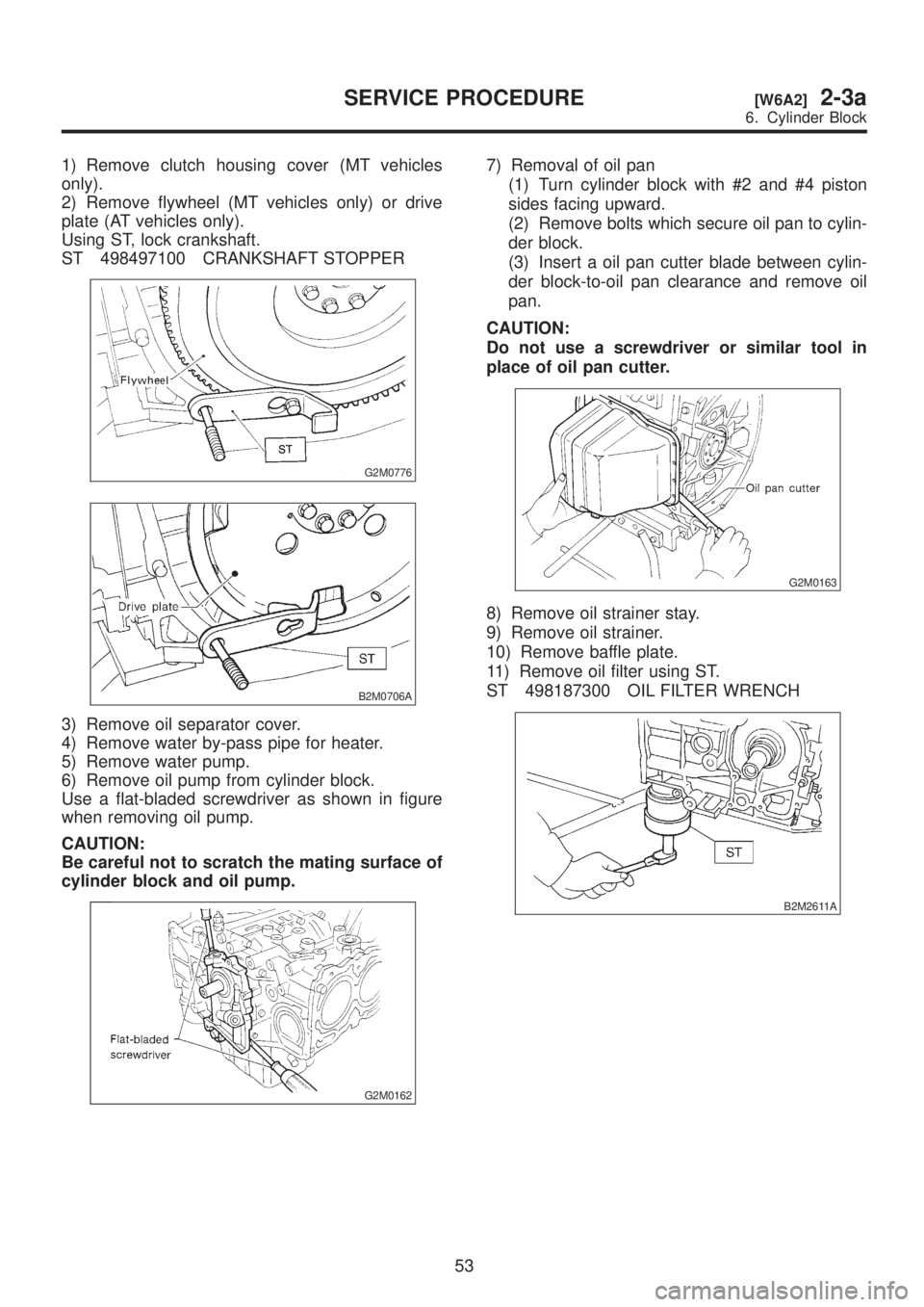
1) Remove clutch housing cover (MT vehicles
only).
2) Remove flywheel (MT vehicles only) or drive
plate (AT vehicles only).
Using ST, lock crankshaft.
ST 498497100 CRANKSHAFT STOPPER
G2M0776
B2M0706A
3) Remove oil separator cover.
4) Remove water by-pass pipe for heater.
5) Remove water pump.
6) Remove oil pump from cylinder block.
Use a flat-bladed screwdriver as shown in figure
when removing oil pump.
CAUTION:
Be careful not to scratch the mating surface of
cylinder block and oil pump.
G2M0162
7) Removal of oil pan
(1) Turn cylinder block with #2 and #4 piston
sides facing upward.
(2) Remove bolts which secure oil pan to cylin-
der block.
(3) Insert a oil pan cutter blade between cylin-
der block-to-oil pan clearance and remove oil
pan.
CAUTION:
Do not use a screwdriver or similar tool in
place of oil pan cutter.
G2M0163
8) Remove oil strainer stay.
9) Remove oil strainer.
10) Remove baffle plate.
11) Remove oil filter using ST.
ST 498187300 OIL FILTER WRENCH
B2M2611A
53
[W6A2]2-3aSERVICE PROCEDURE
6. Cylinder Block
Page 126 of 1456
(2) Apply fluid packing to matching surface of
oil pump.
Fluid packing:
THREE BOND 1215 or equivalent
S2M0739A
(3) Apply a coat of engine oil to the inside of the
oil seal.
S2M0118A
(4) Install oil pump on cylinder block. Be care-
ful not to damage oil seal during installation.
CAUTION:
IDo not forget to install O-ring and seal when
installing oil pump.
IAlign flat surface of oil pump's inner rotor
with crankshaft before installation.
9) Install water pump and gasket.
CAUTION:
IBe sure to use a new gasket.
IWhen installing water pump, tighten bolts in
two stages in alphabetical sequence as shown
in figure.
H2M1568B
10) Install water by-pass pipe for heater.
11) Install oil filter using ST.
ST 498187300 OIL FILTER WRENCH
B2M2611A
2. RELATED PARTS
1) Install cylinder head, valve rocker assembly
and rocker cover.
2) Install timing belt and camshaft sprocket.
3) Install water pipe.
4) Install intake manifold.
72
2-3a[W6E2]SERVICE PROCEDURE
6. Cylinder Block
Page 183 of 1456

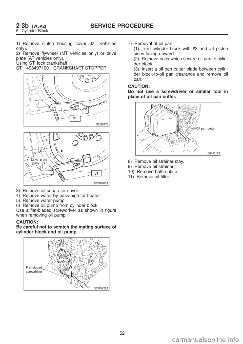
1) Remove clutch housing cover (MT vehicles
only).
2) Remove flywheel (MT vehicles only) or drive
plate (AT vehicles only).
Using ST, lock crankshaft.
ST 498497100 CRANKSHAFT STOPPER
G2M0776
B2M0706A
3) Remove oil separator cover.
4) Remove water by-pass pipe for heater.
5) Remove water pump.
6) Remove oil pump from cylinder block.
Use a flat-bladed screwdriver as shown in figure
when removing oil pump.
CAUTION:
Be careful not to scratch the mating surface of
cylinder block and oil pump.
S2M0722A
7) Removal of oil pan
(1) Turn cylinder block with #2 and #4 piston
sides facing upward.
(2) Remove bolts which secure oil pan to cylin-
der block.
(3) Insert a oil pan cutter blade between cylin-
der block-to-oil pan clearance and remove oil
pan.
CAUTION:
Do not use a screwdriver or similar tool in
place of oil pan cutter.
G2M0163
8) Remove oil strainer stay.
9) Remove oil strainer.
10) Remove baffle plate.
11) Remove oil filter.
52
2-3b[W5A2]SERVICE PROCEDURE
5. Cylinder Block
Page 201 of 1456
(2) Apply fluid packing to matching surface of
oil pump.
Fluid packing:
THREE BOND 1215 or equivalent
B2M0390A
(3) Install oil pump on cylinder block. Be care-
ful not to damage oil seal during installation.
CAUTION:
IDo not forget to install O-ring and seal when
installing oil pump.
IAlign flat surface of oil pump's inner rotor
with crankshaft before installation.
B2M0390A
9) Install water pump and gasket.
CAUTION:
IBe sure to use a new gasket.
IWhen installing water pump, tighten bolts in
two stages in alphabetical sequence as shown
in figure.
H2M1568A
10) Install water by-pass pipe for heater.
11) Install oil filter.
2. RELATED PARTS
1) Install water pipe.
CAUTION:
Always use a new O-ring.
S2M0308A
2) Install cylinder heads.
3) Install camshafts, rocker cover and related
parts.
4) Install camshaft sprockets, timing belt and
related parts.
70
2-3b[W5E2]SERVICE PROCEDURE
5. Cylinder Block
Page 232 of 1456
1. Water Pump
B2M1188A
(1) Water pump ASSY
(2) Gasket
(3) Heater hose
(4) Thermostat
(5) Gasket(6) Thermostat caseTightening torque: N´m (kg-m, ft-lb)
T1:
First 10+4/þ0
(1.0+0.4/þ0, 7.2+2.9/þ0)
Second 10+4/þ0
(1.0+0.4/þ0, 7.2+2.9/þ0)
T2:6.4±0.5 (0.65±0.05, 4.7±0.4)
4
2-5[C100]COMPONENT PARTS
1. Water Pump
Page 238 of 1456
5) Disconnect radiator outlet hose (A) and heater
by-pass hose (B) from water pump.
H2M2515A
6) Disconnect connectors from radiator main fan
(A) and sub fan (B) motors.
B2M2035A
7) Lower the vehicles.
8) Remove radiator main fan
[W6A0].> and sub fan motor assembly
[W7A0].>.
B2M2036
9) Remove V-belts.
B2M2308
10) Remove timing belt.
B2M2037
11) Remove automatic belt tension adjuster.
H2M2375
12) Remove belt idler No. 2.
H2M2518
13) Remove camshaft position sensor.
B2M2038
9
[W2A1]2-5SERVICE PROCEDURE
2. Water Pump
Page 239 of 1456
14) Remove left-hand camshaft sprocket by using
ST.
ST 499207100 CAMSHAFT SPROCKET
WRENCH
B2M2039A
15) Remove left-hand belt cover No. 2.
B2M2040
16) Remove tensioner bracket.
H2M2380
17) Remove tensioner bracket.
18) Disconnect heater hose from water pump.
19) Remove water pump.
G2M0210
20) Installation is in the reverse order of removal.
CAUTION:
IReplace gasket with a new one.
IWhen installing water pump, tighten bolts in
two stages in alphabetical sequence as shown
in figure.
Tightening torque:
10+4/þ0N´m (1.0+0.4/þ0kg-m, 7.2+2.9/þ0ft-lb)
S2M0760A
2. 2500 cc MODEL
1) Disconnect ground cable from the battery.
B2M1723
2) Lift-up the vehicle.
3) Remove under cover.
B2M0014
10
2-5[W2A2]SERVICE PROCEDURE
2. Water Pump