Page 967 of 1456

1. Precaution
A: SUPPLEMENTAL RESTRAINT
SYSTEM ªAIRBAGº
CAUTION:
IAll Airbag system wiring harness and con-
nectors are colored yellow. Do not use electri-
cal test equipment on these circuit.
IBe careful not to damage Airbag system wir-
ing harness when servicing the instrument
panel, heater unit, blower motor and control
unit.
Airbag system wiring harness is routed near the
instrument panel, heater unit, blower motor and
control unit.
2. Heater Unit
A: REMOVAL AND INSTALLATION
1) Disconnect GND cable from battery.
2) Remove heater hoses (inlet, outlet) in engine
compartment.
NOTE:
Drain as much coolant from heater unit as
possible, and plug disconnected hose with cloth.
3) Remove instrument panel.
[W1A0].>
4) Remove steering support beam.
[C600].>
5) Remove evaporator. (With A/C model)
4-7 [W14A0].>
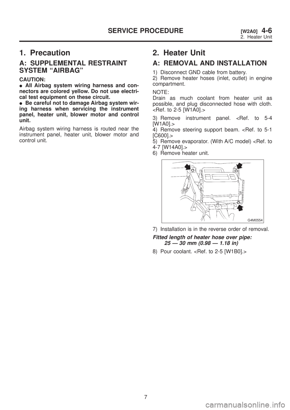
6) Remove heater unit.
G4M0554
7) Installation is in the reverse order of removal.
Fitted length of heater hose over pipe:
25 Ð 30 mm (0.98 Ð 1.18 in)
8) Pour coolant.
7
[W2A0]4-6SERVICE PROCEDURE
2. Heater Unit
Page 968 of 1456

1. Precaution
A: SUPPLEMENTAL RESTRAINT
SYSTEM ªAIRBAGº
CAUTION:
IAll Airbag system wiring harness and con-
nectors are colored yellow. Do not use electri-
cal test equipment on these circuit.
IBe careful not to damage Airbag system wir-
ing harness when servicing the instrument
panel, heater unit, blower motor and control
unit.
Airbag system wiring harness is routed near the
instrument panel, heater unit, blower motor and
control unit.
2. Heater Unit
A: REMOVAL AND INSTALLATION
1) Disconnect GND cable from battery.
2) Remove heater hoses (inlet, outlet) in engine
compartment.
NOTE:
Drain as much coolant from heater unit as
possible, and plug disconnected hose with cloth.
3) Remove instrument panel.
[W1A0].>
4) Remove steering support beam.
[C600].>
5) Remove evaporator. (With A/C model)
4-7 [W14A0].>
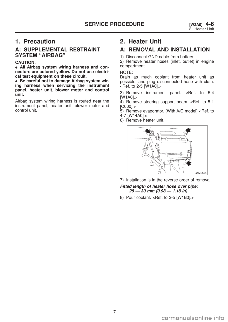
6) Remove heater unit.
G4M0554
7) Installation is in the reverse order of removal.
Fitted length of heater hose over pipe:
25 Ð 30 mm (0.98 Ð 1.18 in)
8) Pour coolant.
7
[W2A0]4-6SERVICE PROCEDURE
2. Heater Unit
Page 969 of 1456
3. Blower Motor Assembly
A: REMOVAL AND INSTALLATION
1) Disconnect GND cable from battery.
2) Remove glove box and pocket back panel.
3) Disconnect blower motor harness connector.
B5M0025
4) Disconnect aspirator pipe (A).
5) Remove blower motor mounting screw.
B4M1082B
6) Remove blower motor assembly.
7) Installation is in the reverse order of removal.
4. Control Unit
A: REMOVAL AND INSTALLATION
1) Disconnect GND cable from battery.
2) Set temperature control lever to ªFULL COLDº
position.
3) Remove temperature control cable from heater
unit.
NOTE:
Do not attempt to move link of heater unit during
installation.
B5M0027
4) Remove cup holder.
5) Remove center panel and then disconnect con-
nector.
B4M0370
6) Remove control unit assembly and disconnect
connector.
B4M0059
7) Installation is in the reverse order of removal.
NOTE:
Before control unit installation, set temperature
control lever to ªFULL COLDº position.
8
4-6[W3A0]SERVICE PROCEDURE
3. Blower Motor Assembly
Page 970 of 1456
3. Blower Motor Assembly
A: REMOVAL AND INSTALLATION
1) Disconnect GND cable from battery.
2) Remove glove box and pocket back panel.
3) Disconnect blower motor harness connector.
B5M0025
4) Disconnect aspirator pipe (A).
5) Remove blower motor mounting screw.
B4M1082B
6) Remove blower motor assembly.
7) Installation is in the reverse order of removal.
4. Control Unit
A: REMOVAL AND INSTALLATION
1) Disconnect GND cable from battery.
2) Set temperature control lever to ªFULL COLDº
position.
3) Remove temperature control cable from heater
unit.
NOTE:
Do not attempt to move link of heater unit during
installation.
B5M0027
4) Remove cup holder.
5) Remove center panel and then disconnect con-
nector.
B4M0370
6) Remove control unit assembly and disconnect
connector.
B4M0059
7) Installation is in the reverse order of removal.
NOTE:
Before control unit installation, set temperature
control lever to ªFULL COLDº position.
8
4-6[W3A0]SERVICE PROCEDURE
3. Blower Motor Assembly
Page 972 of 1456
C: ADJUSTMENT
1) Operate temperature control lever to ªFULL
COLDº position.
2) Install control cable to lever (A). While pushing
outer cable, secure control cable with clip (B).
B4M0062C
5. Intake Door Motor
A: REMOVAL AND INSTALLATION
1) Disconnect GND cable from battery.
2) Remove glove box and pocket back panel.
B5M0025
3) Remove heater duct or evaporator. (With A/C
model).
4) Remove intake unit from the vehicle.
G4M0561
10
4-6[W4C0]SERVICE PROCEDURE
5. Intake Door Motor
Page 973 of 1456
C: ADJUSTMENT
1) Operate temperature control lever to ªFULL
COLDº position.
2) Install control cable to lever (A). While pushing
outer cable, secure control cable with clip (B).
B4M0062C
5. Intake Door Motor
A: REMOVAL AND INSTALLATION
1) Disconnect GND cable from battery.
2) Remove glove box and pocket back panel.
B5M0025
3) Remove heater duct or evaporator. (With A/C
model).
4) Remove intake unit from the vehicle.
G4M0561
10
4-6[W4C0]SERVICE PROCEDURE
5. Intake Door Motor
Page 1073 of 1456

Process
No.Process name Job contents
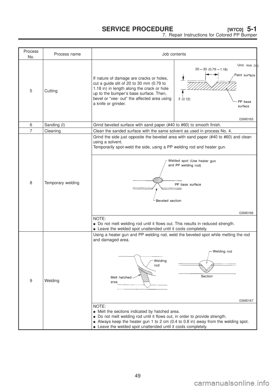
5 CuttingIf nature of damage are cracks or holes,
cut a guide slit of 20 to 30 mm (0.79 to
1.18 in) in length along the crack or hole
up to the bumper's base surface. Then,
bevel or ªvee- outº the affected area using
a knife or grinder.
G5M0165
6 Sanding (I) Grind beveled surface with sand paper (#40 to #60) to smooth finish.
7 Cleaning Clean the sanded surface with the same solvent as used in process No. 4.
8 Temporary weldingGrind the side just opposite the beveled area with sand paper (#40 to #60) and clean
using a solvent.
Temporarily spot-weld the side, using a PP welding rod and heater gun.
G5M0166
NOTE:
IDo not melt welding rod until it flows out. This results in reduced strength.
ILeave the welded spot unattended until it cools completely.
9 WeldingUsing a heater gun and PP welding rod, weld the beveled spot while melting the rod
and damaged area.
G5M0167
NOTE:
IMelt the sections indicated by hatched area.
IDo not melt welding rod until it flows out, in order to provide strength.
IAlways keep the heater gun 1 to 2 cm (0.4 to 0.8 in) away from the welding spot.
ILeave the welded spot unattended until it cools completely.
49
[W7C0]5-1SERVICE PROCEDURE
7. Repair Instructions for Colored PP Bumper
Page 1157 of 1456

7) Remove rear quarter pillar lower trim.
B5M0045
8) Installation is in the reverse order of removal.
CAUTION:
Be careful not to ride trim panel over harness,
insulators, etc.
9. ROOF TRIM
NOTE:
1) Remove room mirror, room light, sun visor and
assist grip.
2) Remove front pillar upper, center pillar upper,
rear quarter upper and rear rail trim.
3) Using ST, remove clips and then detach roof
trim.
ST 925580000 PULLER
B5M0050
4) Installation is in the reverse order of removal.
CAUTION:
When removing clip, use great care to prevent
damaging the roof trim.
10. FLOOR MAT
1) Supplemental Restraint System ªAirbagº
Airbag system wiring harness is routed near floor
mat.
CAUTION:
IAll Airbag system wiring harness and con-
nectors are colored yellow. Do not use electri-
cal test equipment on these circuit.
IBe careful not to damage Airbag system wir-
ing harness when servicing floor mat.
2) The following procedure is applicable to all
models:
NOTE:
(8) Remove clip under front seat.
(9) Remove clip in toe board area.
NOTE:
When pulling out edge, do not pull mat alone; pull
mat together with edge.
Pry off two steel clips on side sill front cover and
one on side sill rear cover using screwdriver.
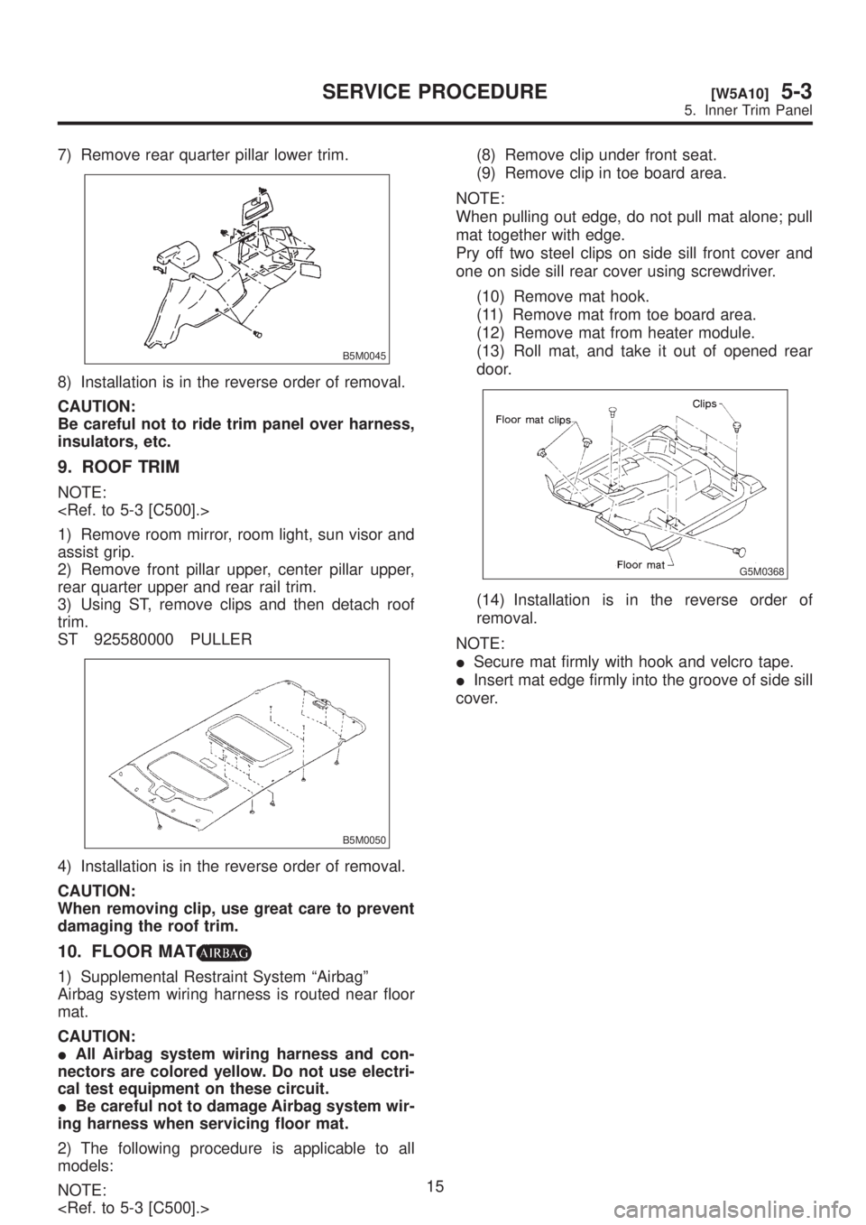
(10) Remove mat hook.
(11) Remove mat from toe board area.
(12) Remove mat from heater module.
(13) Roll mat, and take it out of opened rear
door.
G5M0368
(14) Installation is in the reverse order of
removal.
NOTE:
ISecure mat firmly with hook and velcro tape.
IInsert mat edge firmly into the groove of side sill
cover.
15
[W5A10]5-3SERVICE PROCEDURE
5. Inner Trim Panel