Page 1161 of 1456
1. Instrument Panel
A: REMOVAL
Airbag system wiring harness is routed near com-
bination meter.
CAUTION:
IAll Airbag system wiring harness and con-
nectors are colored yellow. Do not use electri-
cal test equipment on these circuits.
IBe careful not to damage Airbag system wir-
ing harness when servicing the combination
meter.
1) Disconnect GND cable from battery.
2) Remove shift knob (MT model).
3) Remove console cover (A) and front cover (B).
B5M0022C
4) Remove console box.
B5M0023
5) Remove lower cover and then disconnect con-
nector.
B5M0024A
6) Remove glove box.
B5M0025
7) Remove cover back panel.
B5M0026
8) Remove two bolts and lower steering column.
G5M0278
9) Set temperature control lever to Max. COLD
position, and then disconnect temperature control
cable from link of heater module.
NOTE:
Do not move lever and link when installing.
B5M0027
4
5-4[W1A0]SERVICE PROCEDURE
1. Instrument Panel
Page 1196 of 1456
2. Generator
A: REMOVAL AND INSTALLATION
1) Disconnect battery ground cable.
B2M1723
2) Disconnect connector and terminal from gen-
erator.
B6M0864
3) Remove V-belt covers.
B6M0865
4) Remove front side V-belt.
G2M0286
5) Remove bolts which install generator onto
bracket.
B6M0866
6) Installation is in the reverse order of removal.
CAUTION:
Check and adjust V-belt tension.
[G2A0].>
B6M0866
B: DISASSEMBLY
1) Heat the portion (A) of rear cover to 50ÉC
(122ÉF) with heater drier.
B6M0476B
15
[W2B0]6-1SERVICE PROCEDURE
2. Generator
Page 1201 of 1456

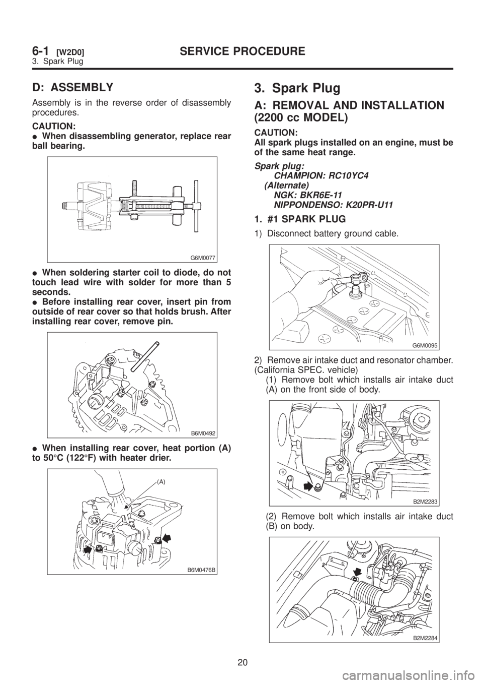
D: ASSEMBLY
Assembly is in the reverse order of disassembly
procedures.
CAUTION:
IWhen disassembling generator, replace rear
ball bearing.
G6M0077
IWhen soldering starter coil to diode, do not
touch lead wire with solder for more than 5
seconds.
IBefore installing rear cover, insert pin from
outside of rear cover so that holds brush. After
installing rear cover, remove pin.
B6M0492
IWhen installing rear cover, heat portion (A)
to 50ÉC (122ÉF) with heater drier.
B6M0476B
3. Spark Plug
A: REMOVAL AND INSTALLATION
(2200 cc MODEL)
CAUTION:
All spark plugs installed on an engine, must be
of the same heat range.
Spark plug:
CHAMPION: RC10YC4
(Alternate)
NGK: BKR6E-11
NIPPONDENSO: K20PR-U11
1. #1 SPARK PLUG
1) Disconnect battery ground cable.
G6M0095
2) Remove air intake duct and resonator chamber.
(California SPEC. vehicle)
(1) Remove bolt which installs air intake duct
(A) on the front side of body.
B2M2283
(2) Remove bolt which installs air intake duct
(B) on body.
B2M2284
20
6-1[W2D0]SERVICE PROCEDURE
3. Spark Plug
Page 1202 of 1456

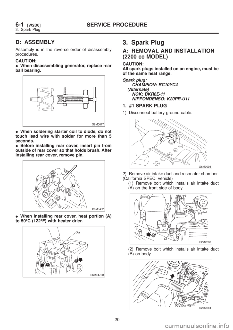
D: ASSEMBLY
Assembly is in the reverse order of disassembly
procedures.
CAUTION:
IWhen disassembling generator, replace rear
ball bearing.
G6M0077
IWhen soldering starter coil to diode, do not
touch lead wire with solder for more than 5
seconds.
IBefore installing rear cover, insert pin from
outside of rear cover so that holds brush. After
installing rear cover, remove pin.
B6M0492
IWhen installing rear cover, heat portion (A)
to 50ÉC (122ÉF) with heater drier.
B6M0476B
3. Spark Plug
A: REMOVAL AND INSTALLATION
(2200 cc MODEL)
CAUTION:
All spark plugs installed on an engine, must be
of the same heat range.
Spark plug:
CHAMPION: RC10YC4
(Alternate)
NGK: BKR6E-11
NIPPONDENSO: K20PR-U11
1. #1 SPARK PLUG
1) Disconnect battery ground cable.
G6M0095
2) Remove air intake duct and resonator chamber.
(California SPEC. vehicle)
(1) Remove bolt which installs air intake duct
(A) on the front side of body.
B2M2283
(2) Remove bolt which installs air intake duct
(B) on body.
B2M2284
20
6-1[W2D0]SERVICE PROCEDURE
3. Spark Plug
Page 1265 of 1456

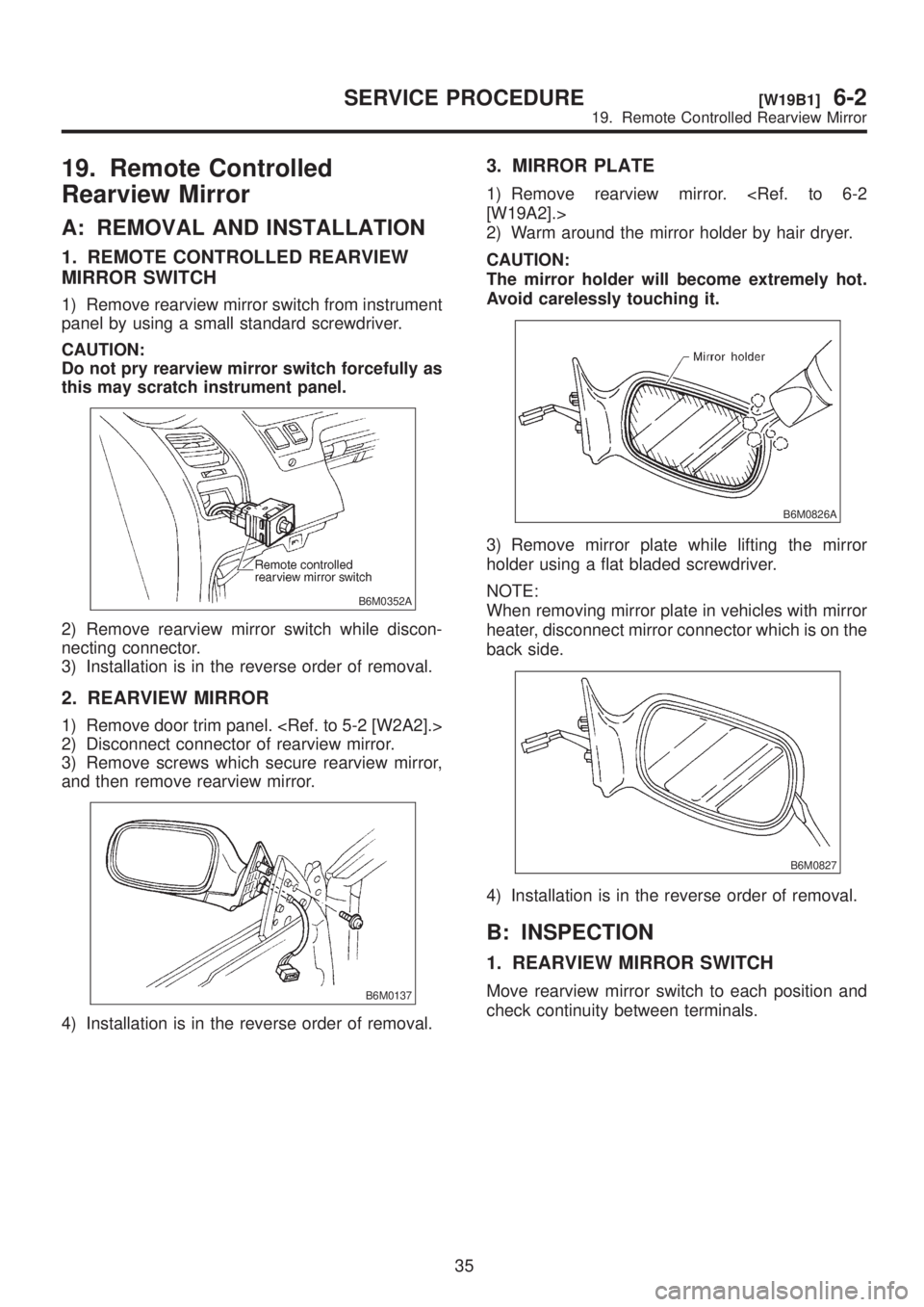
19. Remote Controlled
Rearview Mirror
A: REMOVAL AND INSTALLATION
1. REMOTE CONTROLLED REARVIEW
MIRROR SWITCH
1) Remove rearview mirror switch from instrument
panel by using a small standard screwdriver.
CAUTION:
Do not pry rearview mirror switch forcefully as
this may scratch instrument panel.
B6M0352A
2) Remove rearview mirror switch while discon-
necting connector.
3) Installation is in the reverse order of removal.
2. REARVIEW MIRROR
1) Remove door trim panel.
2) Disconnect connector of rearview mirror.
3) Remove screws which secure rearview mirror,
and then remove rearview mirror.
B6M0137
4) Installation is in the reverse order of removal.
3. MIRROR PLATE
1) Remove rearview mirror.
[W19A2].>
2) Warm around the mirror holder by hair dryer.
CAUTION:
The mirror holder will become extremely hot.
Avoid carelessly touching it.
B6M0826A
3) Remove mirror plate while lifting the mirror
holder using a flat bladed screwdriver.
NOTE:
When removing mirror plate in vehicles with mirror
heater, disconnect mirror connector which is on the
back side.
B6M0827
4) Installation is in the reverse order of removal.
B: INSPECTION
1. REARVIEW MIRROR SWITCH
Move rearview mirror switch to each position and
check continuity between terminals.
35
[W19B1]6-2SERVICE PROCEDURE
19. Remote Controlled Rearview Mirror
Page 1276 of 1456
24. Seat Heater
A: REMOVAL AND INSTALLATION
1. SEAT HEATER
Remove and install front seat (including heater
system).
2. SEAT HEATER SWITCH
1) Remove screws which secure rear console
cover, and then remove rear console cover.
2) Remove seat heater switch from console cover.
B6M0150A
3) Installation is in the reverse order of removal.
B: INSPECTION
1. SEAT HEATER
Check continuity between terminals of seat heater
connector:
IBetween terminals No. 1 and No. 3
IBetween terminals No. 1 and No. 4
IBetween terminals No. 3 and No. 4
B6M0151A
2. SEAT HEATER SWITCH
Set switch to each position and check continuity
between terminals.
B6M0845A
45
[W24B2]6-2SERVICE PROCEDURE
24. Seat Heater
Page 1296 of 1456

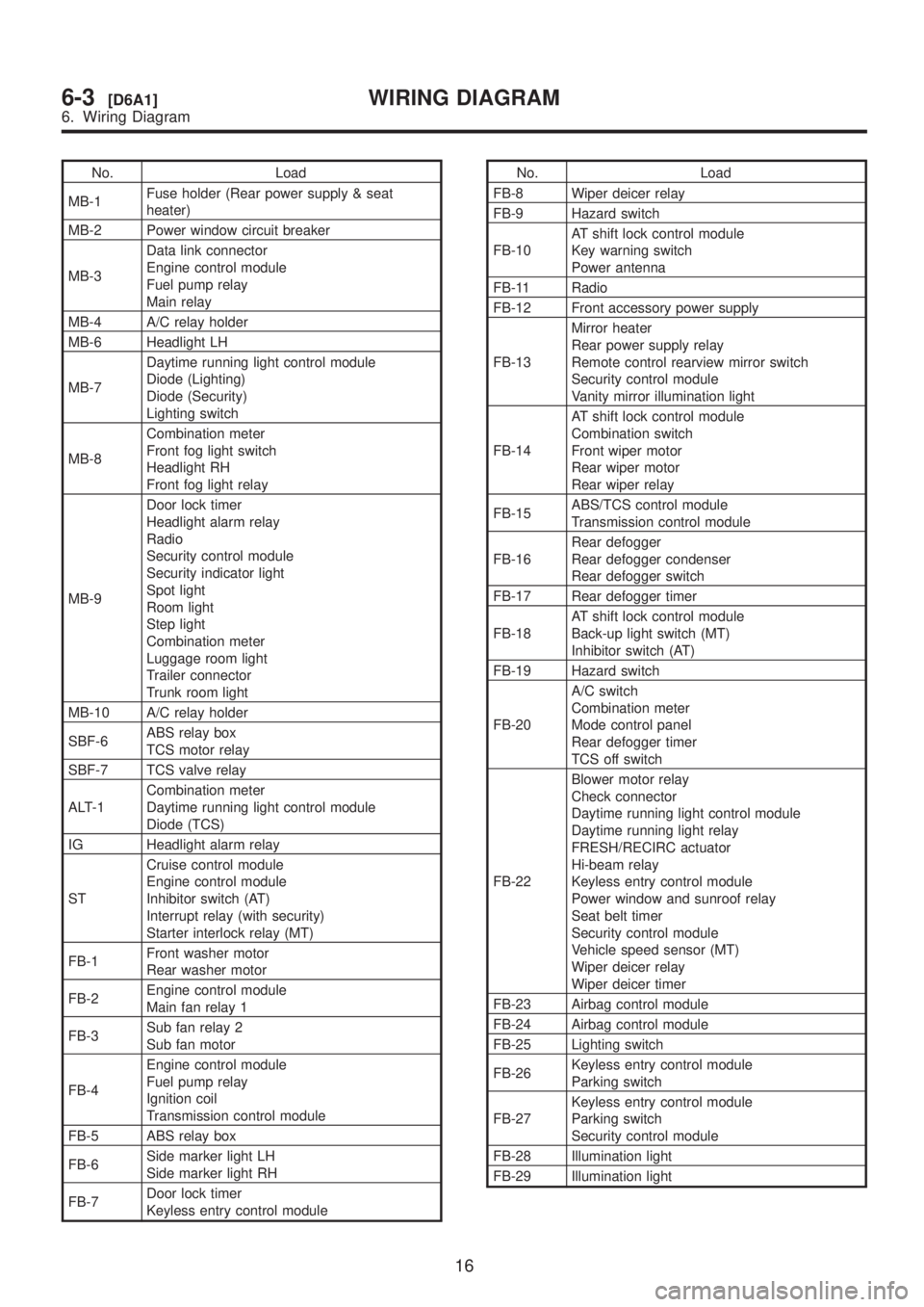
No. Load
MB-1Fuse holder (Rear power supply & seat
heater)
MB-2 Power window circuit breaker
MB-3Data link connector
Engine control module
Fuel pump relay
Main relay
MB-4 A/C relay holder
MB-6 Headlight LH
MB-7Daytime running light control module
Diode (Lighting)
Diode (Security)
Lighting switch
MB-8Combination meter
Front fog light switch
Headlight RH
Front fog light relay
MB-9Door lock timer
Headlight alarm relay
Radio
Security control module
Security indicator light
Spot light
Room light
Step light
Combination meter
Luggage room light
Trailer connector
Trunk room light
MB-10 A/C relay holder
SBF-6ABS relay box
TCS motor relay
SBF-7 TCS valve relay
ALT-1Combination meter
Daytime running light control module
Diode (TCS)
IG Headlight alarm relay
STCruise control module
Engine control module
Inhibitor switch (AT)
Interrupt relay (with security)
Starter interlock relay (MT)
FB-1Front washer motor
Rear washer motor
FB-2Engine control module
Main fan relay 1
FB-3Sub fan relay 2
Sub fan motor
FB-4Engine control module
Fuel pump relay
Ignition coil
Transmission control module
FB-5 ABS relay box
FB-6Side marker light LH
Side marker light RH
FB-7Door lock timer
Keyless entry control moduleNo. Load
FB-8 Wiper deicer relay
FB-9 Hazard switch
FB-10AT shift lock control module
Key warning switch
Power antenna
FB-11 Radio
FB-12 Front accessory power supply
FB-13Mirror heater
Rear power supply relay
Remote control rearview mirror switch
Security control module
Vanity mirror illumination light
FB-14AT shift lock control module
Combination switch
Front wiper motor
Rear wiper motor
Rear wiper relay
FB-15ABS/TCS control module
Transmission control module
FB-16Rear defogger
Rear defogger condenser
Rear defogger switch
FB-17 Rear defogger timer
FB-18AT shift lock control module
Back-up light switch (MT)
Inhibitor switch (AT)
FB-19 Hazard switch
FB-20A/C switch
Combination meter
Mode control panel
Rear defogger timer
TCS off switch
FB-22Blower motor relay
Check connector
Daytime running light control module
Daytime running light relay
FRESH/RECIRC actuator
Hi-beam relay
Keyless entry control module
Power window and sunroof relay
Seat belt timer
Security control module
Vehicle speed sensor (MT)
Wiper deicer relay
Wiper deicer timer
FB-23 Airbag control module
FB-24 Airbag control module
FB-25 Lighting switch
FB-26Keyless entry control module
Parking switch
FB-27Keyless entry control module
Parking switch
Security control module
FB-28 Illumination light
FB-29 Illumination light
16
6-3[D6A1]WIRING DIAGRAM
6. Wiring Diagram
Page 1396 of 1456
AD: SEAT HEATER SYSTEM
11 6
6-3[D6AD0]WIRING DIAGRAM
6. Wiring Diagram