1999 SUBARU LEGACY specifications
[x] Cancel search: specificationsPage 137 of 1456
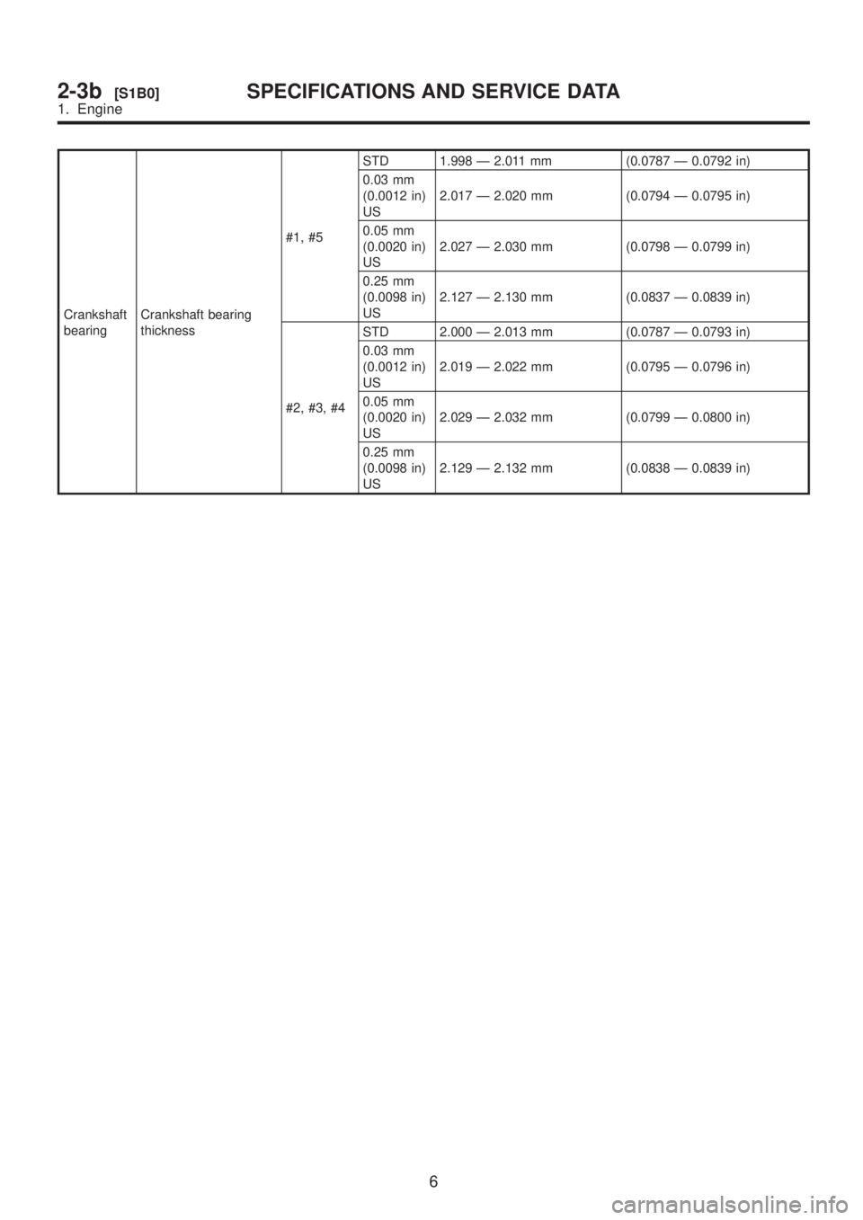
Crankshaft
bearingCrankshaft bearing
thickness#1, #5STD 1.998 Ð 2.011 mm (0.0787 Ð 0.0792 in)
0.03 mm
(0.0012 in)
US2.017 Ð 2.020 mm (0.0794 Ð 0.0795 in)
0.05 mm
(0.0020 in)
US2.027 Ð 2.030 mm (0.0798 Ð 0.0799 in)
0.25 mm
(0.0098 in)
US2.127 Ð 2.130 mm (0.0837 Ð 0.0839 in)
#2, #3, #4STD 2.000 Ð 2.013 mm (0.0787 Ð 0.0793 in)
0.03 mm
(0.0012 in)
US2.019 Ð 2.022 mm (0.0795 Ð 0.0796 in)
0.05 mm
(0.0020 in)
US2.029 Ð 2.032 mm (0.0799 Ð 0.0800 in)
0.25 mm
(0.0098 in)
US2.129 Ð 2.132 mm (0.0838 Ð 0.0839 in)
6
2-3b[S1B0]SPECIFICATIONS AND SERVICE DATA
1. Engine
Page 151 of 1456

(1) Slowly press the adjuster rod down to the
end surface of the cylinder. Repeat this motion
2 or 3 times.
(2) With the adjuster rod moved all the way up,
apply a pressure of 294 N (30 kg, 66 lb) to it.
Check adjuster rod stiffness.
(3) If the adjuster rod is not stiff and moves
down, replace the automatic belt tension
adjuster assembly with a new one.
CAUTION:
IAlways use a vertical type pressing tool to
move the adjuster rod down.
IDo not use a lateral type vise.
IPush adjuster rod vertically.
IPress-in the push adjuster rod gradually tak-
ing more than three minutes.
IDo not allow press pressure to exceed 9,807
N (1,000 kg, 2,205 lb).
IPress the adjuster rod as far as the end sur-
face of the cylinder. Do not press the adjuster
rod into the cylinder. Doing so may damage the
cylinder.
4) Measure the extension of rod beyond the body.
If it is not within specifications, replace with a new
one.
Rod extension: H
5.7
±0.5 mm (0.224±0.020 in)
H2M2381A
3. BELT TENSION PULLEY
1) Check mating surfaces of timing belt and con-
tact point of adjuster rod for abnormal wear or
scratches. Replace belt tension pulley if faulty.
2) Check belt tension pulley for smooth rotation.
Replace if noise or excessive play is noted.
3) Check belt tension pulley for grease leakage.
4. BELT IDLER
1) Check idler for smooth rotation. Replace if
noise or excessive play is noted.
2) Check outer contacting surfaces of idler pulley
for abnormal wear and scratches.
3) Check idler for grease leakage.
5. SPROCKET
1) Check sprocket teeth for abnormal wear and
scratches.
2) Make sure there is no free play between
sprocket and key.
3) Check crankshaft sprocket notch for sensor for
damage and contamination of foreign matter.
20
2-3b[W2B3]SERVICE PROCEDURE
2. Timing Belt
Page 172 of 1456
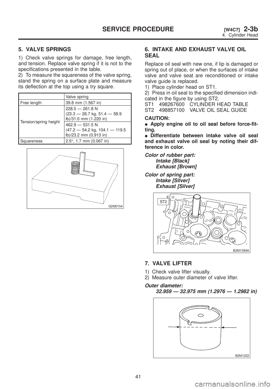
5. VALVE SPRINGS
1) Check valve springs for damage, free length,
and tension. Replace valve spring if it is not to the
specifications presented in the table.
2) To measure the squareness of the valve spring,
stand the spring on a surface plate and measure
its deflection at the top using a try square.
Valve spring
Free length 39.8 mm (1.567 in)
Tension/spring height228.5 Ð 261.8 N
(23.3 Ð 26.7 kg, 51.4 Ð 58.9
lb)/31.0 mm (1.220 in)
462.9 Ð 531.5 N
(47.2 Ð 54.2 kg, 104.1 Ð 119.5
lb)/23.2 mm (0.913 in)
Squareness 2.5É, 1.7 mm (0.067 in)
G2M0154
6. INTAKE AND EXHAUST VALVE OIL
SEAL
Replace oil seal with new one, if lip is damaged or
spring out of place, or when the surfaces of intake
valve and valve seat are reconditioned or intake
valve guide is replaced.
1) Place cylinder head on ST1.
2) Press in oil seal to the specified dimension indi-
cated in the figure by using ST2.
ST1 498267600 CYLINDER HEAD TABLE
ST2 498857100 VALVE OIL SEAL GUIDE
CAUTION:
IApply engine oil to oil seal before force-fit-
ting.
IDifferentiate between intake valve oil seal
and exhaust valve oil seal by noting their dif-
ference in color.
Color of rubber part:
Intake [Black]
Exhaust [Brown]
Color of spring part:
Intake [Silver]
Exhaust [Silver]
B2M1399A
7. VALVE LIFTER
1) Check valve lifter visually.
2) Measure outer diameter of valve lifter.
Outer diameter:
32.959 Ð 32.975 mm (1.2976 Ð 1.2982 in)
B2M1222
41
[W4C7]2-3bSERVICE PROCEDURE
4. Cylinder Head
Page 191 of 1456
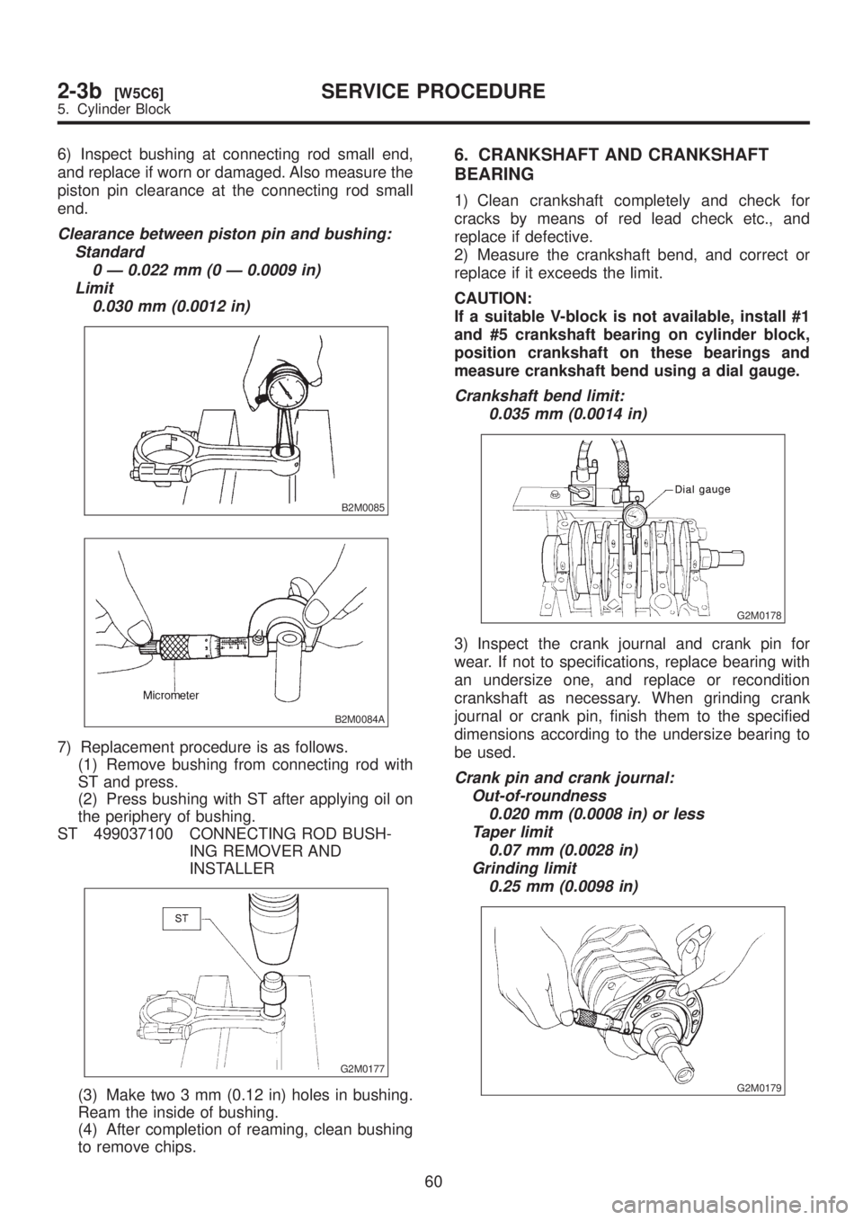
6) Inspect bushing at connecting rod small end,
and replace if worn or damaged. Also measure the
piston pin clearance at the connecting rod small
end.
Clearance between piston pin and bushing:
Standard
0 Ð 0.022 mm (0 Ð 0.0009 in)
Limit
0.030 mm (0.0012 in)
B2M0085
B2M0084A
7) Replacement procedure is as follows.
(1) Remove bushing from connecting rod with
ST and press.
(2) Press bushing with ST after applying oil on
the periphery of bushing.
ST 499037100 CONNECTING ROD BUSH-
ING REMOVER AND
INSTALLER
G2M0177
(3) Make two 3 mm (0.12 in) holes in bushing.
Ream the inside of bushing.
(4) After completion of reaming, clean bushing
to remove chips.
6. CRANKSHAFT AND CRANKSHAFT
BEARING
1) Clean crankshaft completely and check for
cracks by means of red lead check etc., and
replace if defective.
2) Measure the crankshaft bend, and correct or
replace if it exceeds the limit.
CAUTION:
If a suitable V-block is not available, install #1
and #5 crankshaft bearing on cylinder block,
position crankshaft on these bearings and
measure crankshaft bend using a dial gauge.
Crankshaft bend limit:
0.035 mm (0.0014 in)
G2M0178
3) Inspect the crank journal and crank pin for
wear. If not to specifications, replace bearing with
an undersize one, and replace or recondition
crankshaft as necessary. When grinding crank
journal or crank pin, finish them to the specified
dimensions according to the undersize bearing to
be used.
Crank pin and crank journal:
Out-of-roundness
0.020 mm (0.0008 in) or less
Taper limit
0.07 mm (0.0028 in)
Grinding limit
0.25 mm (0.0098 in)
G2M0179
60
2-3b[W5C6]SERVICE PROCEDURE
5. Cylinder Block
Page 208 of 1456
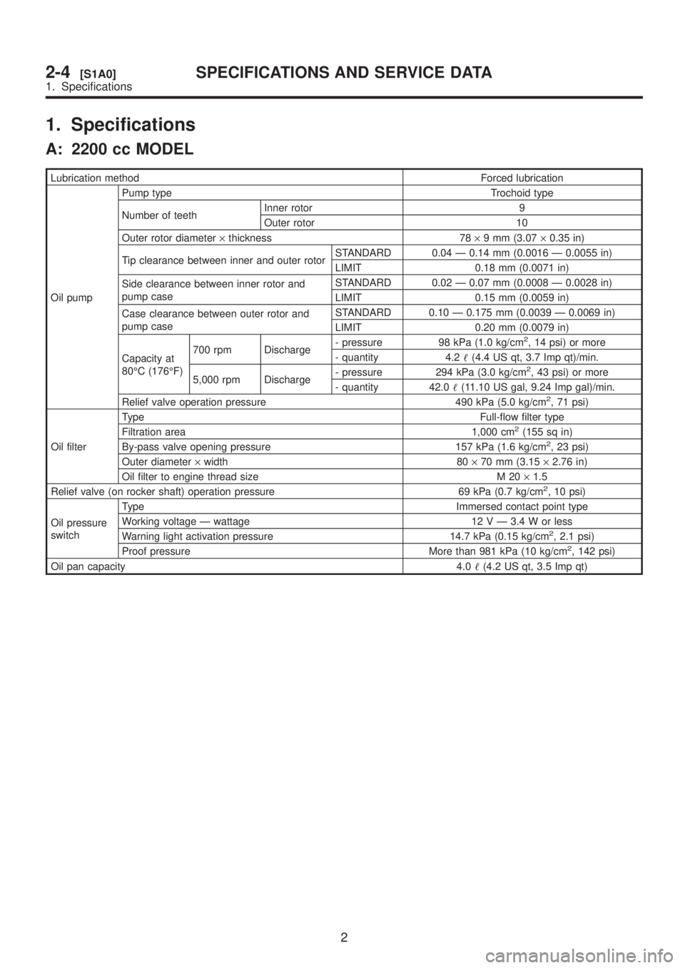
1. Specifications
A: 2200 cc MODEL
Lubrication methodForced lubrication
Oil pumpPump type Trochoid type
Number of teethInner rotor 9
Outer rotor 10
Outer rotor diameter´thickness 78´9 mm (3.07´0.35 in)
Tip clearance between inner and outer rotorSTANDARD 0.04 Ð 0.14 mm (0.0016 Ð 0.0055 in)
LIMIT 0.18 mm (0.0071 in)
Side clearance between inner rotor and
pump caseSTANDARD 0.02 Ð 0.07 mm (0.0008 Ð 0.0028 in)
LIMIT 0.15 mm (0.0059 in)
Case clearance between outer rotor and
pump caseSTANDARD 0.10 Ð 0.175 mm (0.0039 Ð 0.0069 in)
LIMIT 0.20 mm (0.0079 in)
Capacity at
80ÉC (176ÉF)700 rpm Discharge- pressure 98 kPa (1.0 kg/cm
2, 14 psi) or more
- quantity 4.2(4.4 US qt, 3.7 Imp qt)/min.
5,000 rpm Discharge- pressure 294 kPa (3.0 kg/cm
2, 43 psi) or more
- quantity 42.0(11.10 US gal, 9.24 Imp gal)/min.
Relief valve operation pressure 490 kPa (5.0 kg/cm
2, 71 psi)
Oil filterTypeFull-flow filter type
Filtration area 1,000 cm
2(155 sq in)
By-pass valve opening pressure 157 kPa (1.6 kg/cm2, 23 psi)
Outer diameter´width 80´70 mm (3.15´2.76 in)
Oil filter to engine thread size M 20´1.5
Relief valve (on rocker shaft) operation pressure 69 kPa (0.7 kg/cm
2, 10 psi)
Oil pressure
switchType Immersed contact point type
Working voltage Ð wattage 12 V Ð 3.4 W or less
Warning light activation pressure 14.7 kPa (0.15 kg/cm
2, 2.1 psi)
Proof pressure More than 981 kPa (10 kg/cm2, 142 psi)
Oil pan capacity4.0(4.2 US qt, 3.5 Imp qt)
2
2-4[S1A0]SPECIFICATIONS AND SERVICE DATA
1. Specifications
Page 209 of 1456
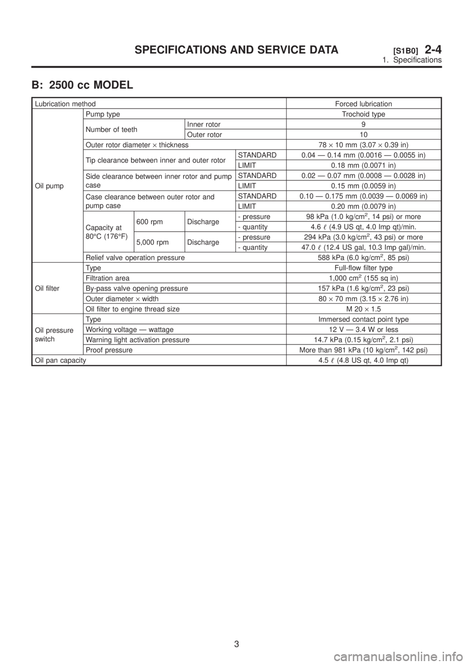
B: 2500 cc MODEL
Lubrication methodForced lubrication
Oil pumpPump type Trochoid type
Number of teethInner rotor 9
Outer rotor 10
Outer rotor diameter´thickness 78´10 mm (3.07´0.39 in)
Tip clearance between inner and outer rotorSTANDARD 0.04 Ð 0.14 mm (0.0016 Ð 0.0055 in)
LIMIT 0.18 mm (0.0071 in)
Side clearance between inner rotor and pump
caseSTANDARD 0.02 Ð 0.07 mm (0.0008 Ð 0.0028 in)
LIMIT 0.15 mm (0.0059 in)
Case clearance between outer rotor and
pump caseSTANDARD 0.10 Ð 0.175 mm (0.0039 Ð 0.0069 in)
LIMIT 0.20 mm (0.0079 in)
Capacity at
80ÉC (176ÉF)600 rpm Discharge- pressure 98 kPa (1.0 kg/cm
2, 14 psi) or more
- quantity 4.6(4.9 US qt, 4.0 Imp qt)/min.
5,000 rpm Discharge- pressure 294 kPa (3.0 kg/cm
2, 43 psi) or more
- quantity 47.0(12.4 US gal, 10.3 Imp gal)/min.
Relief valve operation pressure 588 kPa (6.0 kg/cm
2, 85 psi)
Oil filterTypeFull-flow filter type
Filtration area 1,000 cm
2(155 sq in)
By-pass valve opening pressure 157 kPa (1.6 kg/cm2, 23 psi)
Outer diameter´width 80´70 mm (3.15´2.76 in)
Oil filter to engine thread size M 20´1.5
Oil pressure
switchType Immersed contact point type
Working voltage Ð wattage 12 V Ð 3.4 W or less
Warning light activation pressure 14.7 kPa (0.15 kg/cm
2, 2.1 psi)
Proof pressure More than 981 kPa (10 kg/cm2, 142 psi)
Oil pan capacity4.5(4.8 US qt, 4.0 Imp qt)
3
[S1B0]2-4SPECIFICATIONS AND SERVICE DATA
1. Specifications
Page 229 of 1456
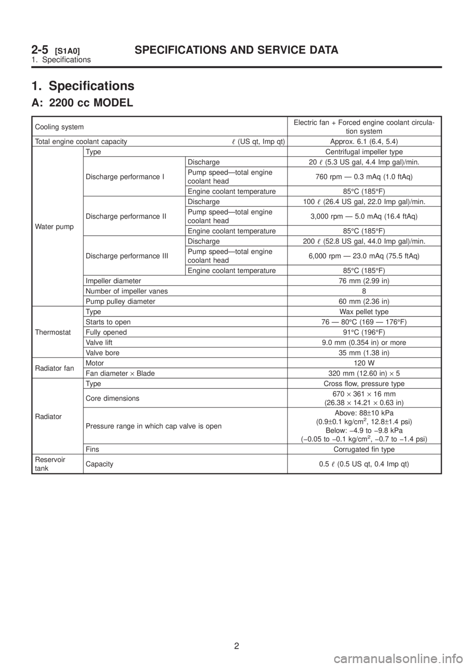
1. Specifications
A: 2200 cc MODEL
Cooling systemElectric fan + Forced engine coolant circula-
tion system
Total engine coolant capacity(US qt, Imp qt) Approx. 6.1 (6.4, 5.4)
Water pumpType Centrifugal impeller type
Discharge performance IDischarge 20(5.3 US gal, 4.4 Imp gal)/min.
Pump speedÐtotal engine
coolant head760 rpm Ð 0.3 mAq (1.0 ftAq)
Engine coolant temperature 85ÉC (185ÉF)
Discharge performance IIDischarge 100(26.4 US gal, 22.0 Imp gal)/min.
Pump speedÐtotal engine
coolant head3,000 rpm Ð 5.0 mAq (16.4 ftAq)
Engine coolant temperature 85ÉC (185ÉF)
Discharge performance IIIDischarge 200(52.8 US gal, 44.0 Imp gal)/min.
Pump speedÐtotal engine
coolant head6,000 rpm Ð 23.0 mAq (75.5 ftAq)
Engine coolant temperature 85ÉC (185ÉF)
Impeller diameter 76 mm (2.99 in)
Number of impeller vanes 8
Pump pulley diameter 60 mm (2.36 in)
ThermostatTypeWax pellet type
Starts to open 76 Ð 80ÉC (169 Ð 176ÉF)
Fully opened 91ÉC (196ÉF)
Valve lift 9.0 mm (0.354 in) or more
Valve bore 35 mm (1.38 in)
Radiator fanMotor120 W
Fan diameter´Blade 320 mm (12.60 in)´5
RadiatorType Cross flow, pressure type
Core dimensions670´361´16 mm
(26.38´14.21´0.63 in)
Pressure range in which cap valve is openAbove: 88±10 kPa
(0.9±0.1 kg/cm
2, 12.8±1.4 psi)
Below: þ4.9 to þ9.8 kPa
(þ0.05 to þ0.1 kg/cm
2, þ0.7 to þ1.4 psi)
FinsCorrugated fin type
Reservoir
tankCapacity 0.5(0.5 US qt, 0.4 Imp qt)
2
2-5[S1A0]SPECIFICATIONS AND SERVICE DATA
1. Specifications
Page 230 of 1456

B: 2500 cc MODEL
Cooling systemElectric fan + Forced engine coolant circula-
tion system
Total engine coolant capacity(US qt, Imp qt) Approx. 6.1 (6.4, 5.4)
Water pumpType Centrifugal impeller type
Discharge performance IDischarge 20(5.3 US gal, 4.4 Imp gal)/min.
Pump speedÐtotal engine
coolant head760 rpm Ð 0.3 mAq (1.0 ftAq)
Engine coolant temperature 85ÉC (185ÉF)
Discharge performance IIDischarge 100(26.4 US gal, 22.0 Imp gal)/min.
Pump speedÐtotal engine
coolant head3,000 rpm Ð 5.0 mAq (16.4 ftAq)
Engine coolant temperature 85ÉC (185ÉF)
Discharge performance IIIDischarge 200(52.8 US gal, 44.0 Imp gal)/min.
Pump speedÐtotal engine
coolant head6,000 rpm Ð 23.0 mAq (75.5 ftAq)
Engine coolant temperature 85ÉC (185ÉF)
Impeller diameter 76 mm (2.99 in)
Number of impeller vanes 8
Pump pulley diameter 60 mm (2.36 in)
ThermostatTypeWax pellet type
Starts to open 76 Ð 80ÉC (169 Ð 176ÉF)
Fully opened 91ÉC (196ÉF)
Valve lift 9.0 mm (0.354 in) or more
Valve bore 35 mm (1.38 in)
Radiator fanMotor120 W (main fan)
140 W (sub fan)
Fan diameter´Blade340 mm (13.39 in)´5 (main fan)
280 mm (11.02 in)´4 (sub fan)
RadiatorType Cross flow, pressure type
Core dimensions670´361´16 mm
(26.38´14.21´0.63 in)
Pressure range in which cap valve is openAbove: 88±10 kPa
(0.9±0.1 kg/cm
2, 12.8±1.4 psi)
Below: þ4.9 to þ9.8 kPa
(þ0.05 to þ0.1 kg/cm
2, þ0.7 to þ1.4 psi)
FinsCorrugated fin type
Reservoir
tankCapacity 0.5(0.5 US qt, 0.4 Imp qt)
2. Service Data
Water pump
Clearance between impeller and caseStandard0.5 Ð 0.7 mm (0.020 Ð 0.028
in)
Limit 1.0 mm (0.039 in)
ªThrustº runout of impeller end 0.5 mm (0.020 in)
3
[S200]2-5SPECIFICATIONS AND SERVICE DATA
2. Service Data