Page 1060 of 1456

1. Hood
A: REMOVAL AND INSTALLATION
NOTE:
The hood lock has a dual locking design which
consists of a main lock and a safety lock mecha-
nism. When the release knob located at the front
pillar on the driver's side is pulled back, the main
lock is released through the cable attached to the
knob.
The safety lock can be released by pushing the
lever protruding above the front grill while opening
the hood.
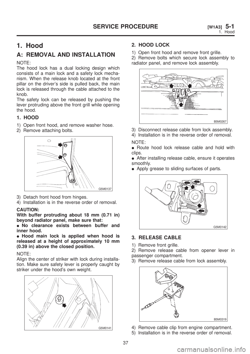
1. HOOD
1) Open front hood, and remove washer hose.
2) Remove attaching bolts.
G5M0137
3) Detach front hood from hinges.
4) Installation is in the reverse order of removal.
CAUTION:
With buffer protruding about 18 mm (0.71 in)
beyond radiator panel, make sure that:
INo clearance exists between buffer and
inner hood.
IHood main lock is applied when hood is
released at a height of approximately 10 mm
(0.39 in) above the closed position.
NOTE:
Align the center of striker with lock during installa-
tion. Make sure safety lever is properly caught by
striker under the hood's own weight.
G5M0141
2. HOOD LOCK
1) Open front hood and remove front grille.
2) Remove bolts which secure lock assembly to
radiator panel, and remove lock assembly.
B5M0267
3) Disconnect release cable from lock assembly.
4) Installation is in the reverse order of removal.
NOTE:
IRoute hood lock release cable and hold with
clips.
IAfter installing release cable, ensure it operates
smoothly.
IApply grease to sliding surfaces of parts.
G5M0142
3. RELEASE CABLE
1) Remove front grille.
2) Remove release cable from opener lever in
passenger compartment.
3) Remove release cable from lock assembly.
B5M0319
4) Remove cable clip from engine compartment.
5) Installation is in the reverse order of removal.
37
[W1A3]5-1SERVICE PROCEDURE
1. Hood
Page 1287 of 1456

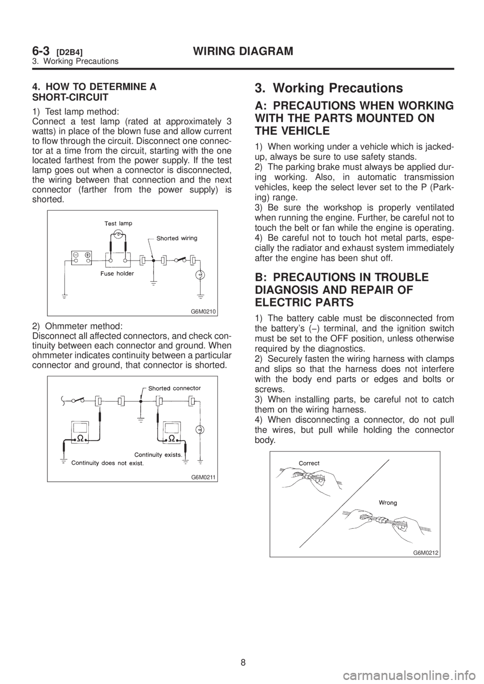
4. HOW TO DETERMINE A
SHORT-CIRCUIT
1) Test lamp method:
Connect a test lamp (rated at approximately 3
watts) in place of the blown fuse and allow current
to flow through the circuit. Disconnect one connec-
tor at a time from the circuit, starting with the one
located farthest from the power supply. If the test
lamp goes out when a connector is disconnected,
the wiring between that connection and the next
connector (farther from the power supply) is
shorted.
G6M0210
2) Ohmmeter method:
Disconnect all affected connectors, and check con-
tinuity between each connector and ground. When
ohmmeter indicates continuity between a particular
connector and ground, that connector is shorted.
G6M0211
3. Working Precautions
A: PRECAUTIONS WHEN WORKING
WITH THE PARTS MOUNTED ON
THE VEHICLE
1) When working under a vehicle which is jacked-
up, always be sure to use safety stands.
2) The parking brake must always be applied dur-
ing working. Also, in automatic transmission
vehicles, keep the select lever set to the P (Park-
ing) range.
3) Be sure the workshop is properly ventilated
when running the engine. Further, be careful not to
touch the belt or fan while the engine is operating.
4) Be careful not to touch hot metal parts, espe-
cially the radiator and exhaust system immediately
after the engine has been shut off.
B: PRECAUTIONS IN TROUBLE
DIAGNOSIS AND REPAIR OF
ELECTRIC PARTS
1) The battery cable must be disconnected from
the battery's (þ) terminal, and the ignition switch
must be set to the OFF position, unless otherwise
required by the diagnostics.
2) Securely fasten the wiring harness with clamps
and slips so that the harness does not interfere
with the body end parts or edges and bolts or
screws.
3) When installing parts, be careful not to catch
them on the wiring harness.
4) When disconnecting a connector, do not pull
the wires, but pull while holding the connector
body.
G6M0212
8
6-3[D2B4]WIRING DIAGRAM
3. Working Precautions
Page 1288 of 1456

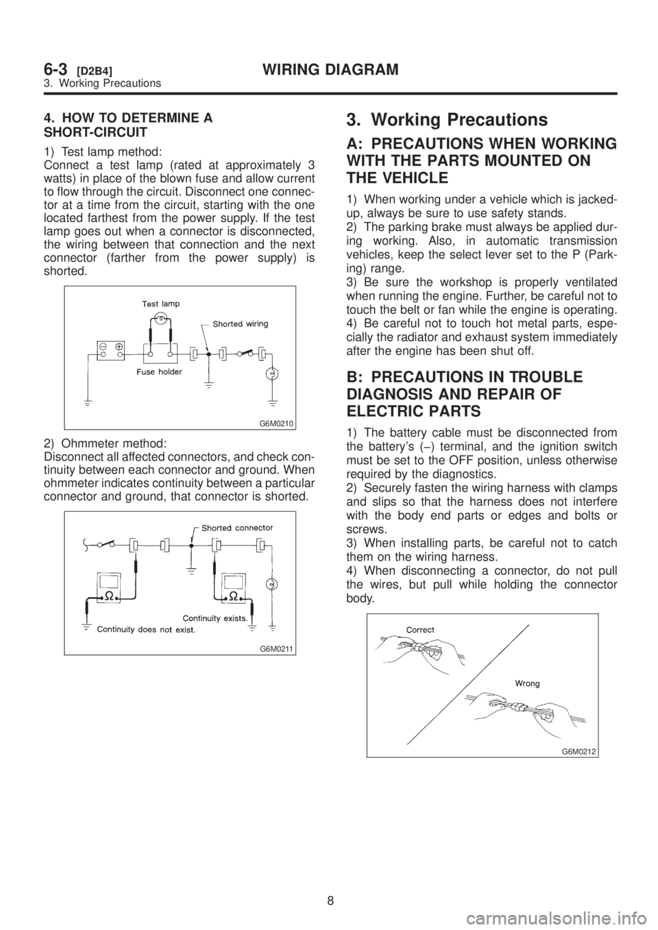
4. HOW TO DETERMINE A
SHORT-CIRCUIT
1) Test lamp method:
Connect a test lamp (rated at approximately 3
watts) in place of the blown fuse and allow current
to flow through the circuit. Disconnect one connec-
tor at a time from the circuit, starting with the one
located farthest from the power supply. If the test
lamp goes out when a connector is disconnected,
the wiring between that connection and the next
connector (farther from the power supply) is
shorted.
G6M0210
2) Ohmmeter method:
Disconnect all affected connectors, and check con-
tinuity between each connector and ground. When
ohmmeter indicates continuity between a particular
connector and ground, that connector is shorted.
G6M0211
3. Working Precautions
A: PRECAUTIONS WHEN WORKING
WITH THE PARTS MOUNTED ON
THE VEHICLE
1) When working under a vehicle which is jacked-
up, always be sure to use safety stands.
2) The parking brake must always be applied dur-
ing working. Also, in automatic transmission
vehicles, keep the select lever set to the P (Park-
ing) range.
3) Be sure the workshop is properly ventilated
when running the engine. Further, be careful not to
touch the belt or fan while the engine is operating.
4) Be careful not to touch hot metal parts, espe-
cially the radiator and exhaust system immediately
after the engine has been shut off.
B: PRECAUTIONS IN TROUBLE
DIAGNOSIS AND REPAIR OF
ELECTRIC PARTS
1) The battery cable must be disconnected from
the battery's (þ) terminal, and the ignition switch
must be set to the OFF position, unless otherwise
required by the diagnostics.
2) Securely fasten the wiring harness with clamps
and slips so that the harness does not interfere
with the body end parts or edges and bolts or
screws.
3) When installing parts, be careful not to catch
them on the wiring harness.
4) When disconnecting a connector, do not pull
the wires, but pull while holding the connector
body.
G6M0212
8
6-3[D2B4]WIRING DIAGRAM
3. Working Precautions
Page 1388 of 1456
Z: RADIATOR FAN SYSTEM
1. LHD MODEL
108
6-3[D6Z1]WIRING DIAGRAM
6. Wiring Diagram
Page 1422 of 1456

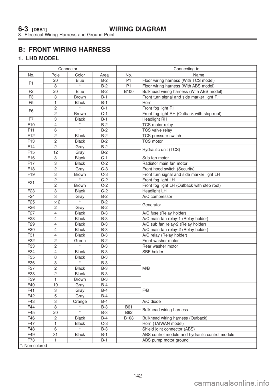
B: FRONT WIRING HARNESS
1. LHD MODEL
Connector Connecting to
No. Pole Color Area No. Name
F120 Blue B-2 P1 Floor wiring harness (With TCS model)
8 * B-2 P1 Floor wiring harness (With ABS model)
F2 20 Blue B-2 B100 Bulkhead wiring harness (With ABS model)
F3 3 Brown B-1 Front turn signal and side marker light RH
F5 1 Black B-1 Horn
F62 * C-1 Front fog light RH
2 Brown C-1 Front fog light RH (Outback with step roof)
F7 3 Black B-1 Headlight RH
F10 4 * B-2 TCS motor relay
F11 6 * B-2 TCS valve relay
F12 2 Black B-2 TCS pressure switch
F13 2 Black B-2 TCS motor
F14 2 Gray B-2
Hydraulic unit (TCS)
F15 12 Gray B-2
F16 3 Black C-1 Sub fan motor
F17 3 Black C-2 Radiator main fan motor
F18 2 Gray C-3 Front hood switch (Security)
F19 3 Brown C-3 Front turn signal and side marker light LH
F212 * C-2 Front fog light LH
2 Brown C-2 Front fog light LH (Outback with step roof)
F23 3 Black C-2 Headlight LH
F24 3 Gray B-2 A/C compressor
F25 1´2 * B-2
Generator
F26 2 Gray B-2
F27 4 Black B-3 A/C fuse (Relay holder)
F28 4 Black B-3 A/C main fan relay-1 (Relay holder)
F29 4 Black B-3 A/C sub fan relay-2 (Relay holder)
F30 4 Black B-3 A/C main fan relay-2 (Relay holder)
F31 4 Black B-3 A/C relay (Relay holder)
F32 2 Green B-2 Front washer motor
F33 2 * B-3 Rear washer motor
F34 4 Black B-3 SBF holder
F35 8 Black B-3
M/B F36 3 * B-3
F37 2 Black B-3
F38 2 Black B-3
F39 1 Brown B-3
F40 10 Gray B-4
F/B F41 3 Gray B-4
F42 5 Gray B-4
F43 3 Orange B-4 A/C diode
F44 8 * B-3 B61
Bulkhead wiring harness
F45 20 * B-3 B62
F46 2 Black B-4 B108 Bulkhead wiring harness (Outback)
F47 1 Black C-3 Horn (TAIWAN model)
F48 6 * B-3 Shield joint connector (ABS)
F49 31 Black B-1 ABS control module and hydraulic control module
F73 1 * B-1 ABS pump motor ground
*: Non-colored
142
6-3[D8B1]WIRING DIAGRAM
8. Electrical Wiring Harness and Ground Point
Page 1424 of 1456
2. RHD MODEL
Connector Connecting to
No. Pole Color Area No. Name
F3 3 Brown B-1 Front turn signal and side marker light RH
F5 1 Black B-1 Horn
F7 3 Black B-1 Headlight RH
F16 3 Black C-1 Sub fan motor
F17 3 Black C-2 Radiator main fan motor
F19 3 Brown C-3 Front turn signal and side marker light LH
F20 1 Black C-2 Horn
F23 3 Black C-2 Headlight LH
F24 1 Black B-2 A/C compressor
F25 1´2 * B-2
Generator
F26 2 Gray B-2
F27 4 Black B-3 A/C fuse (Relay holder)
F28 4 Black B-3 A/C main fan relay-1 (Relay holder)
F29 4 Black B-3 A/C sub fan relay-2 (Relay holder)
F30 4 Black B-3 A/C main fan relay-2 (Relay holder)
F31 4 Black B-3 A/C relay (Relay holder)
F35 8 Black B-3
M/B
F38 2 Black B-3
F40 10 Gray B-2
F/B
F42 5 Gray B-2
F43 3 Orange B-2 A/C diode
F44 8 * B-2 B61
Bulkhead wiring harness
F45 20 * B-2 B62
F47 2 Gray C-2 A/C pressure switch
F48 2 Blue B-2 Thermal protector
*: Non-colored
144
6-3[D8B2]WIRING DIAGRAM
8. Electrical Wiring Harness and Ground Point