Page 1006 of 1456

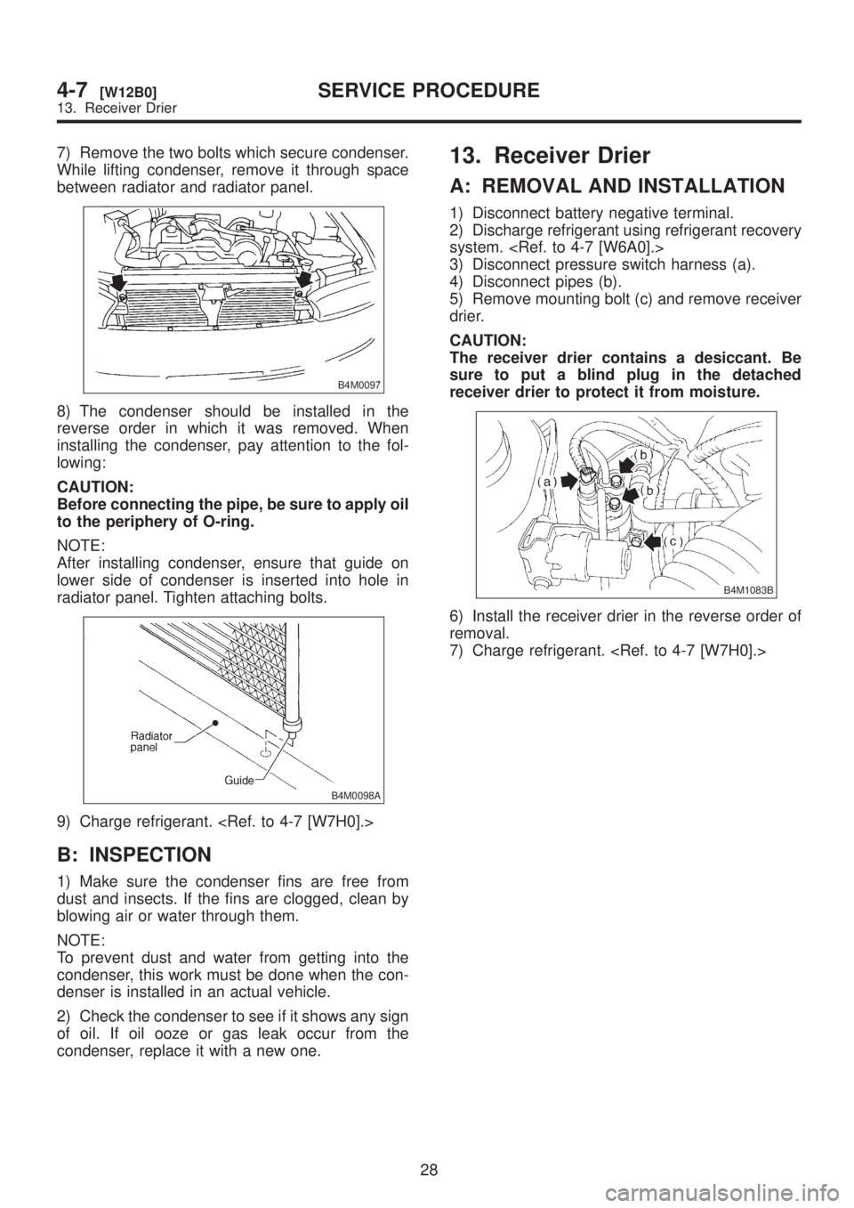
7) Remove the two bolts which secure condenser.
While lifting condenser, remove it through space
between radiator and radiator panel.
B4M0097
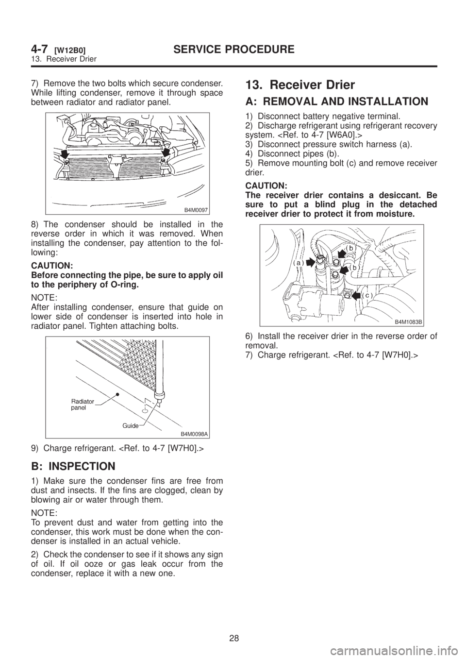
8) The condenser should be installed in the
reverse order in which it was removed. When
installing the condenser, pay attention to the fol-
lowing:
CAUTION:
Before connecting the pipe, be sure to apply oil
to the periphery of O-ring.
NOTE:
After installing condenser, ensure that guide on
lower side of condenser is inserted into hole in
radiator panel. Tighten attaching bolts.
B4M0098A
9) Charge refrigerant.
B: INSPECTION
1) Make sure the condenser fins are free from
dust and insects. If the fins are clogged, clean by
blowing air or water through them.
NOTE:
To prevent dust and water from getting into the
condenser, this work must be done when the con-
denser is installed in an actual vehicle.
2) Check the condenser to see if it shows any sign
of oil. If oil ooze or gas leak occur from the
condenser, replace it with a new one.
13. Receiver Drier
A: REMOVAL AND INSTALLATION
1) Disconnect battery negative terminal.
2) Discharge refrigerant using refrigerant recovery
system.
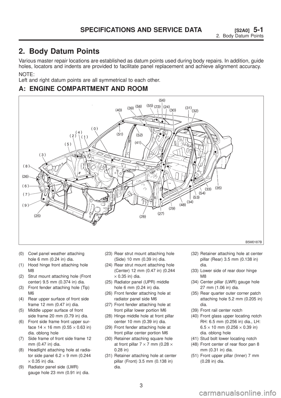
3) Disconnect pressure switch harness (a).
4) Disconnect pipes (b).
5) Remove mounting bolt (c) and remove receiver
drier.
CAUTION:
The receiver drier contains a desiccant. Be
sure to put a blind plug in the detached
receiver drier to protect it from moisture.
B4M1083B
6) Install the receiver drier in the reverse order of
removal.
7) Charge refrigerant.
28
4-7[W12B0]SERVICE PROCEDURE
13. Receiver Drier
Page 1007 of 1456

7) Remove the two bolts which secure condenser.
While lifting condenser, remove it through space
between radiator and radiator panel.
B4M0097
8) The condenser should be installed in the
reverse order in which it was removed. When
installing the condenser, pay attention to the fol-
lowing:
CAUTION:
Before connecting the pipe, be sure to apply oil
to the periphery of O-ring.
NOTE:
After installing condenser, ensure that guide on
lower side of condenser is inserted into hole in
radiator panel. Tighten attaching bolts.
B4M0098A
9) Charge refrigerant.
B: INSPECTION
1) Make sure the condenser fins are free from
dust and insects. If the fins are clogged, clean by
blowing air or water through them.
NOTE:
To prevent dust and water from getting into the
condenser, this work must be done when the con-
denser is installed in an actual vehicle.
2) Check the condenser to see if it shows any sign
of oil. If oil ooze or gas leak occur from the
condenser, replace it with a new one.
13. Receiver Drier
A: REMOVAL AND INSTALLATION
1) Disconnect battery negative terminal.
2) Discharge refrigerant using refrigerant recovery
system.
3) Disconnect pressure switch harness (a).
4) Disconnect pipes (b).
5) Remove mounting bolt (c) and remove receiver
drier.
CAUTION:
The receiver drier contains a desiccant. Be
sure to put a blind plug in the detached
receiver drier to protect it from moisture.
B4M1083B
6) Install the receiver drier in the reverse order of
removal.
7) Charge refrigerant.
28
4-7[W12B0]SERVICE PROCEDURE
13. Receiver Drier
Page 1009 of 1456
7) Check parts that have been removed for cracks
or scratches, and repair or replace them with new
ones, if necessary.
8) Reassemble the evaporator in the reverse
order of disassembly.
NOTE:
Confirm that the O-ring is inserted in the specified
position.15. Condenser Fan Assembly
A: REMOVAL AND INSTALLATION
1) Disconnect battery negative terminal.
2) Disconnect harness connector from fan motor.
3) Remove condenser fan bolt from radiator.
4) Pull condenser fan assembly.
5) Install the condenser fan assembly in the
reverse order of removal.
Tightening torque:
T: 7.4
±2.0 N´m (0.75±0.2 kg-m, 5.4±1.4
ft-lb)
B4M0102A
30
4-7[W15A0]SERVICE PROCEDURE
15. Condenser Fan Assembly
Page 1010 of 1456
7) Check parts that have been removed for cracks
or scratches, and repair or replace them with new
ones, if necessary.
8) Reassemble the evaporator in the reverse
order of disassembly.
NOTE:
Confirm that the O-ring is inserted in the specified
position.15. Condenser Fan Assembly
A: REMOVAL AND INSTALLATION
1) Disconnect battery negative terminal.
2) Disconnect harness connector from fan motor.
3) Remove condenser fan bolt from radiator.
4) Pull condenser fan assembly.
5) Install the condenser fan assembly in the
reverse order of removal.
Tightening torque:
T: 7.4
±2.0 N´m (0.75±0.2 kg-m, 5.4±1.4
ft-lb)
B4M0102A
30
4-7[W15A0]SERVICE PROCEDURE
15. Condenser Fan Assembly
Page 1012 of 1456
17. Relay and Fuse
A: LOCATION
Relays used with A/C system are located as shown
in figure.
IA/C relay
IMain fan (radiator fan) relay
ISub fan (condenser fan) relay
ISub fan (condenser fan) water temperature
relay
IFuses (10 A and 20 A)
G4M0649
B: INSPECTION
1) Check conduction with a circuit tester (ohm
range) according to the following table in figure.
G4M0651
2) Replace relays which do not meet specifica-
tions.
B4M0105A
32
4-7[W17A0]SERVICE PROCEDURE
17. Relay and Fuse
Page 1022 of 1456
6. Radiator Fan (Main Fan) Diagnosis
B4M1107A
42
4-7[K600]DIAGNOSTICS
6. Radiator Fan (Main Fan) Diagnosis
Page 1026 of 1456

2. Body Datum Points
Various master repair locations are established as datum points used during body repairs. In addition, guide
holes, locators and indents are provided to facilitate panel replacement and achieve alignment accuracy.
NOTE:
Left and right datum points are all symmetrical to each other.
A: ENGINE COMPARTMENT AND ROOM
B5M0187B
(0) Cowl panel weather attaching
hole 6 mm (0.24 in) dia.
(1) Hood hinge front attaching hole
M8
(2) Strut mount attaching hole (Front
center) 9.5 mm (0.374 in) dia.
(3) Front fender attaching hole (Tip)
M6
(4) Rear upper surface of front side
frame 12 mm (0.47 in) dia.
(5) Middle upper surface of front
side frame 20 mm (0.79 in) dia.
(6) Front side frame front upper sur-
face 14´16 mm (0.55´0.63 in)
dia. oblong hole
(7) Side frame of front side frame 12
mm (0.47 in) dia.
(8) Headlight attaching hole at radia-
tor side panel 6.2´9 mm (0.244
´0.35 in) dia.
(9) Radiator panel side (LWR)
gauge hole 23 mm (0.91 in) dia.(23) Rear strut mount attaching hole
(Side) 10 mm (0.39 in) dia.
(24) Rear strut mount attaching hole
(Center) 12 mm (0.47 in) (0.244
´0.35 in) dia.
(25) Radiator panel (UPR) middle
hole 6 mm (0.24 in) dia.
(26) Front fender attaching hole at
radiator panel side M6
(27) Front fender attaching hole at
front pillar lower portion M6
(28) Hinge middle hole at front pillar
center 10 mm (0.39 in) dia.
(29) Front fender attaching hole at
front pillar center portion M6
(30) Retainer attaching square hole
at front pillar 7´7 mm (0.28´
0.28 in)
(31) Retainer attaching hole at center
pillar (Front) 3.5 mm (0.138 in)
dia.(32) Retainer attaching hole at center
pillar (Rear) 3.5 mm (0.138 in)
dia.
(33) Lower side of rear door hinge
M8
(34) Center pillar (LWR) gauge hole
27 mm (1.06 in) dia.
(35) Rear quarter outer corner patch
attaching hole 5.2 mm (0.205 in)
dia.
(39) Front rail center notch
(40) Front glass upper locating notch
RH: 6.5 mm (0.256 in) dia., LH:
6.5´10 mm (0.256´0.39 in)
dia. oblong hole
(41) Stud bolt lower locating notch
(48) Front center of rear floor pan 8
mm (0.31 in) dia.
(51) Front upper pillar (Inner) 7 mm
(0.28 in) dia.
3
[S2A0]5-1SPECIFICATIONS AND SERVICE DATA
2. Body Datum Points
Page 1030 of 1456
C: UNDERBODY
B5M0190B
(10) Radiator panel (LWR) frame
gauge hole 10 mm (0.39 in) dia.
(11) Front side frame front lower sur-
face 20 mm (0.79 in) dia.
(12) Front side frame center lower
surface 20 mm (0.79 in) dia.
(13) Front suspension attaching hole
M14
(14) Suspension attaching bracket
M14(15) Front side frame rear lower cen-
ter surface 20 mm (0.79 in) dia.
(16) Transmission mount attaching
hole M10
(17) Front side frame rear lower sur-
face 15 mm (0.59 in) dia.
(18) Rear frame front M12
(19) Rear frame front hole 25 mm
(0.98 in) dia.(20) Rear crossmember attaching
hole M12
(21) Rear frame center hole 7 mm
(0.28 in) dia.
(22) Rear frame rear concave part 15
mm (0.59 in) dia.
7
[S2C0]5-1SPECIFICATIONS AND SERVICE DATA
2. Body Datum Points