Page 439 of 1456

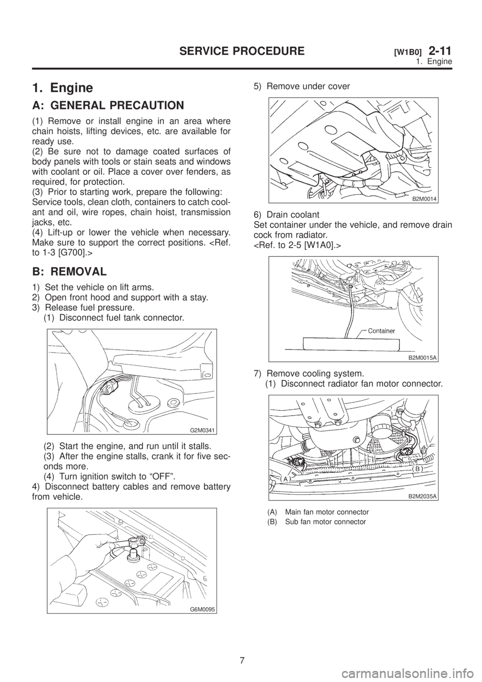
1. Engine
A: GENERAL PRECAUTION
(1) Remove or install engine in an area where
chain hoists, lifting devices, etc. are available for
ready use.
(2) Be sure not to damage coated surfaces of
body panels with tools or stain seats and windows
with coolant or oil. Place a cover over fenders, as
required, for protection.
(3) Prior to starting work, prepare the following:
Service tools, clean cloth, containers to catch cool-
ant and oil, wire ropes, chain hoist, transmission
jacks, etc.
(4) Lift-up or lower the vehicle when necessary.
Make sure to support the correct positions.
to 1-3 [G700].>
B: REMOVAL
1) Set the vehicle on lift arms.
2) Open front hood and support with a stay.
3) Release fuel pressure.
(1) Disconnect fuel tank connector.
G2M0341
(2) Start the engine, and run until it stalls.
(3) After the engine stalls, crank it for five sec-
onds more.
(4) Turn ignition switch to ªOFFº.
4) Disconnect battery cables and remove battery
from vehicle.
G6M0095
5) Remove under cover
B2M0014
6) Drain coolant
Set container under the vehicle, and remove drain
cock from radiator.
B2M0015A
7) Remove cooling system.
(1) Disconnect radiator fan motor connector.
B2M2035A
(A) Main fan motor connector
(B) Sub fan motor connector
7
[W1B0]2-11SERVICE PROCEDURE
1. Engine
Page 440 of 1456
(2) Disconnect radiator outlet hose from ther-
mostat cover.
H2M2515
(3) Remove reservoir tank.
S2M0028
(4) Disconnect ATF cooler hoses from pipes.
(AT vehicles)
B2M0016A
(5) Remove V-belt cover.
B2M2307
(6) Disconnect radiator inlet hose from radiator.
S2M0031
(7) Remove radiator upper bracket, and
remove radiator assembly from vehicle.
B2M2323
8) Collect refrigerant, and remove pressure hoses.
(With A/C)
(1) Place and connect the attachment hose to
the refrigerant recycle system.
(2) Collect refrigerant from A/C system.
(3) Disconnect A/C flexible hoses from A/C
compressor.
B2M2774
9) Remove air intake system.
(1) Disconnect connector from mass air flow
sensor.
(2) Remove air intake chamber, air intake duct
with air cleaner upper cover, and remove air
cleaner element. (Except 2200 cc California
spec. vehicles)
(3) Remove air cleaner case and duct. (2200 cc
California spec. vehicles)
and
8
2-11[W1B0]SERVICE PROCEDURE
1. Engine
Page 451 of 1456
(4) Clutch return spring (Models without hill
holder only)
CAUTION:
After connecting each cable, adjust them.
14) Install chamber stay.
15) Install air intake system.
(1) Install air cleaner element.
(2) Install air intake chamber and air intake duct
with air cleaner upper cover. (Except 2200 cc
California spec. vehicles)
(3) Connect connector to mass air flow sensor.
B2M2018
(4) Install air intake duct with air cleaner case.
(2200 cc California spec. vehicles)
[W1A0].> and
16) Install A/C flexible hoses. (With A/C)
CAUTION:
Use new O-rings.
Tightening torque:
25
±7 N´m (2.5±0.7 kg-m, 18.1±5.1 ft-lb)
B2M2774
17) Install cooling system.(1) Attach radiator mounting cushions to body.
B2M0307A
(2) Install radiator while fitting radiator pins to
cushions.
B2M2323
(3) Install radiator brackets and tighten bolts.
Tightening torque:
13.7
±1.5 N´m (1.4±0.15 kg-m, 10.1±1.1
ft-lb)
B2M0320
(4) Connect radiator fan motor connector.
H2M2515
19
[W1C0]2-11SERVICE PROCEDURE
1. Engine
Page 452 of 1456
(5) Connect radiator inlet hose.
S2M0031
(6) Connect radiator outlet hose.
(7) Connect ATF cooler hoses. (AT vehicles)
B2M0016A
(8) Install reservoir tank.
(9) Install V-belt cover.
B2M2307
18) Install under cover.
B2M0014
19) Install battery in the vehicle, and connect
cables.
20) Fill coolant.
Engine coolant capacity;
5.8
(6.1 US qt, 5.1 lmp qt)
21) Charge A/C system with refrigerant.
22) Remove front hood stay, and close front hood.
23) Take off the vehicle from lift arms.
20
2-11[W1C0]SERVICE PROCEDURE
1. Engine
Page 528 of 1456

Automatic
transmis-
sionTransmis-
sionSelector positionP (Park)Transmission in
neutral, output mem-
ber immovable, and
engine start possible
R (Reverse)Transmission in
reverse for backing
N (Neutral)Transmission in
neutral, and engine
start possible
D (Drive)Automatic gear
change
1st
¬
®2nd¬
®3rd¬
®4th
3 (3rd)Automatic gear
change
1st
¬
®2nd¬
®3rd
¬4th
2 (2nd)2nd gear locked
(Deceleration pos-
sible 4th®3rd®
2nd)
1 (1st)1st gear locked
(Deceleration pos-
sible 4th®3rd®
2nd®1st)
Control method Hydraulic remote control
Oil pumpType Trochoid constant-displacement pump
Driving method Driven by engine
Number of teethInner rotor 9
Outer rotor 10
Hydraulic
controlTypeElectronic/hydraulic control [Four forward speed changes by electri-
cal signals of vehicle speed and accelerator (throttle) opening]
Fluid Dexron II or Dexron III type Automatic transmission fluid
Fluid capacity2200 cc 8.4 Ð 8.7(8.9 Ð 9.2 US qt, 7.4 Ð 7.7 Imp qt)
2500 cc 9.3 Ð 9.6(9.8 Ð 10.1 US qt, 8.2 Ð 8.4 Imp qt)
Lubrica-
tionLubrication system Forced feed lubrication with oil pump
Oil Automatic transmission fluid (above mentioned.)
Cooling Cooling system Liquid-cooled cooler incorporated in radiator
HarnessInhibitor switch 12 poles
Transmission harness 17 poles
TransferTransfer clutch Hydraulic multi-plate clutch
Plate number of transfer clutchDrive plate & driven
plate2200 cc 4
2500 cc 5
Control method Electronic, hydraulic type
LubricantThe same Automatic Transmission
Fluid used in automatic transmission.
1st reduction gear ratio 1.000 (53/53)
3
[S1A0]3-2SPECIFICATIONS AND SERVICE DATA
1. Automatic Transmission and Differential
Page 976 of 1456

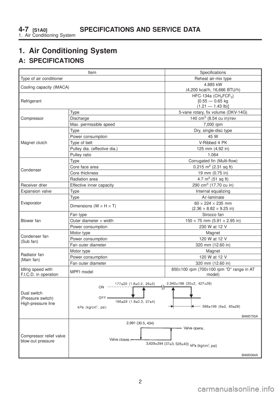
1. Air Conditioning System
A: SPECIFICATIONS
Item Specifications
Type of air conditioner Reheat air-mix type
Cooling capacity (IMACA)4.885 kW
(4,200 kcal/h, 16,666 BTU/h)
RefrigerantHFC-134a (CH
2FCF3)
[0.55 Ð 0.65 kg
(1.21 Ð 1.43 lb)]
CompressorType 5-vane rotary, fix volume (DKV-14G)
Discharge 140 cm
3(8.54 cu in)/rev
Max. permissible speed 7,000 rpm
Magnet clutchType Dry, single-disc type
Power consumption 45 W
Type of belt V-Ribbed 4 PK
Pulley dia. (effective dia.) 125 mm (4.92 in)
Pulley ratio 1.064
CondenserType Corrugated fin (Multi-flow)
Core face area 0.215 m
2(2.31 sq ft)
Core thickness 19 mm (0.75 in)
Radiation area 4.7 m
2(51 sq ft)
Receiver drier Effective inner capacity 290 cm3(17.70 cu in)
Expansion valve Type Internal equalizing
EvaporatorType A-laminate
Dimensions (W´H´T)60´224´235 mm
(2.36´8.82´9.25 in)
Blower fanFan type Sirocco fan
Outer diameter´width 150´75 mm (5.91´2.95 in)
Power consumption 230 W at 12 V
Condenser fan
(Sub fan)Motor type Magnet
Power consumption 120 W at 12 V
Fan outer diameter 320 mm (12.60 in)
Radiator fan
(Main fan)Motor type Magnet
Power consumption 120 W at 12 V
Fan outer diameter 320 mm (12.60 in)
Idling speed with
F.I.C.D. in operationMPFI model850±100 rpm (700±100 rpm ªDº range in AT
model)
Dual switch
(Pressure switch)
High-pressure line
B4M0755A
Compressor relief valve
blow-out pressure
B4M0084A
2
4-7[S1A0]SPECIFICATIONS AND SERVICE DATA
1. Air Conditioning System
Page 1004 of 1456
7) Install high-pressure hose (b).
Connect high-pressure hose with compressor.
CAUTION:
Be sure to apply compressor oil to the periph-
ery of O-ring.
B4M0761D
8) Install low-pressure hose (a).
Connect low-pressure hose with compressor.
CAUTION:
Be sure to apply compressor oil to the periph-
ery of O-ring.
B4M0761D
9) Install belt cover.
10) Connect ground cable to negative terminal of
battery.
11) Charge refrigerant.
12. Condenser
A: REMOVAL AND INSTALLATION
1) Disconnect battery negative terminal.
2) Discharge refrigerant using refrigerant recovery
system.
3) Remove front grille.
B4M0095
4) Remove canister from bracket.
CAUTION:
IDo not disconnect hose from canister.
IInsert air vent hose of canister into the hole
on body.
G2M0375
5) Remove the radiator upper bracket of both side.
6) Disconnect high-pressure hose (a) and high-
pressure pipe (b) from condenser.
B4M0096C
27
[W12A0]4-7SERVICE PROCEDURE
12. Condenser
Page 1005 of 1456
7) Install high-pressure hose (b).
Connect high-pressure hose with compressor.
CAUTION:
Be sure to apply compressor oil to the periph-
ery of O-ring.
B4M0761D
8) Install low-pressure hose (a).
Connect low-pressure hose with compressor.
CAUTION:
Be sure to apply compressor oil to the periph-
ery of O-ring.
B4M0761D
9) Install belt cover.
10) Connect ground cable to negative terminal of
battery.
11) Charge refrigerant.
12. Condenser
A: REMOVAL AND INSTALLATION
1) Disconnect battery negative terminal.
2) Discharge refrigerant using refrigerant recovery
system.
3) Remove front grille.
B4M0095
4) Remove canister from bracket.
CAUTION:
IDo not disconnect hose from canister.
IInsert air vent hose of canister into the hole
on body.
G2M0375
5) Remove the radiator upper bracket of both side.
6) Disconnect high-pressure hose (a) and high-
pressure pipe (b) from condenser.
B4M0096C
27
[W12A0]4-7SERVICE PROCEDURE
12. Condenser