Page 951 of 1456
1. Pedal
A: ON-CAR SERVICE
1. BRAKE PEDAL
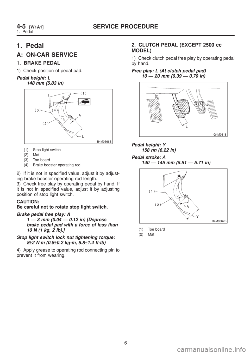
1) Check position of pedal pad.
Pedal height: L
148 mm (5.83 in)
B4M0366B
(1) Stop light switch
(2) Mat
(3) Toe board
(4) Brake booster operating rod
2) If it is not in specified value, adjust it by adjust-
ing brake booster operating rod length.
3) Check free play by operating pedal by hand. If
it is not in specified value, adjust it by adjusting
position of stop light switch.
CAUTION:
Be careful not to rotate stop light switch.
Brake pedal free play: A
1Ð3mm(0.04 Ð 0.12 in) [Depress
brake pedal pad with a force of less than
10 N (1 kg, 2 lb).]
Stop light switch lock nut tightening torque:
8
±2 N´m (0.8±0.2 kg-m, 5.8±1.4 ft-lb)
4) Apply grease to operating rod connecting pin to
prevent it from wearing.
2. CLUTCH PEDAL (EXCEPT 2500 cc
MODEL)
1) Check clutch pedal free play by operating pedal
by hand.
Free play: L (At clutch pedal pad)
10 Ð 20 mm (0.39 Ð 0.79 in)
G4M0318
Pedal height: Y
158 nn (6.22 in)
Pedal stroke: A
140 Ð 145 mm (5.51 Ð 5.71 in)
B4M0367B
(1) Toe board
(2) Mat
6
4-5[W1A1]SERVICE PROCEDURE
1. Pedal
Page 953 of 1456
B: REMOVAL
1. ACCELERATOR PEDAL
1) Disconnect ground cable from battery.
2) Disconnect accelerator cable from throttle body.
CAUTION:
Be careful not to kink accelerator cable.
3) Remove instrument panel lower cover from
instrument panel, and connector.
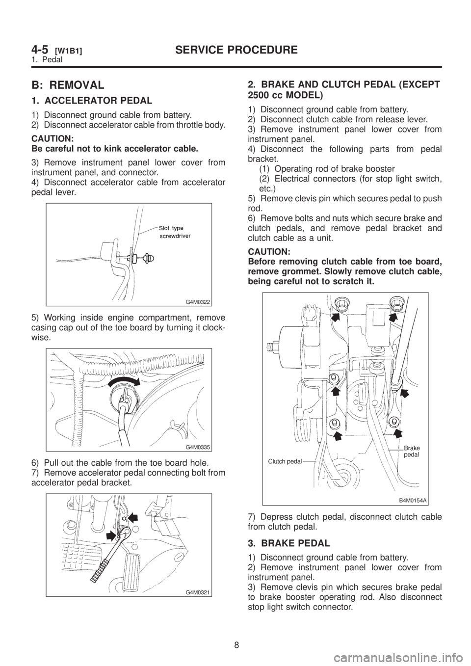
4) Disconnect accelerator cable from accelerator
pedal lever.
G4M0322
5) Working inside engine compartment, remove
casing cap out of the toe board by turning it clock-
wise.
G4M0335
6) Pull out the cable from the toe board hole.
7) Remove accelerator pedal connecting bolt from
accelerator pedal bracket.
G4M0321
2. BRAKE AND CLUTCH PEDAL (EXCEPT
2500 cc MODEL)
1) Disconnect ground cable from battery.
2) Disconnect clutch cable from release lever.
3) Remove instrument panel lower cover from
instrument panel.
4) Disconnect the following parts from pedal
bracket.
(1) Operating rod of brake booster
(2) Electrical connectors (for stop light switch,
etc.)
5) Remove clevis pin which secures pedal to push
rod.
6) Remove bolts and nuts which secure brake and
clutch pedals, and remove pedal bracket and
clutch cable as a unit.
CAUTION:
Before removing clutch cable from toe board,
remove grommet. Slowly remove clutch cable,
being careful not to scratch it.
B4M0154A
7) Depress clutch pedal, disconnect clutch cable
from clutch pedal.
3. BRAKE PEDAL
1) Disconnect ground cable from battery.
2) Remove instrument panel lower cover from
instrument panel.
3) Remove clevis pin which secures brake pedal
to brake booster operating rod. Also disconnect
stop light switch connector.
8
4-5[W1B1]SERVICE PROCEDURE
1. Pedal
Page 954 of 1456

4) Remove two bolts and four nuts which secure
brake pedal to pedal.
G4M0324
4. BRAKE AND CLUTCH PEDAL (2500 cc
MODEL)
1) Remove steering bolts.
2) Raise vehicle on hoist and remove the two bolts
which secure steering unit to underside of body.
3) Lower vehicle to floor.
4) Remove instrument panel lower cover from
instrument panel.
5) Disconnect the following parts from pedal
bracket.
IOperating rod of brake booster
IElectrical connectors (for stop light switch, etc.)
6) Remove clevis pin which secures lever to push
rod.
7) Remove nut which secures clutch master cylin-
der.
8) Remove steering assembly.
9) Remove bolts and nuts which secure brake and
clutch pedals, and remove pedal assembly.
C: INSPECTION
1. BRAKE AND CLUTCH PEDALS
Move brake and clutch pedal pads in the lateral
direction with a force of approximately 10 N (1 kg,
2 lb) to ensure pedal deflection is in specified
range.
Deflection of brake and clutch pedal:
Service limit
5.0 mm (0.197 in) or less
CAUTION:
If excessive deflection is noted, replace bush-
ings with new ones.
S4M0135A
G4M0326
9
[W1C1]4-5SERVICE PROCEDURE
1. Pedal
Page 955 of 1456
2. ACCELERATOR PEDAL
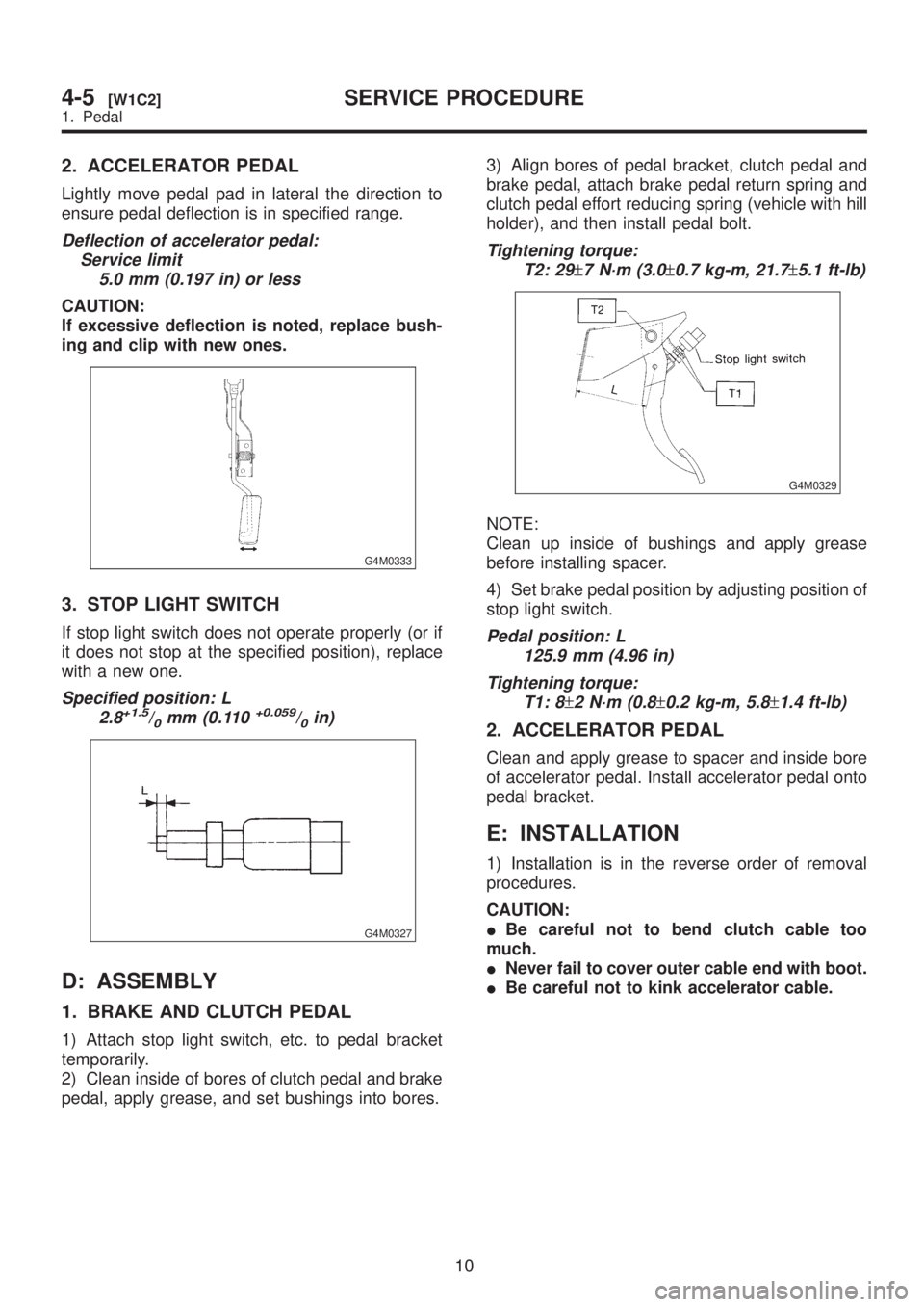
Lightly move pedal pad in lateral the direction to
ensure pedal deflection is in specified range.
Deflection of accelerator pedal:
Service limit
5.0 mm (0.197 in) or less
CAUTION:
If excessive deflection is noted, replace bush-
ing and clip with new ones.
G4M0333
3. STOP LIGHT SWITCH
If stop light switch does not operate properly (or if
it does not stop at the specified position), replace
with a new one.
Specified position: L
2.8+1.5/0mm (0.110+0.059/0in)
G4M0327
D: ASSEMBLY
1. BRAKE AND CLUTCH PEDAL
1) Attach stop light switch, etc. to pedal bracket
temporarily.
2) Clean inside of bores of clutch pedal and brake
pedal, apply grease, and set bushings into bores.3) Align bores of pedal bracket, clutch pedal and
brake pedal, attach brake pedal return spring and
clutch pedal effort reducing spring (vehicle with hill
holder), and then install pedal bolt.
Tightening torque:
T2: 29
±7 N´m (3.0±0.7 kg-m, 21.7±5.1 ft-lb)
G4M0329
NOTE:
Clean up inside of bushings and apply grease
before installing spacer.
4) Set brake pedal position by adjusting position of
stop light switch.
Pedal position: L
125.9 mm (4.96 in)
Tightening torque:
T1: 8
±2 N´m (0.8±0.2 kg-m, 5.8±1.4 ft-lb)
2. ACCELERATOR PEDAL
Clean and apply grease to spacer and inside bore
of accelerator pedal. Install accelerator pedal onto
pedal bracket.
E: INSTALLATION
1) Installation is in the reverse order of removal
procedures.
CAUTION:
IBe careful not to bend clutch cable too
much.
INever fail to cover outer cable end with boot.
IBe careful not to kink accelerator cable.
10
4-5[W1C2]SERVICE PROCEDURE
1. Pedal
Page 960 of 1456
1. Pedal System and Control Cables
Trouble Corrective action
Excessively worn brake pedal pad Replace.
Failure of clutch and/or accelerator pedals to operate Connect cables correctly.
Stop light switch does not light up. Adjust position of stop light switch.
Stop light switch is not smooth and/or stroke is not correct. Replace.
Insufficient pedal play Adjust pedal play.
Clutch and/or brake pedal free play insufficient Adjust pedal free play.
Maladjustment of brake pedal or booster push rod Inspect and adjust.
Excessively worn and damaged pedal shaft and/or bushing Replace bushing and/or shaft with new one.
15
[K100]4-5DIAGNOSTICS
1. Pedal System and Control Cables
Page 1226 of 1456
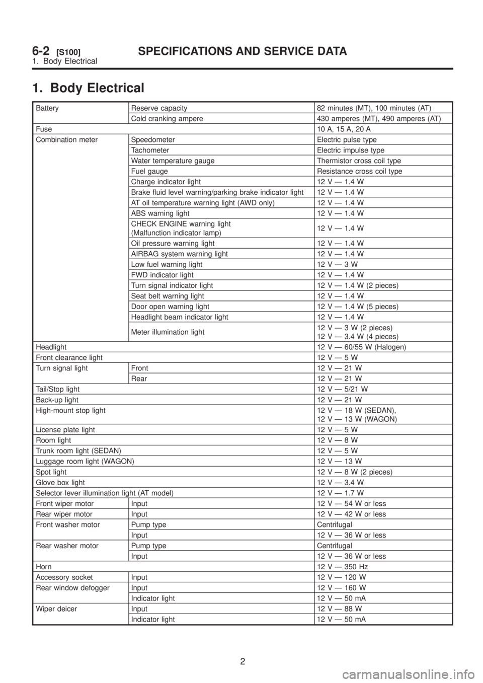
1. Body Electrical
Battery Reserve capacity 82 minutes (MT), 100 minutes (AT)
Cold cranking ampere 430 amperes (MT), 490 amperes (AT)
Fuse10 A, 15 A, 20 A
Combination meter Speedometer Electric pulse type
Tachometer Electric impulse type
Water temperature gauge Thermistor cross coil type
Fuel gauge Resistance cross coil type
Charge indicator light 12 V Ð 1.4 W
Brake fluid level warning/parking brake indicator light 12 V Ð 1.4 W
AT oil temperature warning light (AWD only) 12 V Ð 1.4 W
ABS warning light 12 V Ð 1.4 W
CHECK ENGINE warning light
(Malfunction indicator lamp)12 V Ð 1.4 W
Oil pressure warning light 12 V Ð 1.4 W
AIRBAG system warning light 12 V Ð 1.4 W
Low fuel warning light 12VÐ3W
FWD indicator light 12 V Ð 1.4 W
Turn signal indicator light 12 V Ð 1.4 W (2 pieces)
Seat belt warning light 12 V Ð 1.4 W
Door open warning light 12 V Ð 1.4 W (5 pieces)
Headlight beam indicator light 12 V Ð 1.4 W
Meter illumination light12VÐ3W(2pieces)
12 V Ð 3.4 W (4 pieces)
Headlight12 V Ð 60/55 W (Halogen)
Front clearance light 12VÐ5W
Turn signal light Front 12VÐ21W
Rear 12VÐ21W
Tail/Stop light12 V Ð 5/21 W
Back-up light12VÐ21W
High-mount stop light 12VÐ18W(SEDAN),
12VÐ13W(WAGON)
License plate light 12VÐ5W
Room light12VÐ8W
Trunk room light (SEDAN) 12VÐ5W
Luggage room light (WAGON) 12VÐ13W
Spot light12VÐ8W(2pieces)
Glove box light 12 V Ð 3.4 W
Selector lever illumination light (AT model) 12 V Ð 1.7 W
Front wiper motor Input 12VÐ54Worless
Rear wiper motor Input 12VÐ42Worless
Front washer motor Pump type Centrifugal
Input 12VÐ36Worless
Rear washer motor Pump type Centrifugal
Input 12VÐ36Worless
Horn12 V Ð 350 Hz
Accessory socket Input 12 V Ð 120 W
Rear window defogger Input 12 V Ð 160 W
Indicator light 12VÐ50mA
Wiper deicer Input 12VÐ88W
Indicator light 12VÐ50mA
2
6-2[S100]SPECIFICATIONS AND SERVICE DATA
1. Body Electrical
Page 1256 of 1456
B: BULB REPLACEMENT
B6M0761C
(1) Tachometer and temperature
gauge illumination
(2) Oil pressure
(3) CHECK ENGINE (Malfunction
Indicator Light)
(4) Tachometer illumination
(5) Turn signal (RH)
(6) Headlight beam(7) Door open (Front-Right)
(8) Seat belt
(9) Door open (Front-Left)
(10) Door open (Rear-Right)
(11) Door open (Rear-Left)
(12) Rear gate open (Wagon)
(13) Turn signal (LH)
(14) Speedometer illumination(15) Speedometer and fuel gauge
illumination
(16) Low fuel
(17) Charge
(18) Brake fluid level/parking brake
(19) FWD
(20) AT oil temperature
(21) ABS
28
6-2[W14B0]SERVICE PROCEDURE
14. Combination Meter
Page 1269 of 1456
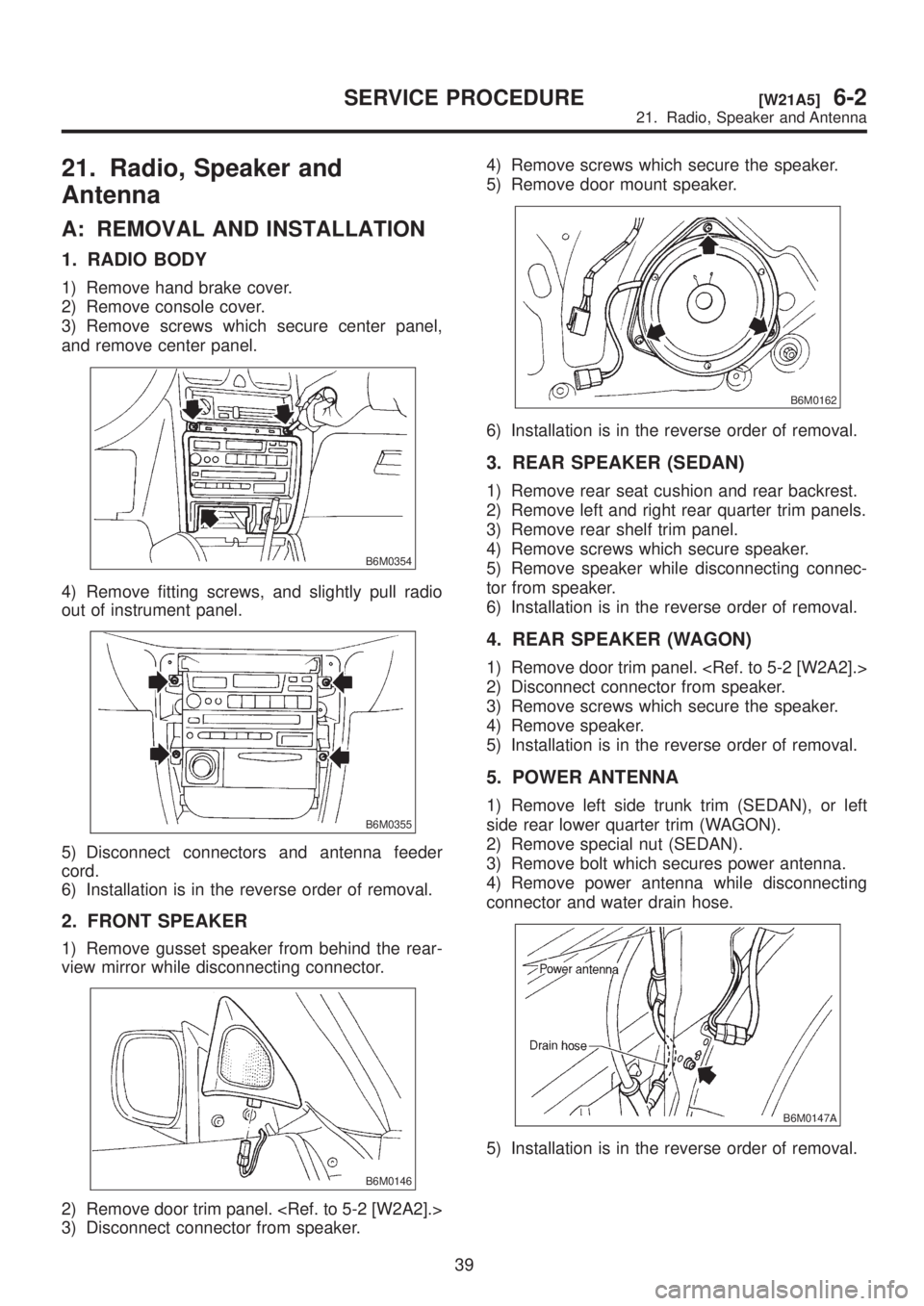
21. Radio, Speaker and
Antenna
A: REMOVAL AND INSTALLATION
1. RADIO BODY
1) Remove hand brake cover.
2) Remove console cover.
3) Remove screws which secure center panel,
and remove center panel.
B6M0354
4) Remove fitting screws, and slightly pull radio
out of instrument panel.
B6M0355
5) Disconnect connectors and antenna feeder
cord.
6) Installation is in the reverse order of removal.
2. FRONT SPEAKER
1) Remove gusset speaker from behind the rear-
view mirror while disconnecting connector.
B6M0146
2) Remove door trim panel.
3) Disconnect connector from speaker.4) Remove screws which secure the speaker.
5) Remove door mount speaker.
B6M0162
6) Installation is in the reverse order of removal.
3. REAR SPEAKER (SEDAN)
1) Remove rear seat cushion and rear backrest.
2) Remove left and right rear quarter trim panels.
3) Remove rear shelf trim panel.
4) Remove screws which secure speaker.
5) Remove speaker while disconnecting connec-
tor from speaker.
6) Installation is in the reverse order of removal.
4. REAR SPEAKER (WAGON)
1) Remove door trim panel.
2) Disconnect connector from speaker.
3) Remove screws which secure the speaker.
4) Remove speaker.
5) Installation is in the reverse order of removal.
5. POWER ANTENNA
1) Remove left side trunk trim (SEDAN), or left
side rear lower quarter trim (WAGON).
2) Remove special nut (SEDAN).
3) Remove bolt which secures power antenna.
4) Remove power antenna while disconnecting
connector and water drain hose.
B6M0147A
5) Installation is in the reverse order of removal.
39
[W21A5]6-2SERVICE PROCEDURE
21. Radio, Speaker and Antenna