Page 1215 of 1456
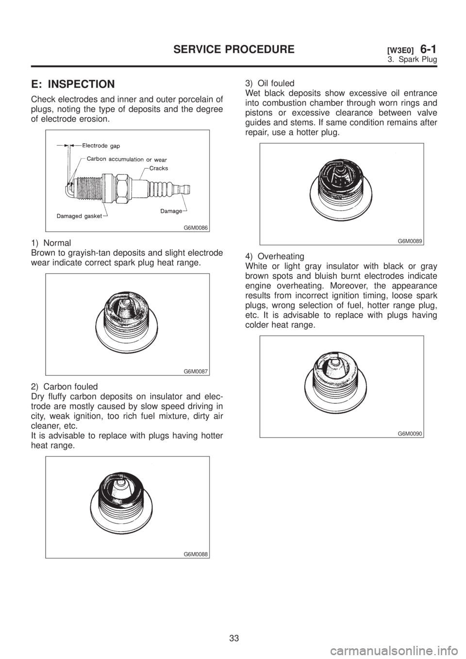
E: INSPECTION
Check electrodes and inner and outer porcelain of
plugs, noting the type of deposits and the degree
of electrode erosion.
G6M0086
1) Normal
Brown to grayish-tan deposits and slight electrode
wear indicate correct spark plug heat range.
G6M0087
2) Carbon fouled
Dry fluffy carbon deposits on insulator and elec-
trode are mostly caused by slow speed driving in
city, weak ignition, too rich fuel mixture, dirty air
cleaner, etc.
It is advisable to replace with plugs having hotter
heat range.
G6M0088
3) Oil fouled
Wet black deposits show excessive oil entrance
into combustion chamber through worn rings and
pistons or excessive clearance between valve
guides and stems. If same condition remains after
repair, use a hotter plug.
G6M0089
4) Overheating
White or light gray insulator with black or gray
brown spots and bluish burnt electrodes indicate
engine overheating. Moreover, the appearance
results from incorrect ignition timing, loose spark
plugs, wrong selection of fuel, hotter range plug,
etc. It is advisable to replace with plugs having
colder heat range.
G6M0090
33
[W3E0]6-1SERVICE PROCEDURE
3. Spark Plug
Page 1229 of 1456
any other metallic portion of the vehicle
because a short circuit will be caused.
1) External parts:
Check for the existence of dirt or cracks on the
battery case, top cover, vent plugs, and terminal
posts. If necessary, clean with water and wipe with
a dry cloth. Apply a thin coat of grease on the ter-
minal posts to prevent corrosion.
2) Electrolyte level:
Check the electrolyte level in each cell. If the level
is below MIN LEVEL, bring the level to MAX
LEVEL by pouring distilled water into the battery
cell. Do not fill beyond MAX LEVEL.
3) Specific gravity of electrolyte:
(1) Measure specific gravity of electrolyte using
a hydrometer and a thermometer.
Specific gravity varies with temperature of elec-
trolyte so that it must be corrected at 20ÉC
(68ÉF) using the following equation:
S
20= St + 0.0007 x (t þ 20)
S
20:Specific gravity corrected at electrolyte
temperature of 20ÉC (68ÉF)
St :Measured specific gravity
t:Measured temperature ÉC
Determine whether or not battery must be
charged, according to corrected specific
gravity.
Standard specific gravity:
1.220 Ð 1.290 [at 20ÉC (68ÉF)]
G6M0103
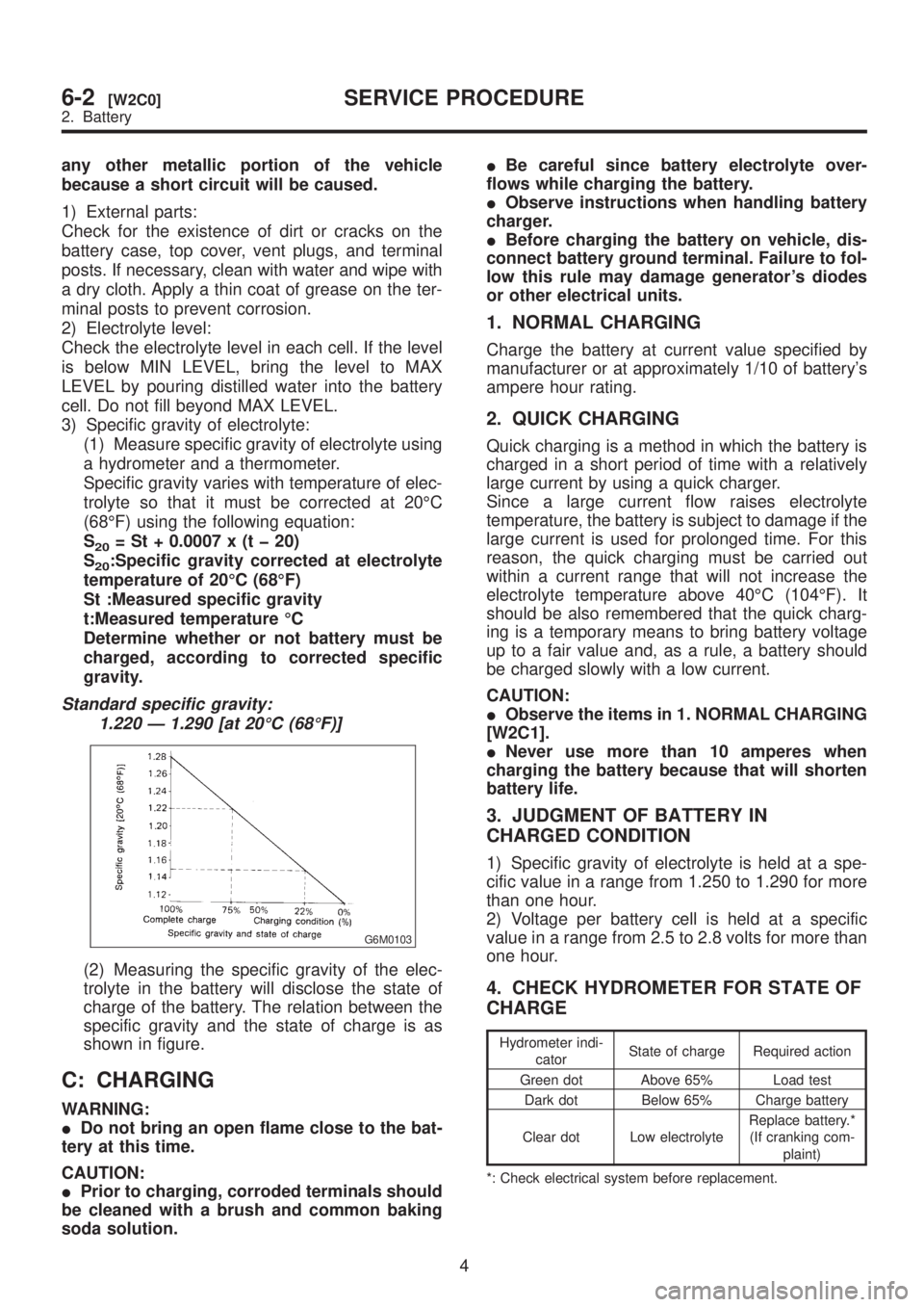
(2) Measuring the specific gravity of the elec-
trolyte in the battery will disclose the state of
charge of the battery. The relation between the
specific gravity and the state of charge is as
shown in figure.
C: CHARGING
WARNING:
IDo not bring an open flame close to the bat-
tery at this time.
CAUTION:
IPrior to charging, corroded terminals should
be cleaned with a brush and common baking
soda solution.IBe careful since battery electrolyte over-
flows while charging the battery.
IObserve instructions when handling battery
charger.
IBefore charging the battery on vehicle, dis-
connect battery ground terminal. Failure to fol-
low this rule may damage generator's diodes
or other electrical units.
1. NORMAL CHARGING
Charge the battery at current value specified by
manufacturer or at approximately 1/10 of battery's
ampere hour rating.
2. QUICK CHARGING
Quick charging is a method in which the battery is
charged in a short period of time with a relatively
large current by using a quick charger.
Since a large current flow raises electrolyte
temperature, the battery is subject to damage if the
large current is used for prolonged time. For this
reason, the quick charging must be carried out
within a current range that will not increase the
electrolyte temperature above 40ÉC (104ÉF). It
should be also remembered that the quick charg-
ing is a temporary means to bring battery voltage
up to a fair value and, as a rule, a battery should
be charged slowly with a low current.
CAUTION:
IObserve the items in 1. NORMAL CHARGING
[W2C1].
INever use more than 10 amperes when
charging the battery because that will shorten
battery life.
3. JUDGMENT OF BATTERY IN
CHARGED CONDITION
1) Specific gravity of electrolyte is held at a spe-
cific value in a range from 1.250 to 1.290 for more
than one hour.
2) Voltage per battery cell is held at a specific
value in a range from 2.5 to 2.8 volts for more than
one hour.
4. CHECK HYDROMETER FOR STATE OF
CHARGE
Hydrometer indi-
catorState of charge Required action
Green dot Above 65% Load test
Dark dot Below 65% Charge battery
Clear dot Low electrolyteReplace battery.*
(If cranking com-
plaint)
*: Check electrical system before replacement.
4
6-2[W2C0]SERVICE PROCEDURE
2. Battery
Page 1291 of 1456
F: CONNECTOR SKETCH
IEach connector sketch clearly identifies the
shape and color of a connector as well as terminal
locations. Non-colored connectors are indicated in
natural color.
IWhen more than two types of connector number
are indicated in a connector sketch, it means that
the same type connectors are used.
G: GROUND
Each grounding point can be located easily by
referring to the corresponding wiring harness.
H: DIODE
A symbol is used to indicate a diode.
I: WIRE TRACING ON EXTENDED
WIRING DIAGRAMS
For a wiring diagram extending over at least two
pages, a symbol (consisting of the same charac-
ters with arrows), as shown below, facilitates wire
tracing from one page to the next.
A¨A, B¨B
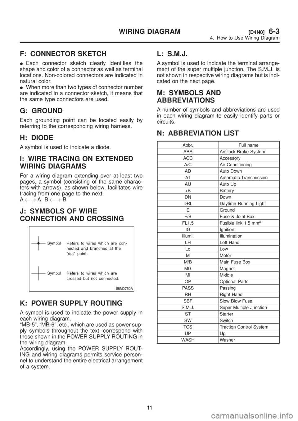
J: SYMBOLS OF WIRE
CONNECTION AND CROSSING
B6M0750A
K: POWER SUPPLY ROUTING
A symbol is used to indicate the power supply in
each wiring diagram.
ªMB-5º, ªMB-6º, etc., which are used as power sup-
ply symbols throughout the text, correspond with
those shown in the POWER SUPPLY ROUTING in
the wiring diagram.
Accordingly, using the POWER SUPPLY ROUT-
ING and wiring diagrams permits service person-
nel to understand the entire electrical arrangement
of a system.
L: S.M.J.
A symbol is used to indicate the terminal arrange-
ment of the super multiple junction. The S.M.J. is
not shown in respective wiring diagrams but is indi-
cated on the next page.
M: SYMBOLS AND
ABBREVIATIONS
A number of symbols and abbreviations are used
in each wiring diagram to easily identify parts or
circuits.
N: ABBREVIATION LIST
Abbr. Full name
ABS Antilock Brake System
ACC Accessory
A/C Air Conditioning
AD Auto Down
AT Automatic Transmission
AU Auto Up
+B Battery
DN Down
DRL Daytime Running Light
E Ground
F/B Fuse & Joint Box
FL1.5 Fusible link 1.5 mm
2
IG Ignition
Illumi. Illumination
LH Left Hand
Lo Low
M Motor
M/B Main Fuse Box
MG Magnet
Mi Middle
OP Optional Parts
PASS Passing
RH Right Hand
SBF Slow Blow Fuse
S.M.J. Super Multiple Junction
ST Starter
SW Switch
TCS Traction Control System
UP Up
WASH Washer
11
[D4N0]6-3WIRING DIAGRAM
4. How to Use Wiring Diagram
Page 1310 of 1456
D: AIR CONDITIONING SYSTEM
1. LHD MODEL
30
6-3[D6D1]WIRING DIAGRAM
6. Wiring Diagram
