Page 609 of 1456

7) Tighten bolts.
Tightening torque:
8
±1 N´m (0.8±0.1 kg-m, 5.8±0.7 ft-lb)
B3M1130A
(A) Short bolts
(B) Middle bolts
(C) Long bolt
(D) Reamer bolts
8) Install the sensor, solenoids and duty solenoid
S.
Tightening torque:
T: 8
±1 N´m (0.8±0.1 kg-m, 5.8±0.7 ft-lb)
B3M1039B
(A) Lock-up duty solenoid (Blue)
(B) Low clutch timing solenoid (Gray)
(C) Line pressure duty solenoid (Red)
(D) Shift solenoid 1 (Yellow)
(E) Shift solenoid 2 (Green)
(F) 2-4 brake timing solenoid (Black)
(G) 2-4 brake duty solenoid D (Red)
(H) ATF temperature sensor
9) Install oil strainer to lower valve body.
Tightening torque:
8
±1 N´m (0.8±0.1 kg-m, 5.8±0.7 ft-lb)
15. Oil Pump Assembly
A: DISASSEMBLY
1) Remove the oil seal retainer.
Also remove the O-ring and oil seal (air breather).
B3M1094A
2) Remove O-rings from oil pump housing.
CAUTION:
Be careful not to damage O-ring.
3) Remove four seal rings.
CAUTION:
Be careful not to damage O-ring.
B3M1095A
4) Remove the oil pump cover.
NOTE:
Lightly tap the end of the stator shaft to remove the
cover.
B3M1139A
80
3-2[W15A0]SERVICE PROCEDURE
15. Oil Pump Assembly
Page 610 of 1456

7) Tighten bolts.
Tightening torque:
8
±1 N´m (0.8±0.1 kg-m, 5.8±0.7 ft-lb)
B3M1130A
(A) Short bolts
(B) Middle bolts
(C) Long bolt
(D) Reamer bolts
8) Install the sensor, solenoids and duty solenoid
S.
Tightening torque:
T: 8
±1 N´m (0.8±0.1 kg-m, 5.8±0.7 ft-lb)
B3M1039B
(A) Lock-up duty solenoid (Blue)
(B) Low clutch timing solenoid (Gray)
(C) Line pressure duty solenoid (Red)
(D) Shift solenoid 1 (Yellow)
(E) Shift solenoid 2 (Green)
(F) 2-4 brake timing solenoid (Black)
(G) 2-4 brake duty solenoid D (Red)
(H) ATF temperature sensor
9) Install oil strainer to lower valve body.
Tightening torque:
8
±1 N´m (0.8±0.1 kg-m, 5.8±0.7 ft-lb)
15. Oil Pump Assembly
A: DISASSEMBLY
1) Remove the oil seal retainer.
Also remove the O-ring and oil seal (air breather).
B3M1094A
2) Remove O-rings from oil pump housing.
CAUTION:
Be careful not to damage O-ring.
3) Remove four seal rings.
CAUTION:
Be careful not to damage O-ring.
B3M1095A
4) Remove the oil pump cover.
NOTE:
Lightly tap the end of the stator shaft to remove the
cover.
B3M1139A
80
3-2[W15A0]SERVICE PROCEDURE
15. Oil Pump Assembly
Page 641 of 1456
2. Automatic Transmission
S3M0015A
(1) Button A
(2) Button B
(3) Spring (button)
(4) Grip
(5) Indicator cover
(6) Selector lever lower
(7) Pin
(8) Packing
(9) Plate
(10) Detent spring(11) Selector lever upper
(12) Rod
(13) Indicator light bulb
(14) Retainer spring
(15) Snap pin
(16) Outer cable
(17) Inner cable
(18) Nut (front)
(19) Nut (rear)
(20) Lock plate(21) Shift-lock solenoid
(22) Lock arm
(23) ªPº position switch
Tightening torque: N´m (kg-m, ft-lb)
T1:
5.9±1.5 (0.6±0.15, 4.3±1.1)
T2:12±3 (1.2±0.3, 8.7±2.2)
T3:25±7 (2.5±0.7, 18.1±5.1)
4
3-3[C200]COMPONENT PARTS
2. Automatic Transmission
Page 647 of 1456
![SUBARU LEGACY 1999 Service Repair Manual 2) Remove console box. <Ref. to 5-4 [W1A0].>
3) Disconnect the connectors, then remove the six
screws to take out the selector lever assembly
from the body.
S3M0017A
B: DISASSEMBLY
1) Remove connector SUBARU LEGACY 1999 Service Repair Manual 2) Remove console box. <Ref. to 5-4 [W1A0].>
3) Disconnect the connectors, then remove the six
screws to take out the selector lever assembly
from the body.
S3M0017A
B: DISASSEMBLY
1) Remove connector](/manual-img/17/57435/w960_57435-646.png)
2) Remove console box.
3) Disconnect the connectors, then remove the six
screws to take out the selector lever assembly
from the body.
S3M0017A
B: DISASSEMBLY
1) Remove connector from plate.
B3M0645
2) Remove indicator light and two screws.
3) Remove retainer spring, then pull up selector
lever grip with indicator cover for holding selector
lever button.
CAUTION:
Pull the selector lever grip carefully so that the
selector lever button may not jump out.
B3M0646A
4) Remove shift-lock solenoid and ªPº position
switch.
S3M0018A
5) Remove cap and clip, then extract pin.
6) Remove selector lever lower then take away
selector lever upper from plate.
B3M0647A
C: INSPECTION
1) Inspect removed parts by comparing with new
ones for deformation, damage and wear. Correct
or replace if defective.
2) Confirm the following parts for operating condi-
tion before assembly.
(1) Sliding condition of the button in the grip ...
it should move smoothly.
(2) Insertion of the grip on the selector lever ...
when pushing the grip on the selector lever by
hand, screw holes should be aligned.
(3) Operation of selector lever and rod ... they
should move smoothly.
D: ASSEMBLY
1) Clean all parts before assembly.
2) Apply grease [NIGTIGHT LYW No. 2 or equiva-
lent] to each parts.
3) Assembly is in the reverse order of disassem-
bly.
4) After completion of fitting, transfer selector
lever to range ªPº Ð ª1º, pressing the button of the
grip; then check whether the indicator and selector
lever agree, whether the pointer and position mark
agree and what the operating force is.
9
[W2D0]3-3SERVICE PROCEDURE
2. Automatic Transmission
Page 648 of 1456

E: INSTALLATION
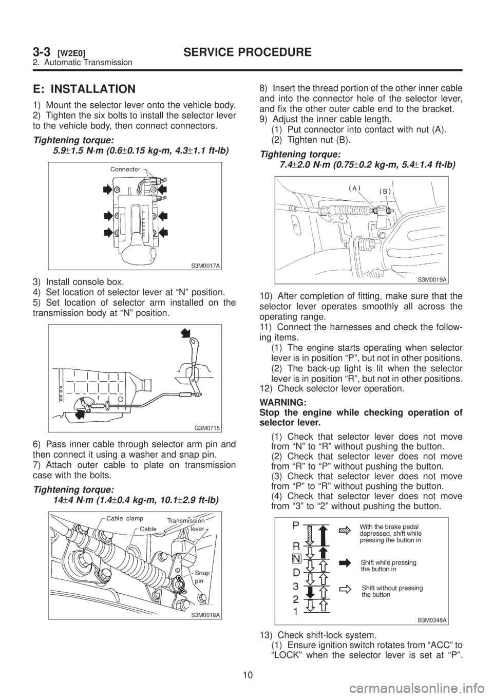
1) Mount the selector lever onto the vehicle body.
2) Tighten the six bolts to install the selector lever
to the vehicle body, then connect connectors.
Tightening torque:
5.9
±1.5 N´m (0.6±0.15 kg-m, 4.3±1.1 ft-lb)
S3M0017A
3) Install console box.
4) Set location of selector lever at ªNº position.
5) Set location of selector arm installed on the
transmission body at ªNº position.
G3M0715
6) Pass inner cable through selector arm pin and
then connect it using a washer and snap pin.
7) Attach outer cable to plate on transmission
case with the bolts.
Tightening torque:
14
±4 N´m (1.4±0.4 kg-m, 10.1±2.9 ft-lb)
S3M0016A
8) Insert the thread portion of the other inner cable
and into the connector hole of the selector lever,
and fix the other outer cable end to the bracket.
9) Adjust the inner cable length.
(1) Put connector into contact with nut (A).
(2) Tighten nut (B).
Tightening torque:
7.4
±2.0 N´m (0.75±0.2 kg-m, 5.4±1.4 ft-lb)
S3M0019A
10) After completion of fitting, make sure that the
selector lever operates smoothly all across the
operating range.
11) Connect the harnesses and check the follow-
ing items.
(1) The engine starts operating when selector
lever is in position ªPº, but not in other positions.
(2) The back-up light is lit when the selector
lever is in position ªRº, but not in other positions.
12) Check selector lever operation.
WARNING:
Stop the engine while checking operation of
selector lever.
(1) Check that selector lever does not move
from ªNº to ªRº without pushing the button.
(2) Check that selector lever does not move
from ªRº to ªPº without pushing the button.
(3) Check that selector lever does not move
from ªPº to ªRº without pushing the button.
(4) Check that selector lever does not move
from ª3º to ª2º without pushing the button.
B3M0348A
13) Check shift-lock system.
(1) Ensure ignition switch rotates from ªACCº to
ªLOCKº when the selector lever is set at ªPº.
10
3-3[W2E0]SERVICE PROCEDURE
2. Automatic Transmission
Page 680 of 1456

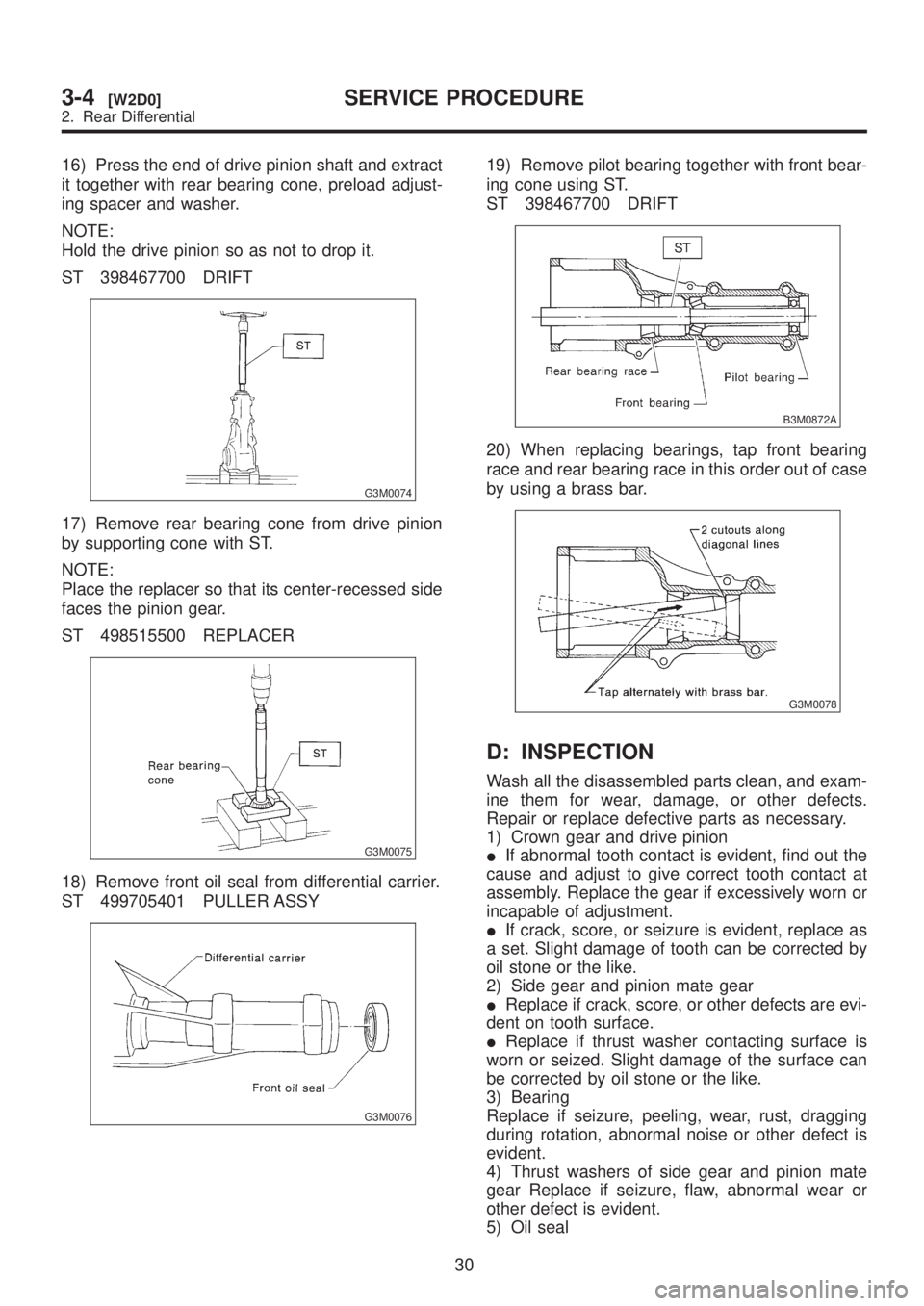
16) Press the end of drive pinion shaft and extract
it together with rear bearing cone, preload adjust-
ing spacer and washer.
NOTE:
Hold the drive pinion so as not to drop it.
ST 398467700 DRIFT
G3M0074
17) Remove rear bearing cone from drive pinion
by supporting cone with ST.
NOTE:
Place the replacer so that its center-recessed side
faces the pinion gear.
ST 498515500 REPLACER
G3M0075
18) Remove front oil seal from differential carrier.
ST 499705401 PULLER ASSY
G3M0076
19) Remove pilot bearing together with front bear-
ing cone using ST.
ST 398467700 DRIFT
B3M0872A
20) When replacing bearings, tap front bearing
race and rear bearing race in this order out of case
by using a brass bar.
G3M0078
D: INSPECTION
Wash all the disassembled parts clean, and exam-
ine them for wear, damage, or other defects.
Repair or replace defective parts as necessary.
1) Crown gear and drive pinion
IIf abnormal tooth contact is evident, find out the
cause and adjust to give correct tooth contact at
assembly. Replace the gear if excessively worn or
incapable of adjustment.
IIf crack, score, or seizure is evident, replace as
a set. Slight damage of tooth can be corrected by
oil stone or the like.
2) Side gear and pinion mate gear
IReplace if crack, score, or other defects are evi-
dent on tooth surface.
IReplace if thrust washer contacting surface is
worn or seized. Slight damage of the surface can
be corrected by oil stone or the like.
3) Bearing
Replace if seizure, peeling, wear, rust, dragging
during rotation, abnormal noise or other defect is
evident.
4) Thrust washers of side gear and pinion mate
gear Replace if seizure, flaw, abnormal wear or
other defect is evident.
5) Oil seal
30
3-4[W2D0]SERVICE PROCEDURE
2. Rear Differential
Page 688 of 1456

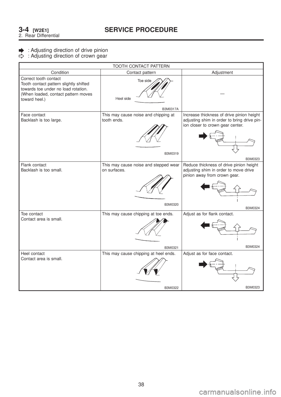
: Adjusting direction of drive pinion
: Adjusting direction of crown gear
TOOTH CONTACT PATTERN
Condition Contact pattern Adjustment
Correct tooth contact
Tooth contact pattern slightly shifted
towards toe under no load rotation.
(When loaded, contact pattern moves
toward heel.)
B3M0317A
Ð
Face contact
Backlash is too large.This may cause noise and chipping at
tooth ends.
B3M0319
Increase thickness of drive pinion height
adjusting shim in order to bring drive pin-
ion closer to crown gear center.
B3M0323
Flank contact
Backlash is too small.This may cause noise and stepped wear
on surfaces.
B3M0320
Reduce thickness of drive pinion height
adjusting shim in order to move drive
pinion away from crown gear.
B3M0324
Toe contact
Contact area is small.This may cause chipping at toe ends.
B3M0321
Adjust as for flank contact.
B3M0324
Heel contact
Contact area is small.This may cause chipping at heel ends.
B3M0322
Adjust as for face contact.
B3M0323
38
3-4[W2E1]SERVICE PROCEDURE
2. Rear Differential
Page 694 of 1456

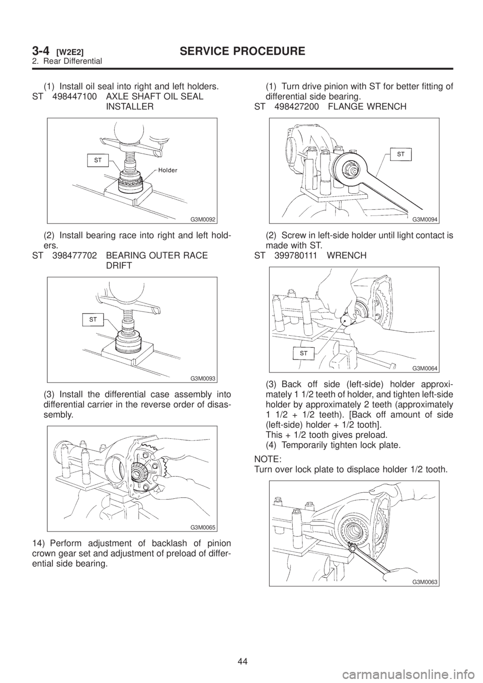
(1) Install oil seal into right and left holders.
ST 498447100 AXLE SHAFT OIL SEAL
INSTALLER
G3M0092
(2) Install bearing race into right and left hold-
ers.
ST 398477702 BEARING OUTER RACE
DRIFT
G3M0093
(3) Install the differential case assembly into
differential carrier in the reverse order of disas-
sembly.
G3M0065
14) Perform adjustment of backlash of pinion
crown gear set and adjustment of preload of differ-
ential side bearing.(1) Turn drive pinion with ST for better fitting of
differential side bearing.
ST 498427200 FLANGE WRENCH
G3M0094
(2) Screw in left-side holder until light contact is
made with ST.
ST 399780111 WRENCH
G3M0064
(3) Back off side (left-side) holder approxi-
mately 1 1/2 teeth of holder, and tighten left-side
holder by approximately 2 teeth (approximately
1 1/2 + 1/2 teeth). [Back off amount of side
(left-side) holder + 1/2 tooth].
This + 1/2 tooth gives preload.
(4) Temporarily tighten lock plate.
NOTE:
Turn over lock plate to displace holder 1/2 tooth.
G3M0063
44
3-4[W2E2]SERVICE PROCEDURE
2. Rear Differential