1999 SUBARU LEGACY light
[x] Cancel search: lightPage 697 of 1456

Adjusting direction of drive pinion
Adjusting direction of crown gear
TOOTH CONTACT PATTERN
Condition Contact pattern Adjustment
Correct tooth contact
Tooth contact pattern slightly shifted
towards toe under no load rotation.
(When loaded, contact pattern
moves toward heel.)
G3M0098A
Ð
Face contact
Backlash is too large.This may cause noise and chipping at
tooth ends.
G3M0098B
Increase thickness of drive pinion height
adjusting washer in order to bring drive
pinion closer to crown gear center.
G3M0098F
Flank contact
Backlash is too small.This may cause noise and stepped wear
on surfaces.
G3M0098C
Reduce thickness of drive pinion height
adjusting washer in order to move drive
pinion away from crown gear.
G3M0098G
Toe contact Contact area is small.
This may cause chipping at toe ends.
G3M0098D
Adjust as for flank contact.
G3M0098G
Heel contact Contact area is small.
This may cause chipping at heel ends.
G3M0098E
Adjust as for face contact
G3M0098F
F: INSTALLATION
To install, reverse the removal sequence.
1) Install the air breather cap tapping with a plas-
tic hammer.CAUTION:
Be sure to install new air breather cap.
2) Position front member on body by passing it
under parking brake cable and securing to rear
differential.
47
[W2F0]3-4SERVICE PROCEDURE
2. Rear Differential
Page 745 of 1456
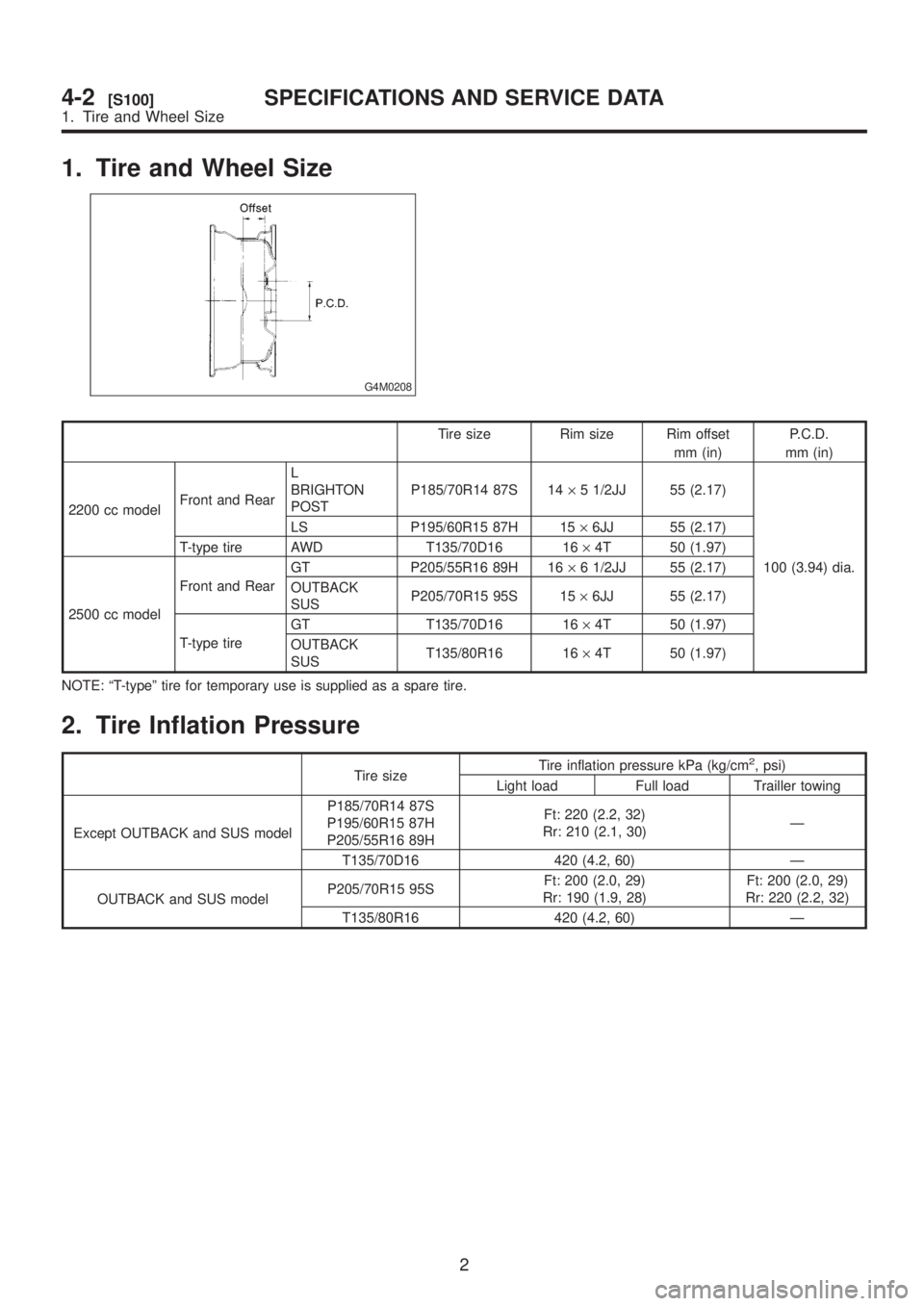
1. Tire and Wheel Size
G4M0208
Tire size Rim size Rim offset
mm (in)P.C.D.
mm (in)
2200 cc modelFront and RearL
BRIGHTON
POSTP185/70R14 87S 14´5 1/2JJ 55 (2.17)
100 (3.94) dia. LS P195/60R15 87H 15´6JJ 55 (2.17)
T-type tire AWD T135/70D16 16´4T 50 (1.97)
2500 cc modelFront and RearGT P205/55R16 89H 16´6 1/2JJ 55 (2.17)
OUTBACK
SUSP205/70R15 95S 15´6JJ 55 (2.17)
T-type tireGT T135/70D16 16´4T 50 (1.97)
OUTBACK
SUST135/80R16 16´4T 50 (1.97)
NOTE: ªT-typeº tire for temporary use is supplied as a spare tire.
2. Tire Inflation Pressure
Tire sizeTire inflation pressure kPa (kg/cm
2, psi)
Light load Full load Trailler towing
Except OUTBACK and SUS modelP185/70R14 87S
P195/60R15 87H
P205/55R16 89HFt: 220 (2.2, 32)
Rr: 210 (2.1, 30)Ð
T135/70D16 420 (4.2, 60) Ð
OUTBACK and SUS modelP205/70R15 95SFt: 200 (2.0, 29)
Rr: 190 (1.9, 28)Ft: 200 (2.0, 29)
Rr: 220 (2.2, 32)
T135/80R16 420 (4.2, 60) Ð
2
4-2[S100]SPECIFICATIONS AND SERVICE DATA
1. Tire and Wheel Size
Page 746 of 1456
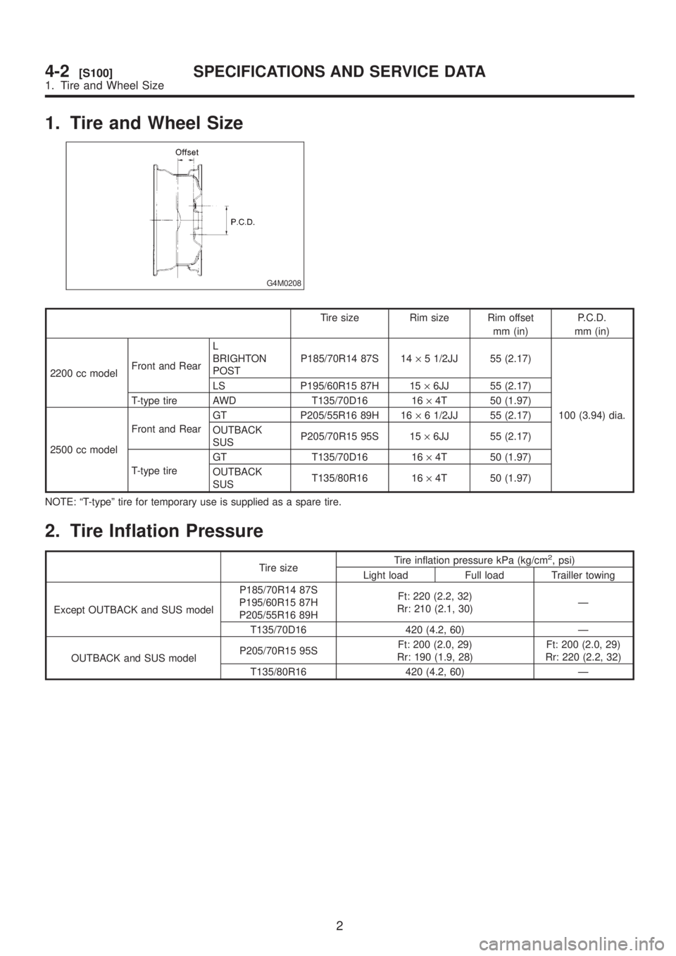
1. Tire and Wheel Size
G4M0208
Tire size Rim size Rim offset
mm (in)P.C.D.
mm (in)
2200 cc modelFront and RearL
BRIGHTON
POSTP185/70R14 87S 14´5 1/2JJ 55 (2.17)
100 (3.94) dia. LS P195/60R15 87H 15´6JJ 55 (2.17)
T-type tire AWD T135/70D16 16´4T 50 (1.97)
2500 cc modelFront and RearGT P205/55R16 89H 16´6 1/2JJ 55 (2.17)
OUTBACK
SUSP205/70R15 95S 15´6JJ 55 (2.17)
T-type tireGT T135/70D16 16´4T 50 (1.97)
OUTBACK
SUST135/80R16 16´4T 50 (1.97)
NOTE: ªT-typeº tire for temporary use is supplied as a spare tire.
2. Tire Inflation Pressure
Tire sizeTire inflation pressure kPa (kg/cm
2, psi)
Light load Full load Trailler towing
Except OUTBACK and SUS modelP185/70R14 87S
P195/60R15 87H
P205/55R16 89HFt: 220 (2.2, 32)
Rr: 210 (2.1, 30)Ð
T135/70D16 420 (4.2, 60) Ð
OUTBACK and SUS modelP205/70R15 95SFt: 200 (2.0, 29)
Rr: 190 (1.9, 28)Ft: 200 (2.0, 29)
Rr: 220 (2.2, 32)
T135/80R16 420 (4.2, 60) Ð
2
4-2[S100]SPECIFICATIONS AND SERVICE DATA
1. Tire and Wheel Size
Page 775 of 1456
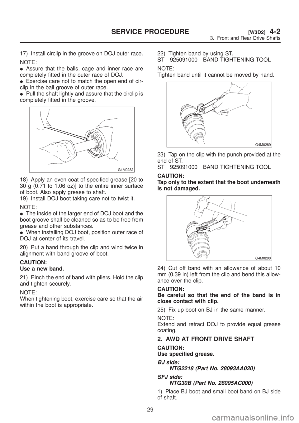
17) Install circlip in the groove on DOJ outer race.
NOTE:
IAssure that the balls, cage and inner race are
completely fitted in the outer race of DOJ.
IExercise care not to match the open end of cir-
clip in the ball groove of outer race.
IPull the shaft lightly and assure that the circlip is
completely fitted in the groove.
G4M0282
18) Apply an even coat of specified grease [20 to
30 g (0.71 to 1.06 oz)] to the entire inner surface
of boot. Also apply grease to shaft.
19) Install DOJ boot taking care not to twist it.
NOTE:
IThe inside of the larger end of DOJ boot and the
boot groove shall be cleaned so as to be free from
grease and other substances.
IWhen installing DOJ boot, position outer race of
DOJ at center of its travel.
20) Put a band through the clip and wind twice in
alignment with band groove of boot.
CAUTION:
Use a new band.
21) Pinch the end of band with pliers. Hold the clip
and tighten securely.
NOTE:
When tightening boot, exercise care so that the air
within the boot is appropriate.22) Tighten band by using ST.
ST 925091000 BAND TIGHTENING TOOL
NOTE:
Tighten band until it cannot be moved by hand.
G4M0289
23) Tap on the clip with the punch provided at the
end of ST.
ST 925091000 BAND TIGHTENING TOOL
CAUTION:
Tap only to the extent that the boot underneath
is not damaged.
G4M0290
24) Cut off band with an allowance of about 10
mm (0.39 in) left from the clip and bend this allow-
ance over the clip.
CAUTION:
Be careful so that the end of the band is in
close contact with clip.
25) Fix up boot on BJ in the same manner.
NOTE:
Extend and retract DOJ to provide equal grease
coating.
2. AWD AT FRONT DRIVE SHAFT
CAUTION:
Use specified grease.
BJ side:
NTG2218 (Part No. 28093AA020)
SFJ side:
NTG30B (Part No. 28095AC000)
1) Place BJ boot and small boot band on BJ side
of shaft.
29
[W3D2]4-2SERVICE PROCEDURE
3. Front and Rear Drive Shafts
Page 777 of 1456

14) Align alignment marks on free ring and trun-
nion and install free ring.
B4M0777
15) Align alignment marks on shaft and outer
race, and install outer race.
B4M0774
16) Install circlip in the groove on SFJ outer race.
CAUTION:
Pull the shaft lightly and assure that the circlip
is completely fitted in the groove.
17) Apply an even coat of the specified grease 30
to 40 g (1.06 to 1.41 oz) to the entire inner surface
of boot.
18) Install SFJ boot taking care not to twist it.
CAUTION:
IThe inside of the larger end of SFJ boot and
the boot groove shall be cleaned so as to be
free from grease and other substances.
IWhen installing SFJ boot, position outer
race of SFJ at center of its travel.
19) Put a band through the clip and wind twice in
alignment with band groove of boot.CAUTION:
Use a new band.
20) Pinch the end of band with pliers. Hold the clip
and tighten securely.
NOTE:
When tightening boot, exercise care so that the air
within the boot is appropriate.
21) Tighten band by using ST.
ST 925091000 BAND TIGHTENING TOOL
NOTE:
Tighten band until it cannot be moved by hand.
G4M0289
22) Tap on the clip with the punch provided at the
end of ST.
ST 925091000 BAND TIGHTENING TOOL
CAUTION:
Tap to an extent that the boot underneath is not
damaged.
G4M0290
23) Cut off band with an allowance of about 10
mm (0.39 in) left from the clip and bend this allow-
ance over the clip.
CAUTION:
Be careful so that the end of the band is in
close contact with clip.
24) Fix up boot on BJ in the same manner.
NOTE:
Extend and retract SFJ to provide equal grease
coating.
31
[W3D2]4-2SERVICE PROCEDURE
3. Front and Rear Drive Shafts
Page 778 of 1456

3. REAR DRIVE SHAFT
CAUTION:
Use specified grease.
BJ side:
Molylex No. 2 (Part No. 723223010) or
Sunlight TB2-A
DOJ side:
VU-3A702 (Yellow) (Part No. 23223GA050)
1) Install BJ boot in specified position, and fill it
with 60 to 70 g (2.12 to 2.47 oz) of specified
grease.
2) Place DOJ boot at the center of shaft.
CAUTION:
Be sure to wrap shaft splines with vinyl tape to
prevent boot from scratches.
3) Insert DOJ cage onto shaft.
NOTE:
Insert the cage with the cut-out portion facing the
shaft end, since the cage has an orientation.
G4M0284
4) Install DOJ inner race on shaft and fit snap ring
with pliers.
NOTE:
Confirm that the snap ring is completely fitted in the
shaft groove.
G4M0285
5) Install cage, which was previously fitted, to
inner race fixed upon shaft.
NOTE:
Fit the cage with the protruded part aligned with the
track on the inner race and then turn by a half
pitch.
B4M0228C
6) Fill 80 to 90 g (2.82 to 3.17 oz) of specified
grease into the interior of DOJ outer race.
7) Apply a coat of specified grease to the cage
pocket and six balls.
8) Insert six balls into the cage pocket.
9) Align the outer race track and ball positions and
place in the part where shaft, inner race, cage and
balls are previously installed, and then fit outer
race.
B4M0227C
32
4-2[W3D3]SERVICE PROCEDURE
3. Front and Rear Drive Shafts
Page 779 of 1456
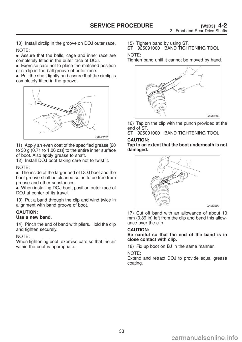
10) Install circlip in the groove on DOJ outer race.
NOTE:
IAssure that the balls, cage and inner race are
completely fitted in the outer race of DOJ.
IExercise care not to place the matched position
of circlip in the ball groove of outer race.
IPull the shaft lightly and assure that the circlip is
completely fitted in the groove.
G4M0282
11) Apply an even coat of the specified grease [20
to 30 g (0.71 to 1.06 oz)] to the entire inner surface
of boot. Also apply grease to shaft.
12) Install DOJ boot taking care not to twist it.
NOTE:
IThe inside of the larger end of DOJ boot and the
boot groove shall be cleaned so as to be free from
grease and other substances.
IWhen installing DOJ boot, position outer race of
DOJ at center of its travel.
13) Put a band through the clip and wind twice in
alignment with band groove of boot.
CAUTION:
Use a new band.
14) Pinch the end of band with pliers. Hold the clip
and tighten securely.
NOTE:
When tightening boot, exercise care so that the air
within the boot is appropriate.15) Tighten band by using ST.
ST 925091000 BAND TIGHTENING TOOL
NOTE:
Tighten band until it cannot be moved by hand.
G4M0289
16) Tap on the clip with the punch provided at the
end of ST.
ST 925091000 BAND TIGHTENING TOOL
CAUTION:
Tap to an extent that the boot underneath is not
damaged.
G4M0290
17) Cut off band with an allowance of about 10
mm (0.39 in) left from the clip and bend this allow-
ance over the clip.
CAUTION:
Be careful so that the end of the band is in
close contact with clip.
18) Fix up boot on BJ in the same manner.
NOTE:
Extend and retract DOJ to provide equal grease
coating.
33
[W3D3]4-2SERVICE PROCEDURE
3. Front and Rear Drive Shafts
Page 853 of 1456
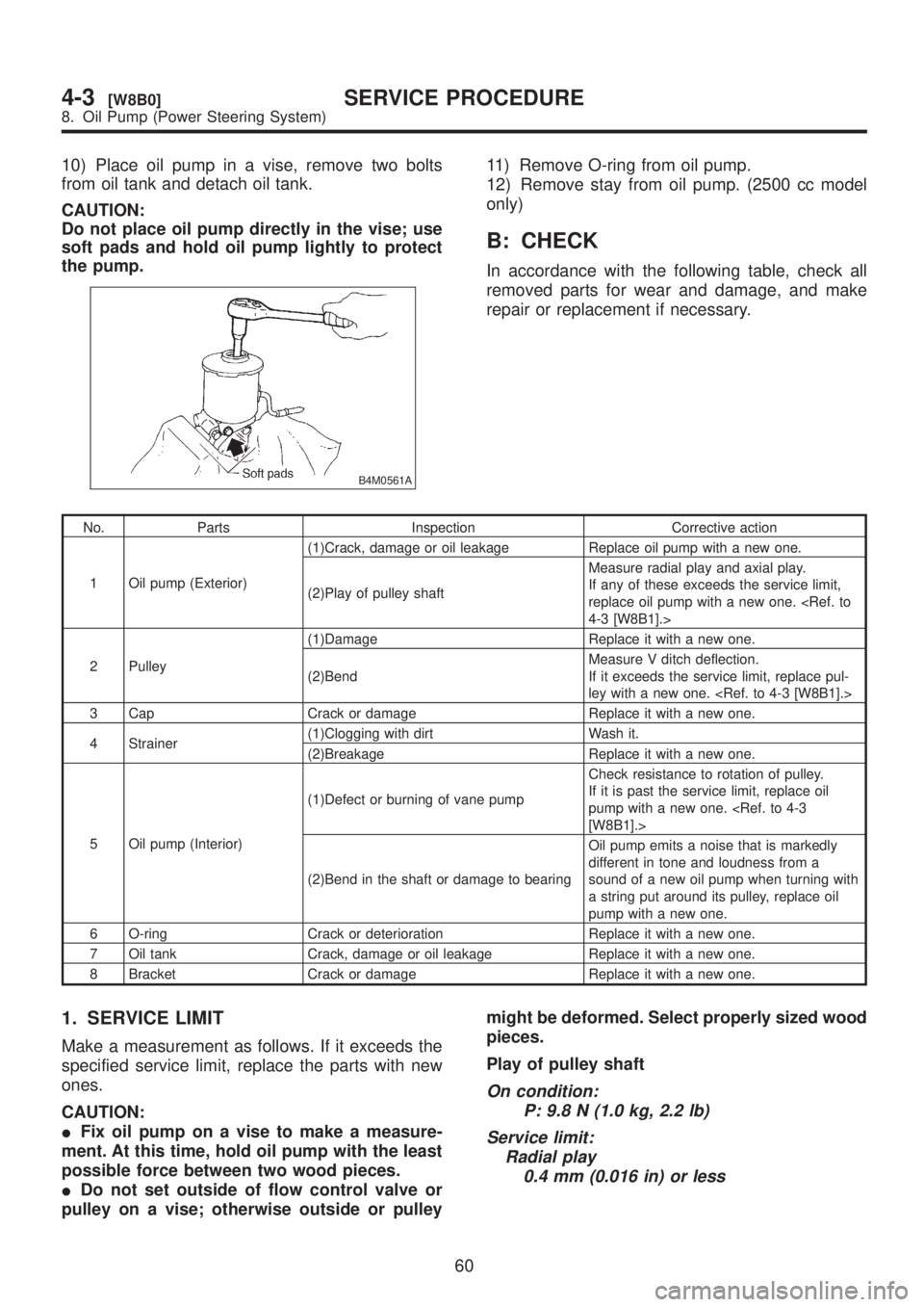
10) Place oil pump in a vise, remove two bolts
from oil tank and detach oil tank.
CAUTION:
Do not place oil pump directly in the vise; use
soft pads and hold oil pump lightly to protect
the pump.
B4M0561A
11) Remove O-ring from oil pump.
12) Remove stay from oil pump. (2500 cc model
only)
B: CHECK
In accordance with the following table, check all
removed parts for wear and damage, and make
repair or replacement if necessary.
No. Parts Inspection Corrective action
1 Oil pump (Exterior)(1)Crack, damage or oil leakage Replace oil pump with a new one.
(2)Play of pulley shaftMeasure radial play and axial play.
If any of these exceeds the service limit,
replace oil pump with a new one.
2 Pulley(1)Damage Replace it with a new one.
(2)BendMeasure V ditch deflection.
If it exceeds the service limit, replace pul-
ley with a new one.
3 Cap Crack or damage Replace it with a new one.
4 Strainer(1)Clogging with dirt Wash it.
(2)Breakage Replace it with a new one.
5 Oil pump (Interior)(1)Defect or burning of vane pumpCheck resistance to rotation of pulley.
If it is past the service limit, replace oil
pump with a new one.
(2)Bend in the shaft or damage to bearingOil pump emits a noise that is markedly
different in tone and loudness from a
sound of a new oil pump when turning with
a string put around its pulley, replace oil
pump with a new one.
6 O-ring Crack or deterioration Replace it with a new one.
7 Oil tank Crack, damage or oil leakage Replace it with a new one.
8 Bracket Crack or damage Replace it with a new one.
1. SERVICE LIMIT
Make a measurement as follows. If it exceeds the
specified service limit, replace the parts with new
ones.
CAUTION:
IFix oil pump on a vise to make a measure-
ment. At this time, hold oil pump with the least
possible force between two wood pieces.
IDo not set outside of flow control valve or
pulley on a vise; otherwise outside or pulleymight be deformed. Select properly sized wood
pieces.
Play of pulley shaft
On condition:
P: 9.8 N (1.0 kg, 2.2 lb)
Service limit:
Radial play
0.4 mm (0.016 in) or less
60
4-3[W8B0]SERVICE PROCEDURE
8. Oil Pump (Power Steering System)