Page 996 of 1456

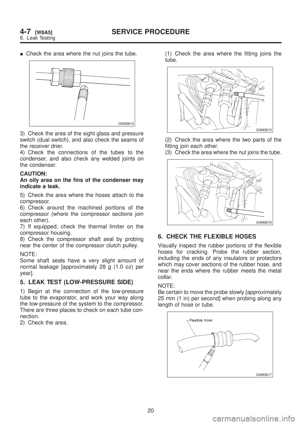
ICheck the area where the nut joins the tube.
G4M0614
3) Check the area of the sight glass and pressure
switch (dual switch), and also check the seams of
the receiver drier.
4) Check the connections of the tubes to the
condenser, and also check any welded joints on
the condenser.
CAUTION:
An oily area on the fins of the condenser may
indicate a leak.
5) Check the area where the hoses attach to the
compressor.
6) Check around the machined portions of the
compressor (where the compressor sections join
each other).
7) If equipped, check the thermal limiter on the
compressor housing.
8) Check the compressor shaft seal by probing
near the center of the compressor clutch pulley.
NOTE:
Some shaft seals have a very slight amount of
normal leakage [approximately 28 g (1.0 oz) per
year].
5. LEAK TEST (LOW-PRESSURE SIDE)
1) Begin at the connection of the low-pressure
tube to the evaporator, and work your way along
the low-pressure of the system to the compressor.
There are three places to check on each tube con-
nection.
2) Check the area.(1) Check the area where the fitting joins the
tube.
G4M0615
(2) Check the area where the two parts of the
fitting join each other.
(3) Check the area where the nut joins the tube.
G4M0616
6. CHECK THE FLEXIBLE HOSES
Visually inspect the rubber portions of the flexible
hoses for cracking. Probe the rubber section,
including the ends of any insulators or protectors
which may cover sections of the rubber hose, and
near the ends where the rubber meets the metal
collar.
NOTE:
Be certain to move the probe slowly [approximately
25 mm (1 in) per second] when probing along any
length of hose or tube.
G4M0617
20
4-7[W8A5]SERVICE PROCEDURE
8. Leak Testing
Page 1001 of 1456

11. Compressor
A: INSPECTION
1. COMPRESSOR CLUTCH
NOTE:
ICompressor is a swash plate type. When trouble
occurs, replace compressor as a single unit.
ICompressor clutch trouble is often caused by
clutch slippage and noise. Check and take correc-
tive measures, as required.
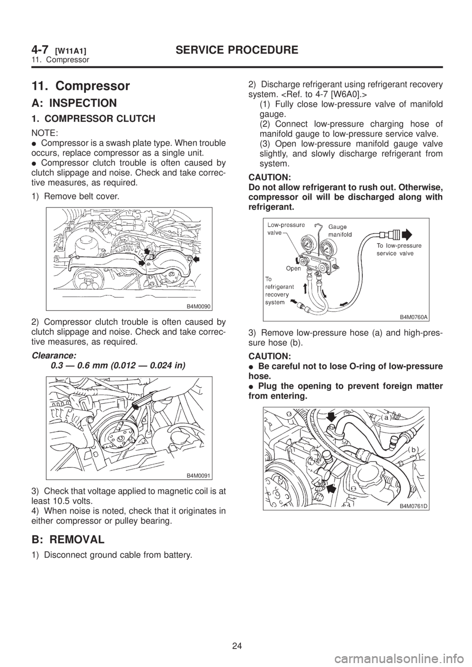
1) Remove belt cover.
B4M0090
2) Compressor clutch trouble is often caused by
clutch slippage and noise. Check and take correc-
tive measures, as required.
Clearance:
0.3 Ð 0.6 mm (0.012 Ð 0.024 in)
B4M0091
3) Check that voltage applied to magnetic coil is at
least 10.5 volts.
4) When noise is noted, check that it originates in
either compressor or pulley bearing.
B: REMOVAL
1) Disconnect ground cable from battery.2) Discharge refrigerant using refrigerant recovery
system.
(1) Fully close low-pressure valve of manifold
gauge.
(2) Connect low-pressure charging hose of
manifold gauge to low-pressure service valve.
(3) Open low-pressure manifold gauge valve
slightly, and slowly discharge refrigerant from
system.
CAUTION:
Do not allow refrigerant to rush out. Otherwise,
compressor oil will be discharged along with
refrigerant.
B4M0760A
3) Remove low-pressure hose (a) and high-pres-
sure hose (b).
CAUTION:
IBe careful not to lose O-ring of low-pressure
hose.
IPlug the opening to prevent foreign matter
from entering.
B4M0761D
24
4-7[W11A1]SERVICE PROCEDURE
11. Compressor
Page 1015 of 1456

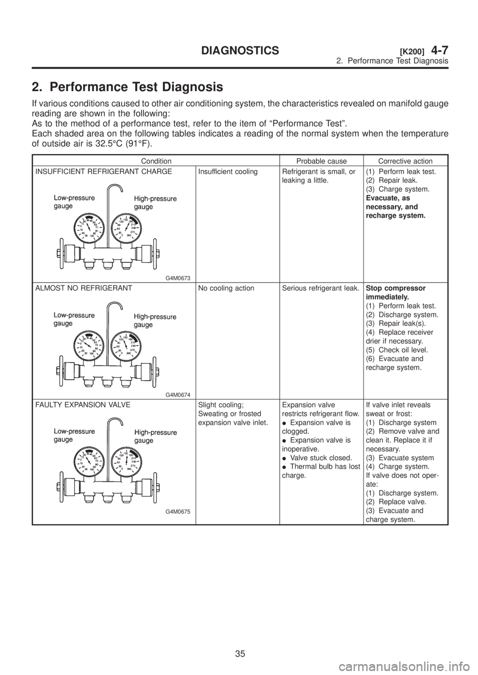
2. Performance Test Diagnosis
If various conditions caused to other air conditioning system, the characteristics revealed on manifold gauge
reading are shown in the following:
As to the method of a performance test, refer to the item of ªPerformance Testº.
Each shaded area on the following tables indicates a reading of the normal system when the temperature
of outside air is 32.5ÉC (91ÉF).
Condition Probable cause Corrective action
INSUFFICIENT REFRIGERANT CHARGE
G4M0673
Insufficient cooling Refrigerant is small, or
leaking a little.(1) Perform leak test.
(2) Repair leak.
(3) Charge system.
Evacuate, as
necessary, and
recharge system.
ALMOST NO REFRIGERANT
G4M0674
No cooling action Serious refrigerant leak.Stop compressor
immediately.
(1) Perform leak test.
(2) Discharge system.
(3) Repair leak(s).
(4) Replace receiver
drier if necessary.
(5) Check oil level.
(6) Evacuate and
recharge system.
FAULTY EXPANSION VALVE
G4M0675
Slight cooling;
Sweating or frosted
expansion valve inlet.Expansion valve
restricts refrigerant flow.
IExpansion valve is
clogged.
IExpansion valve is
inoperative.
IValve stuck closed.
IThermal bulb has lost
charge.If valve inlet reveals
sweat or frost:
(1) Discharge system
(2) Remove valve and
clean it. Replace it if
necessary.
(3) Evacuate system
(4) Charge system.
If valve does not oper-
ate:
(1) Discharge system.
(2) Replace valve.
(3) Evacuate and
charge system.
35
[K200]4-7DIAGNOSTICS
2. Performance Test Diagnosis
Page 1026 of 1456

2. Body Datum Points
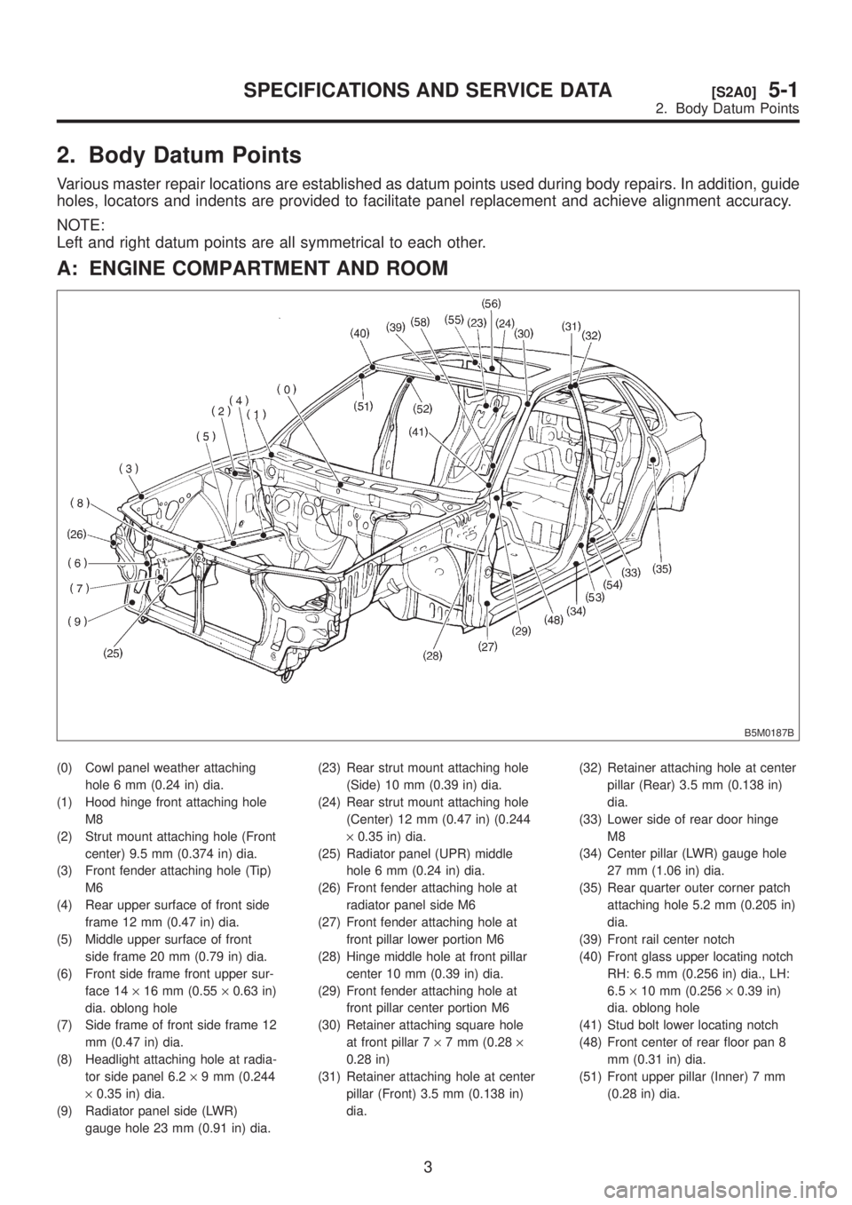
Various master repair locations are established as datum points used during body repairs. In addition, guide
holes, locators and indents are provided to facilitate panel replacement and achieve alignment accuracy.
NOTE:
Left and right datum points are all symmetrical to each other.
A: ENGINE COMPARTMENT AND ROOM
B5M0187B
(0) Cowl panel weather attaching
hole 6 mm (0.24 in) dia.
(1) Hood hinge front attaching hole
M8
(2) Strut mount attaching hole (Front
center) 9.5 mm (0.374 in) dia.
(3) Front fender attaching hole (Tip)
M6
(4) Rear upper surface of front side
frame 12 mm (0.47 in) dia.
(5) Middle upper surface of front
side frame 20 mm (0.79 in) dia.
(6) Front side frame front upper sur-
face 14´16 mm (0.55´0.63 in)
dia. oblong hole
(7) Side frame of front side frame 12
mm (0.47 in) dia.
(8) Headlight attaching hole at radia-
tor side panel 6.2´9 mm (0.244
´0.35 in) dia.
(9) Radiator panel side (LWR)
gauge hole 23 mm (0.91 in) dia.(23) Rear strut mount attaching hole
(Side) 10 mm (0.39 in) dia.
(24) Rear strut mount attaching hole
(Center) 12 mm (0.47 in) (0.244
´0.35 in) dia.
(25) Radiator panel (UPR) middle
hole 6 mm (0.24 in) dia.
(26) Front fender attaching hole at
radiator panel side M6
(27) Front fender attaching hole at
front pillar lower portion M6
(28) Hinge middle hole at front pillar
center 10 mm (0.39 in) dia.
(29) Front fender attaching hole at
front pillar center portion M6
(30) Retainer attaching square hole
at front pillar 7´7 mm (0.28´
0.28 in)
(31) Retainer attaching hole at center
pillar (Front) 3.5 mm (0.138 in)
dia.(32) Retainer attaching hole at center
pillar (Rear) 3.5 mm (0.138 in)
dia.
(33) Lower side of rear door hinge
M8
(34) Center pillar (LWR) gauge hole
27 mm (1.06 in) dia.
(35) Rear quarter outer corner patch
attaching hole 5.2 mm (0.205 in)
dia.
(39) Front rail center notch
(40) Front glass upper locating notch
RH: 6.5 mm (0.256 in) dia., LH:
6.5´10 mm (0.256´0.39 in)
dia. oblong hole
(41) Stud bolt lower locating notch
(48) Front center of rear floor pan 8
mm (0.31 in) dia.
(51) Front upper pillar (Inner) 7 mm
(0.28 in) dia.
3
[S2A0]5-1SPECIFICATIONS AND SERVICE DATA
2. Body Datum Points
Page 1027 of 1456
(52) Front seat belt adjust plate
attaching hole 12 mm (0.47 in)
dia.
(53) Rear door hinge middle hole 10
mm (0.39 in) dia.(54) Rear floor, near door 8 mm (0.31
in) dia.
(55) Trim upper attaching hole at 6
light 8 mm (0.31 in) dia.(56) Trim lower attaching hole at 6
light 8 mm (0.31 in) dia.
(58) Rear floor, near floor strut 15´
20 mm (0.59´0.79 in) dia.
oblong hole
4
5-1[S2A0]SPECIFICATIONS AND SERVICE DATA
2. Body Datum Points
Page 1028 of 1456
B: LUGGAGE COMPARTMENT AND ROOM
1. SEDAN
B5M0188B
(36) 6 light upper retainer attaching
square hole 7´7 mm (0.28´
0.28 in)
(42) Rear rail center notch
(43) Rear glass upper locating hole
RH: 6.5 mm (0.256 in) dia., LH:
6.5´10 mm (0.256´0.39 in)
dia. oblong hole
(44) Rear glass molding attaching
square hole 8´8 mm (0.31´
0.31 in)(45) Rear panel drain locater concave
part
(46) Front panel gauge hole 10 mm
(0.39 in) dia.
(47) Tunnel center M8
(59) Rear bumper attaching hole 45
mm (1.77 in) dia.
(65) Rear wiper attaching hole M6
(66) Trim attaching hole at rear skirt
(UPR) 7 mm (0.28 in) dia.(67) Rear bumper side attaching hole
6 mm (0.24 in) dia.
(68) Rear combination light mounting
hole 8 mm (0.31 in) dia.
(69) Rear bumper beam attaching
hole RH: 8 mm (0.31 in) dia.,
LH: 8´12 mm (0.31´0.47 in)
dia. oblong hole
5
[S2B1]5-1SPECIFICATIONS AND SERVICE DATA
2. Body Datum Points
Page 1029 of 1456
2. WAGON
B5M0189B
(37) D pillar cover attaching hole 12´
8 mm (0.47´0.31 in) dia.
(38) Shoulder mole attaching hole 8
mm (0.31 in) dia.
(49) Front pillar (LWR) gauge hole 10
mm (0.39 in) dia. (On both
Sedan and Wagon)
(50) Front pillar (UPR) gauge hole 16
mm (0.63 in) dia. (On both
Sedan and Wagon)(57) Retainer attaching square hole
at C pillar (UPR) 7´7 mm (0.28
´0.28 in)
(60) Trim attaching hole at rear skirt
(UPR) 15 mm (0.59 in) dia.
(61) Rear bumper side attaching hole
6 mm (0.24 in) dia.
(62) Rear seat belt bolt hole 13 mm
(0.51 in) dia.
(63) Rear rail locator concave part(64) Buffer attaching hole (UPR) M6
(70) Rear quarter end (LWR) gauge
hole 20 mm (0.79 in) dia.
(71) Rear combination light mounting
hole 7 mm (0.28 in) dia.
6
5-1[S2B2]SPECIFICATIONS AND SERVICE DATA
2. Body Datum Points
Page 1048 of 1456
4. Datum Points and Dimensions Concerning On-Board Aiming
Adjustment
If headlight aiming is misaligned due to damaged body panel, repair headlight mating surface using body
and headlight datum points as a guide.
NOTE:
It is recommended to conduct On-Board Aiming Adjustment with headlights turned off.
If turned on during the adjustment, the duration should be within two minutes.
B5M0364A
Point to point Dimension Point to point Dimension
(0) to (A) LH 1,015 (39.96) (0) to (B) LH 1,057 (41.61)
(0) to (A) RH 1,015 (39.96) (0) to (B) RH 1,057 (41.61)
Unit: mm (in)
25
[S400]5-1SPECIFICATIONS AND SERVICE DATA
4. Datum Points and Dimensions Concerning On-Board Aiming Adjustment