Page 1086 of 1456

16. Sunroof
A: REMOVAL AND INSTALLATION
1. SEDAN AND WAGON REAR (EXCEPT
OUTBACK)
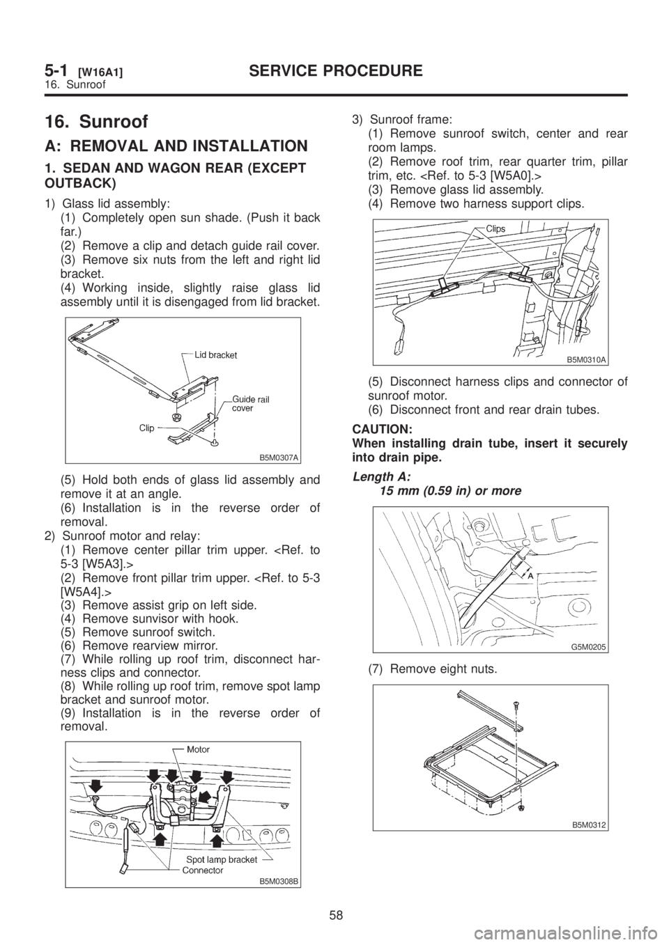
1) Glass lid assembly:
(1) Completely open sun shade. (Push it back
far.)
(2) Remove a clip and detach guide rail cover.
(3) Remove six nuts from the left and right lid
bracket.
(4) Working inside, slightly raise glass lid
assembly until it is disengaged from lid bracket.
B5M0307A
(5) Hold both ends of glass lid assembly and
remove it at an angle.
(6) Installation is in the reverse order of
removal.
2) Sunroof motor and relay:
(1) Remove center pillar trim upper.
5-3 [W5A3].>
(2) Remove front pillar trim upper.
[W5A4].>
(3) Remove assist grip on left side.
(4) Remove sunvisor with hook.
(5) Remove sunroof switch.
(6) Remove rearview mirror.
(7) While rolling up roof trim, disconnect har-
ness clips and connector.
(8) While rolling up roof trim, remove spot lamp
bracket and sunroof motor.
(9) Installation is in the reverse order of
removal.
B5M0308B
3) Sunroof frame:
(1) Remove sunroof switch, center and rear
room lamps.
(2) Remove roof trim, rear quarter trim, pillar
trim, etc.
(3) Remove glass lid assembly.
(4) Remove two harness support clips.
B5M0310A
(5) Disconnect harness clips and connector of
sunroof motor.
(6) Disconnect front and rear drain tubes.
CAUTION:
When installing drain tube, insert it securely
into drain pipe.
Length A:
15 mm (0.59 in) or more
G5M0205
(7) Remove eight nuts.
B5M0312
58
5-1[W16A1]SERVICE PROCEDURE
16. Sunroof
Page 1091 of 1456
18. Rear Spoiler
A: REMOVAL AND INSTALLATION
1) Open trunk lid.
2) Disconnect high-mount stop light connector
located inside the trunk lid.
3) Remove rubber caps.
B5M0413
4) Remove rear spoiler mounting nuts.
CAUTION:
When removing nuts, be careful not to drop
them inside rear gate.
B5M0414
5) Installation is in the reverse order of removal.
Tightening torque:
7.4
±2.0 N´m (0.75±0.2 kg-m, 5.4±1.4 ft-lb)
19. Roof Spoiler
A: REMOVAL AND INSTALLATION
1) Open rear gate and remove rear gate trim
upper and side.
B5M0305
2) Remove high-mount stop light.
[W6A4].>
3) Remove plastic caps and harness covers.
B5M0415A
4) Remove roof spoiler mounting nuts.
CAUTION:
IWhen removing nuts, be careful not to drop
them inside rear gate.
IBe careful since two-sided tape is placed
between roof spoiler and body panel.
B5M0306
5) Installation is in the reverse order of removal.
Tightening torque:
7.4
±2.0 N´m (0.75±0.2 kg-m, 5.4±1.4 ft-lb)
62
5-1[W18A0]SERVICE PROCEDURE
18. Rear Spoiler
Page 1092 of 1456
18. Rear Spoiler
A: REMOVAL AND INSTALLATION
1) Open trunk lid.
2) Disconnect high-mount stop light connector
located inside the trunk lid.
3) Remove rubber caps.
B5M0413
4) Remove rear spoiler mounting nuts.
CAUTION:
When removing nuts, be careful not to drop
them inside rear gate.
B5M0414
5) Installation is in the reverse order of removal.
Tightening torque:
7.4
±2.0 N´m (0.75±0.2 kg-m, 5.4±1.4 ft-lb)
19. Roof Spoiler
A: REMOVAL AND INSTALLATION
1) Open rear gate and remove rear gate trim
upper and side.
B5M0305
2) Remove high-mount stop light.
[W6A4].>
3) Remove plastic caps and harness covers.
B5M0415A
4) Remove roof spoiler mounting nuts.
CAUTION:
IWhen removing nuts, be careful not to drop
them inside rear gate.
IBe careful since two-sided tape is placed
between roof spoiler and body panel.
B5M0306
5) Installation is in the reverse order of removal.
Tightening torque:
7.4
±2.0 N´m (0.75±0.2 kg-m, 5.4±1.4 ft-lb)
62
5-1[W18A0]SERVICE PROCEDURE
18. Rear Spoiler
Page 1117 of 1456
![SUBARU LEGACY 1999 Service Repair Manual 10. GUSSET
1) Be sure window is all the way down.
2) Remove trim panel. <Ref. to 5-2 [W2A2].>
3) Remove door rearview mirror.
4) Remove sealing cover. <Ref. to 5-2 [W2A3].>
5) Remove bolts and nuts wh SUBARU LEGACY 1999 Service Repair Manual 10. GUSSET
1) Be sure window is all the way down.
2) Remove trim panel. <Ref. to 5-2 [W2A2].>
3) Remove door rearview mirror.
4) Remove sealing cover. <Ref. to 5-2 [W2A3].>
5) Remove bolts and nuts wh](/manual-img/17/57435/w960_57435-1116.png)
10. GUSSET
1) Be sure window is all the way down.
2) Remove trim panel.
3) Remove door rearview mirror.
4) Remove sealing cover.
5) Remove bolts and nuts which secure gusset
(A).
6) Lift out gusset (A).
B5M0070D
7) Installation is in the reverse order of removal.
11. REAR DOOR CATCHER
1) Open the rear door.
2) Using TORXTBIT (Tamper resistant type),
remove rear door catcher.
B5M0467A
3) Installation is in the reverse order of removal.
Tightening torque:
37
±10 N´m (3.8±1.0 kg-m, 27.5±7.2 ft-lb)
B: ADJUSTMENT
1. DOOR ASSEMBLY
1) Using ST, loosen bolts securing upper and
lower hinges to body, and adjust fore-and-aft and
vertical alignment of door.
ST 925610000 DOOR HINGE WRENCH
2) Loosen mounting screws approximately one
rotation. Adjust striker (A) position by lightly tap-
ping with hammer. (To adjust, utilize the shape of
striker nut plate support (B).)
CAUTION:
IUse cloth to prevent damaging body or other
parts.
IDo not directly tap striker plastic portion.
IDo not apply impact on spot-welded striker
nut plate.
Hinge tightening torque (body side):
29
±5 N´m (3.0±0.5 kg-m, 21.7±3.6 ft-lb)
Striker tightening torque:
14
±4 N´m (1.4±0.4 kg-m, 10.1±2.9 ft-lb)
B5M0071C
18
5-2[W2A10]SERVICE PROCEDURE
2. Door
Page 1120 of 1456
4. FRONT DOOR GLASS
B5M0072B
IDoor glass fit adjustment
Before adjusting door glass alignment, ensure
adjusting bolts for stabilizers, upper stoppers and
sashes are loose and glass is raised so that it is in
contact with upper and side weatherstrip.
1) Temporarily tighten one of the two rear sash
adjusting bolts, at midpoint of oblong hole on inner
panel.
2) Temporarily tighten B channel regulator at a
position slightly lower than midpoint of oblong hole
on inner panel.
21
[W2B4]5-2SERVICE PROCEDURE
2. Door
Page 1123 of 1456
5. REAR DOOR GLASS
Alignment of rear door glass is basically the same as for the front door glass. Due to slight difference in
adjustment dimensions for fore-aft, up-down, and in-out alignments, key points for rear door adjustment are
described.
B5M0078B
24
5-2[W2B5]SERVICE PROCEDURE
2. Door
Page 1125 of 1456

3. Rear Gate
A: REMOVAL AND INSTALLATION
CAUTION:
IBe careful not to scratch coated surfaces of
vehicle body and window glass during
removal. Place a cloth over the affected area.
IBe careful not to damage trim panels.
IUse an assistant when handling heavy parts.
IBe careful not to damage or lose small parts.
1. REAR GATE ASSEMBLY
1) Remove clips from trim panel and detach trim
panel.
CAUTION:
Be careful not to damage clips or their holes.
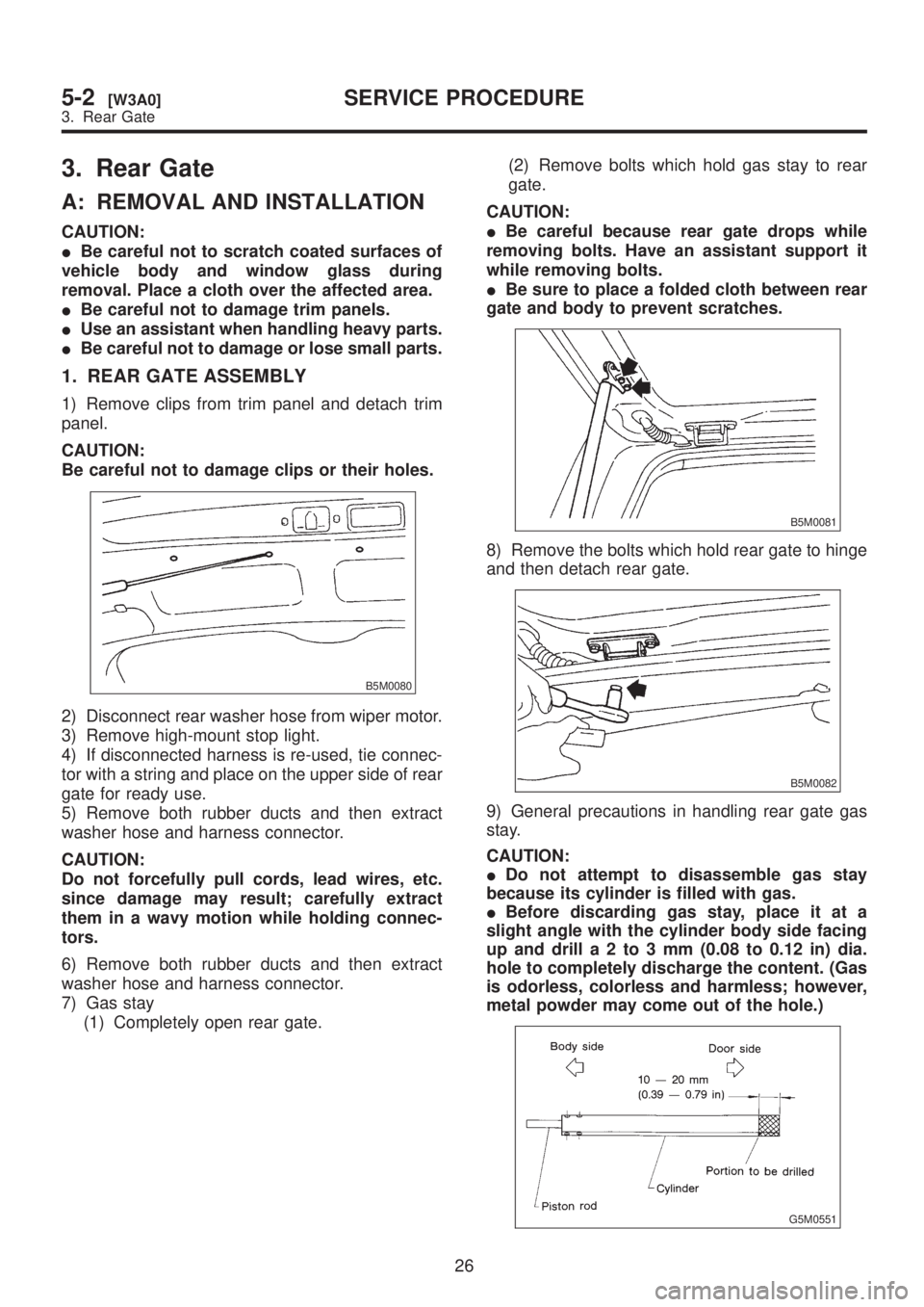
B5M0080
2) Disconnect rear washer hose from wiper motor.
3) Remove high-mount stop light.
4) If disconnected harness is re-used, tie connec-
tor with a string and place on the upper side of rear
gate for ready use.
5) Remove both rubber ducts and then extract
washer hose and harness connector.
CAUTION:
Do not forcefully pull cords, lead wires, etc.
since damage may result; carefully extract
them in a wavy motion while holding connec-
tors.
6) Remove both rubber ducts and then extract
washer hose and harness connector.
7) Gas stay
(1) Completely open rear gate.(2) Remove bolts which hold gas stay to rear
gate.
CAUTION:
IBe careful because rear gate drops while
removing bolts. Have an assistant support it
while removing bolts.
IBe sure to place a folded cloth between rear
gate and body to prevent scratches.
B5M0081
8) Remove the bolts which hold rear gate to hinge
and then detach rear gate.
B5M0082
9) General precautions in handling rear gate gas
stay.
CAUTION:
IDo not attempt to disassemble gas stay
because its cylinder is filled with gas.
IBefore discarding gas stay, place it at a
slight angle with the cylinder body side facing
up and drilla2to3mm(0.08 to 0.12 in) dia.
hole to completely discharge the content. (Gas
is odorless, colorless and harmless; however,
metal powder may come out of the hole.)
G5M0551
26
5-2[W3A0]SERVICE PROCEDURE
3. Rear Gate
Page 1133 of 1456

(3) Stick them fast by pressing all sides lightly.
10) Installation of molding:
(1) Remove adhesive overflowing from outside
of glass until it becomes level with outer height
of glass. Then, add adhesive to portions that
need it, and clean with alcohol or white gaso-
line.
G5M0496
(2) Install front side molding.
CAUTION:
Do not open and close door after moldings
have been installed. When opening and closing
door for unavoidable reason, lower door glass
and gently move door.
11) Water leakage test:
Test for water leakage about one hour after instal-
lation.
CAUTION:
IMove vehicle very gently.
IDo not squirt strong hose stream on vehicle.
12) Spontaneous drying:
After completing all operations, leave vehicle alone
for 24 hours.
CAUTION:
When delivering vehicle to user, tell him that
vehicle should not be subjected to heavy
shocks for at least three days.
13) Install cowl panel and wiper arm.
6. Rear Window Glass
A: REMOVAL
1. SEDAN
1) Disconnect connector from rear defogger termi-
nal.
2) Remove glass in the same manner as in wind-
shield.
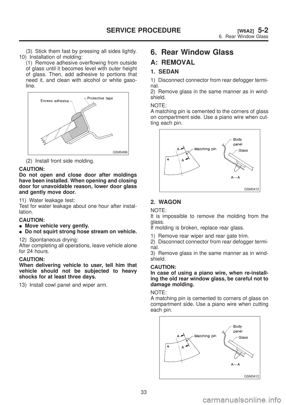
NOTE:
A matching pin is cemented to the corners of glass
on compartment side. Use a piano wire when cut-
ting each pin.
G5M0412
2. WAGON
NOTE:
It is impossible to remove the molding from the
glass.
If molding is broken, replace rear glass.
1) Remove rear wiper and rear gate trim.
2) Disconnect connector from rear defogger termi-
nal.
3) Remove glass in the same manner as in wind-
shield.
CAUTION:
In case of using a piano wire, when re-install-
ing the old rear window glass, be careful not to
damage molding.
NOTE:
A matching pin is cemented to corners of glass on
compartment side. Use a piano wire when cutting
each pin.
G5M0412
33
[W6A2]5-2SERVICE PROCEDURE
6. Rear Window Glass