1999 SUBARU LEGACY light
[x] Cancel search: lightPage 915 of 1456
3. OPERATION CHECK
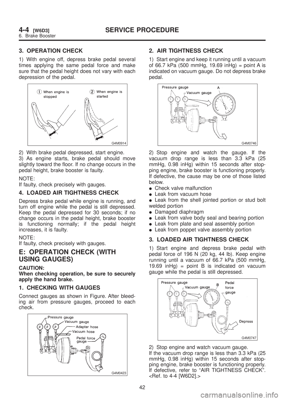
1) With engine off, depress brake pedal several
times applying the same pedal force and make
sure that the pedal height does not vary with each
depression of the pedal.
G4M0914
2) With brake pedal depressed, start engine.
3) As engine starts, brake pedal should move
slightly toward the floor. If no change occurs in the
pedal height, brake booster is faulty.
NOTE:
If faulty, check precisely with gauges.
4. LOADED AIR TIGHTNESS CHECK
Depress brake pedal while engine is running, and
turn off engine while the pedal is still depressed.
Keep the pedal depressed for 30 seconds; if no
change occurs in the pedal height, brake booster
is functioning normally; if the pedal height
increases, it is faulty.
NOTE:
If faulty, check precisely with gauges.
E: OPERATION CHECK (WITH
USING GAUGES)
CAUTION:
When checking operation, be sure to securely
apply the hand brake.
1. CHECKING WITH GAUGES
Connect gauges as shown in Figure. After bleed-
ing air from pressure gauges, proceed to each
check.
G4M0423
2. AIR TIGHTNESS CHECK
1) Start engine and keep it running until a vacuum
of 66.7 kPa (500 mmHg, 19.69 inHg) = point A is
indicated on vacuum gauge. Do not depress brake
pedal.
G4M0746
2) Stop engine and watch the gauge. If the
vacuum drop range is less than 3.3 kPa (25
mmHg, 0.98 inHg) within 15 seconds after stop-
ping engine, brake booster is functioning properly.
If defective, the cause may be one of those listed
below.
ICheck valve malfunction
ILeak from vacuum hose
ILeak from the shell jointed portion or stud bolt
welded portion
IDamaged diaphragm
ILeak from valve body seal and bearing portion
ILeak from plate and seal assembly portion
ILeak from poppet valve assembly portion
3. LOADED AIR TIGHTNESS CHECK
1) Start engine and depress brake pedal with
pedal force of 196 N (20 kg, 44 lb). Keep engine
running until a vacuum of 66.7 kPa (500 mmHg,
19.69 inHg) = point B is indicated on vacuum
gauge while the pedal is still depressed.
G4M0747
2) Stop engine and watch vacuum gauge.
If the vacuum drop range is less than 3.3 kPa (25
mmHg, 0.98 inHg) within 15 seconds after stop-
ping engine, brake booster is functioning properly.
If defective, refer to ªAIR TIGHTNESS CHECKº.
42
4-4[W6D3]SERVICE PROCEDURE
6. Brake Booster
Page 918 of 1456
7) While holding hexagonal part of brake hose fit-
ting with a wrench, tighten flare nut to the specified
torque.
Tightening torque (Brake pipe flare nut):
15+3/þ2N´m (1.5+0.3/þ0.2kg-m, 10.8+2.2/þ1.4ft-lb)
8) Bleed air from the brake system.
2. REAR BRAKE HOSE
1) Pass brake hose through the hole of bracket,
and lightly tighten flare nut to connect brake pipe.
2) Insert clamp upward to fix brake hose.
3) While holding hexagonal part of brake hose fit-
ting with a wrench, tighten flare nut to the specified
torque.
Tightening torque (Brake pipe flare nut):
15+3/þ2N´m (1.5+0.3/þ0.2kg-m, 10.8+2.2/þ1.4ft-lb)
4) Bleed air from the brake system.
8. Hill Holder
A: REMOVAL
1) Drain brake fluid from reservoir of master cylin-
der.
2) Remove adjusting nut and cable clamp, and
disconnect PHV cable from cable bracket on
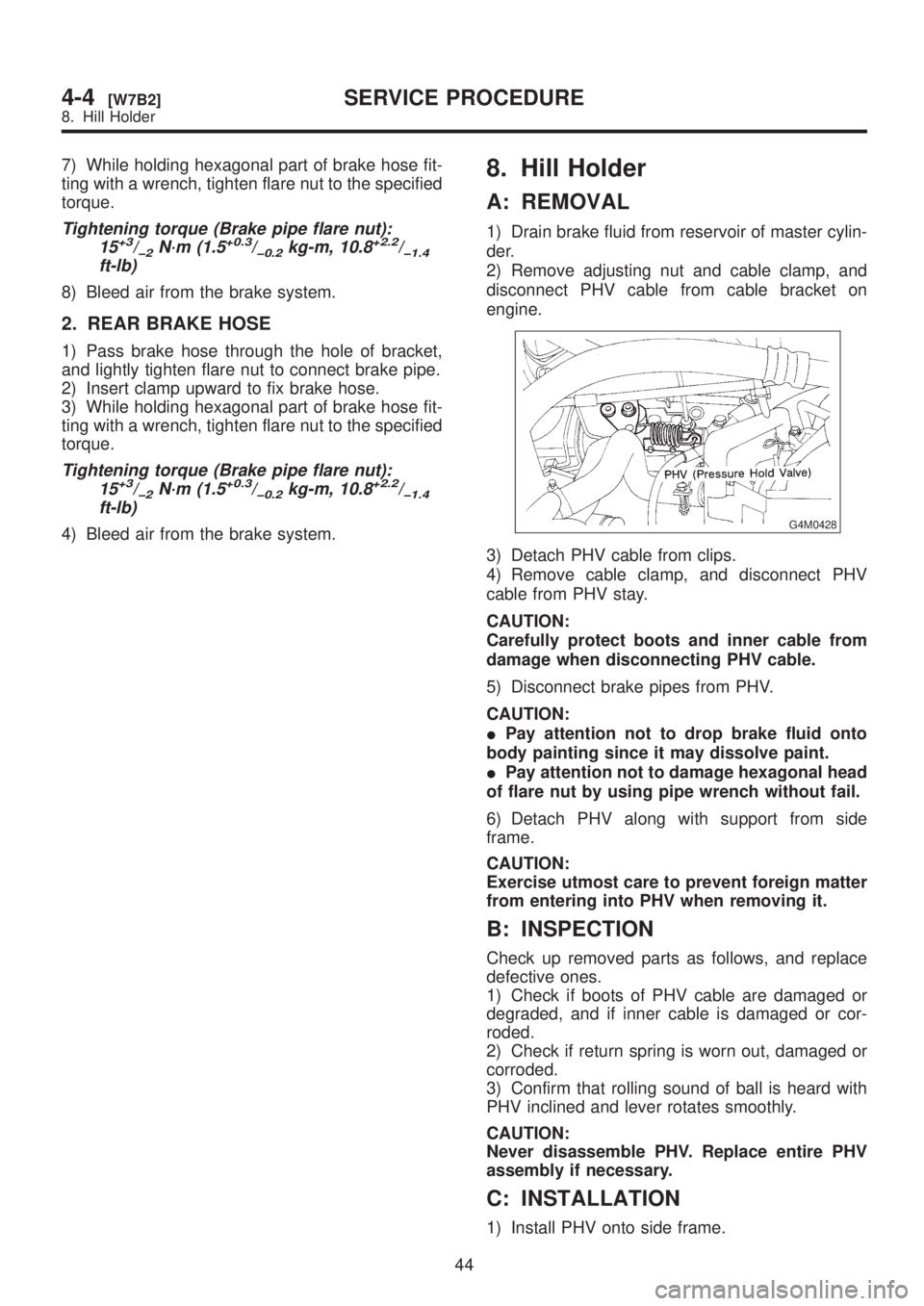
engine.
G4M0428
3) Detach PHV cable from clips.
4) Remove cable clamp, and disconnect PHV
cable from PHV stay.
CAUTION:
Carefully protect boots and inner cable from
damage when disconnecting PHV cable.
5) Disconnect brake pipes from PHV.
CAUTION:
IPay attention not to drop brake fluid onto
body painting since it may dissolve paint.
IPay attention not to damage hexagonal head
of flare nut by using pipe wrench without fail.
6) Detach PHV along with support from side
frame.
CAUTION:
Exercise utmost care to prevent foreign matter
from entering into PHV when removing it.
B: INSPECTION
Check up removed parts as follows, and replace
defective ones.
1) Check if boots of PHV cable are damaged or
degraded, and if inner cable is damaged or cor-
roded.
2) Check if return spring is worn out, damaged or
corroded.
3) Confirm that rolling sound of ball is heard with
PHV inclined and lever rotates smoothly.
CAUTION:
Never disassemble PHV. Replace entire PHV
assembly if necessary.
C: INSTALLATION
1) Install PHV onto side frame.
44
4-4[W7B2]SERVICE PROCEDURE
8. Hill Holder
Page 919 of 1456
7) While holding hexagonal part of brake hose fit-
ting with a wrench, tighten flare nut to the specified
torque.
Tightening torque (Brake pipe flare nut):
15+3/þ2N´m (1.5+0.3/þ0.2kg-m, 10.8+2.2/þ1.4ft-lb)
8) Bleed air from the brake system.
2. REAR BRAKE HOSE
1) Pass brake hose through the hole of bracket,
and lightly tighten flare nut to connect brake pipe.
2) Insert clamp upward to fix brake hose.
3) While holding hexagonal part of brake hose fit-
ting with a wrench, tighten flare nut to the specified
torque.
Tightening torque (Brake pipe flare nut):
15+3/þ2N´m (1.5+0.3/þ0.2kg-m, 10.8+2.2/þ1.4ft-lb)
4) Bleed air from the brake system.
8. Hill Holder
A: REMOVAL
1) Drain brake fluid from reservoir of master cylin-
der.
2) Remove adjusting nut and cable clamp, and
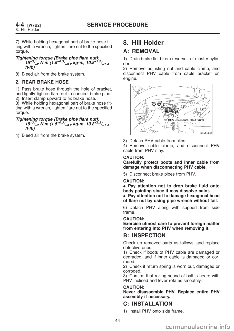
disconnect PHV cable from cable bracket on
engine.
G4M0428
3) Detach PHV cable from clips.
4) Remove cable clamp, and disconnect PHV
cable from PHV stay.
CAUTION:
Carefully protect boots and inner cable from
damage when disconnecting PHV cable.
5) Disconnect brake pipes from PHV.
CAUTION:
IPay attention not to drop brake fluid onto
body painting since it may dissolve paint.
IPay attention not to damage hexagonal head
of flare nut by using pipe wrench without fail.
6) Detach PHV along with support from side
frame.
CAUTION:
Exercise utmost care to prevent foreign matter
from entering into PHV when removing it.
B: INSPECTION
Check up removed parts as follows, and replace
defective ones.
1) Check if boots of PHV cable are damaged or
degraded, and if inner cable is damaged or cor-
roded.
2) Check if return spring is worn out, damaged or
corroded.
3) Confirm that rolling sound of ball is heard with
PHV inclined and lever rotates smoothly.
CAUTION:
Never disassemble PHV. Replace entire PHV
assembly if necessary.
C: INSTALLATION
1) Install PHV onto side frame.
44
4-4[W7B2]SERVICE PROCEDURE
8. Hill Holder
Page 920 of 1456
Tightening torque:
18
±5 N´m (1.8±0.5 kg-m, 13.0±3.6 ft-lb)
2) Connect brake pipes to PHV.
Tightening torque:
15+3/þ2N´m (1.5+0.3/þ0.2kg-m, 10.8+2.2/þ1.4ft-lb)
CAUTION:
Confirm that brake pipes are not deformed
and/or damaged. Replace them with new ones
if necessary.
3) Install PHV cable to PHV stay.
CAUTION:
If cable clamp (and clips) is damaged, replace
it with a new one.
4) Connect PHV cable with clips.
NOTE:
Avoid sharp bending of PHV cable as it may cause
breakage.
5) Install PHV cable onto cable bracket on engine.
6) Apply grease to the following points.
IHook portion of return spring
ICable end portion of lever
Grease:
SUNLIGHT 2 (Part No. 003602010)
7) Be sure to bleed air from the system.
CAUTION:
After replacing PHV cable or clutch cable with
new one, operate clutch pedal about 30 times
as a running-in operation prior to adjustment.
D: ADJUSTMENTS
Confirm stopping and starting performances by
activating hill holder on an uphill road of 3É or
higher inclination.
1) If vehicle does not stop;
Tighten adjusting nut of PHV cable.
2) If vehicle does not start properly;
ICase A Ð When hill holder is released later than
engagement of clutch pedal (Engine tends to
stall.):
Loosen adjusting nut gradually until smooth start-
ing is enabled.
ICase B Ð When hill holder is released earlier
than engagement of clutch pedal (Vehicle slips
down slightly.):
Tighten adjusting nut so that hill holder is released
later than engagement of clutch pedal (status in
Case A). Then make adjustment the same as in
Case A.NOTE:
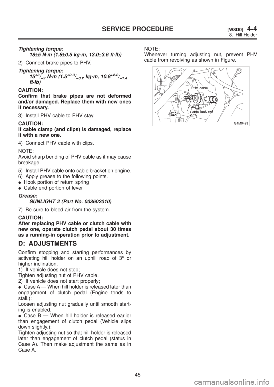
Whenever turning adjusting nut, prevent PHV
cable from revolving as shown in Figure.
G4M0429
45
[W8D0]4-4SERVICE PROCEDURE
8. Hill Holder
Page 935 of 1456
4) Within 0.5 seconds after the ABS warning light
goes out, depress the brake pedal and hold it
immediately after ignition switch is turned to ON.
CAUTION:
Do not depress the clutch pedal.
NOTE:
IWhen the ignition switch is set to on, the brake
pedal must not be depressed.
IEngine must not operate.
5) After completion of ABS sequence control, turn
ignition switch OFF.
2. OPERATIONAL GUIDELINES OF THE
ABS SEQUENCE CONTROL WITH
SELECT MONITOR
NOTE:
IIn the event of any trouble, the sequence con-
trol may not be operative. In such a case, activate
the sequence control, referring to ªOPERATIONAL
GUIDELINES OF THE ABS SEQUENCE CON-
TROL WITH DIAGNOSIS CONNECTORº.
IWhen the diagnosis terminal is connected to the
diagnosis connector, the sequence control will not
operate.
1) Connect select monitor to data link connector
beside driver's seat instrument panel lower cover.
2) Turn ignition switch ON.
3) Turn select monitor switch ON.
4) Put select monitor to {ABS/TCS} mode.
5) When {Function check sequence} is selected,
`ABS sequence control' will start.
6) The message `Press Brake Pedal Firmly' is dis-
played as follows:
(1) When using the brake tester, depress brake
pedal with braking force of 981 N (100 kg, 221
lb).
(2) When using the pressure gauge, depress
brake pedal so as to make the pressure gauge
indicate 3,432 kPa (35 kg/cm
2, 498 psi).
CAUTION:
Do not depress the clutch pedal.
7) When the message ªPress YESº is displayed,
press YES key.
8) Operation points will be displayed on select
monitor.
3. CONDITIONS FOR COMPLETION OF
ABS SEQUENCE CONTROL
When the following conditions develop, the ABS
sequence control stops and ABS operation is
returned to the normal control mode.
1) When the speed of at least one wheel reaches
10 km/h (6 MPH).
2) When terminal No. 3 or No. 6 are separated
from diagnosis terminals. (When select monitor is
not used.)
3) When the brake pedal is released during
sequence control and the braking lamp switch is
set to off.
4) When brake pedal is depressed after ignition
key is turned to ON, and before ABS warning light
goes out. (When select monitor is not used.)
5) When brake pedal is not depressed after igni-
tion key is turned to ON, and within 0.5 seconds
after ABS warning light goes out. (When select
monitor is not used.)
6) After completion of the sequence control.
7) When malfunction is detected. (When select
monitor is used.)
58
4-4[W15D2]SERVICE PROCEDURE
15. ABS Control Module and Hydraulic Control Unit (ABSCM&H/U)
Page 948 of 1456
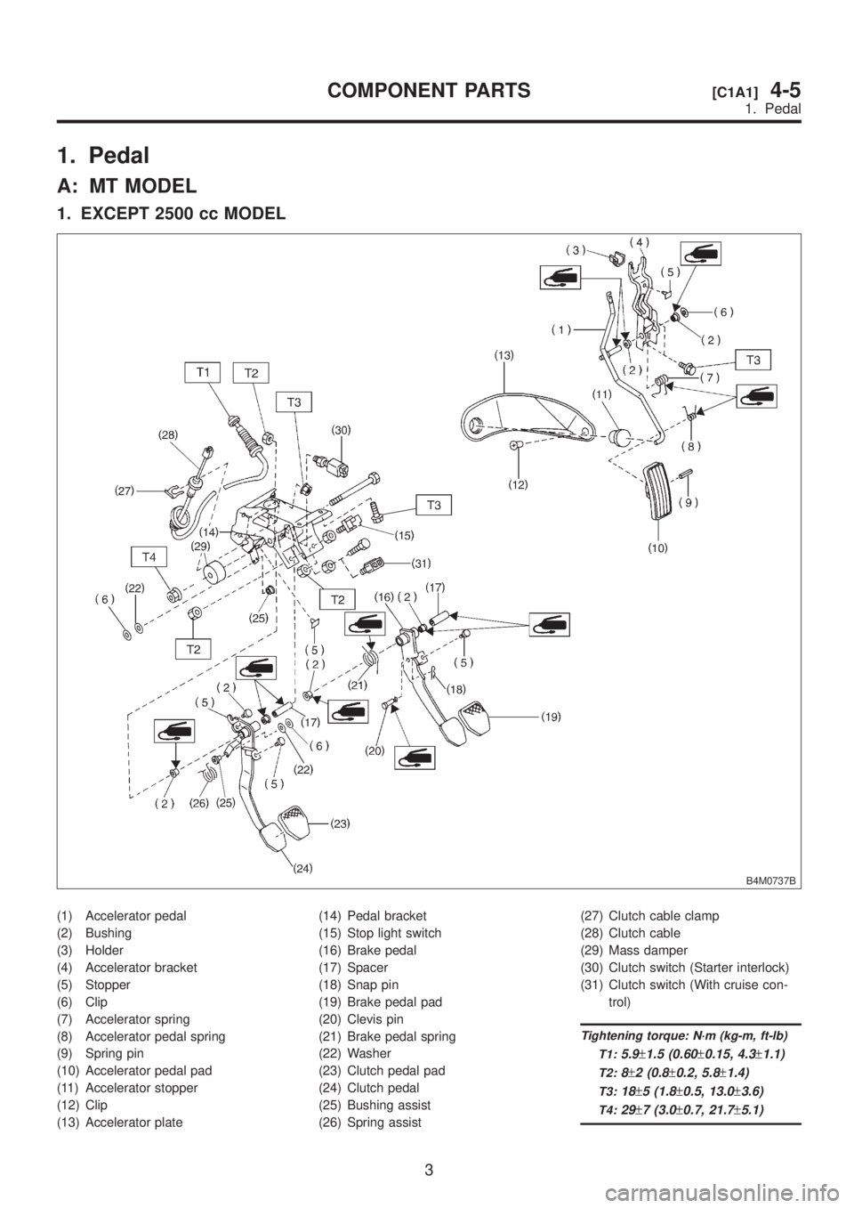
1. Pedal
A: MT MODEL
1. EXCEPT 2500 cc MODEL
B4M0737B
(1) Accelerator pedal
(2) Bushing
(3) Holder
(4) Accelerator bracket
(5) Stopper
(6) Clip
(7) Accelerator spring
(8) Accelerator pedal spring
(9) Spring pin
(10) Accelerator pedal pad
(11) Accelerator stopper
(12) Clip
(13) Accelerator plate(14) Pedal bracket
(15) Stop light switch
(16) Brake pedal
(17) Spacer
(18) Snap pin
(19) Brake pedal pad
(20) Clevis pin
(21) Brake pedal spring
(22) Washer
(23) Clutch pedal pad
(24) Clutch pedal
(25) Bushing assist
(26) Spring assist(27) Clutch cable clamp
(28) Clutch cable
(29) Mass damper
(30) Clutch switch (Starter interlock)
(31) Clutch switch (With cruise con-
trol)
Tightening torque: N´m (kg-m, ft-lb)
T1:
5.9±1.5 (0.60±0.15, 4.3±1.1)
T2:8±2 (0.8±0.2, 5.8±1.4)
T3:18±5 (1.8±0.5, 13.0±3.6)
T4:29±7 (3.0±0.7, 21.7±5.1)
3
[C1A1]4-5COMPONENT PARTS
1. Pedal
Page 949 of 1456
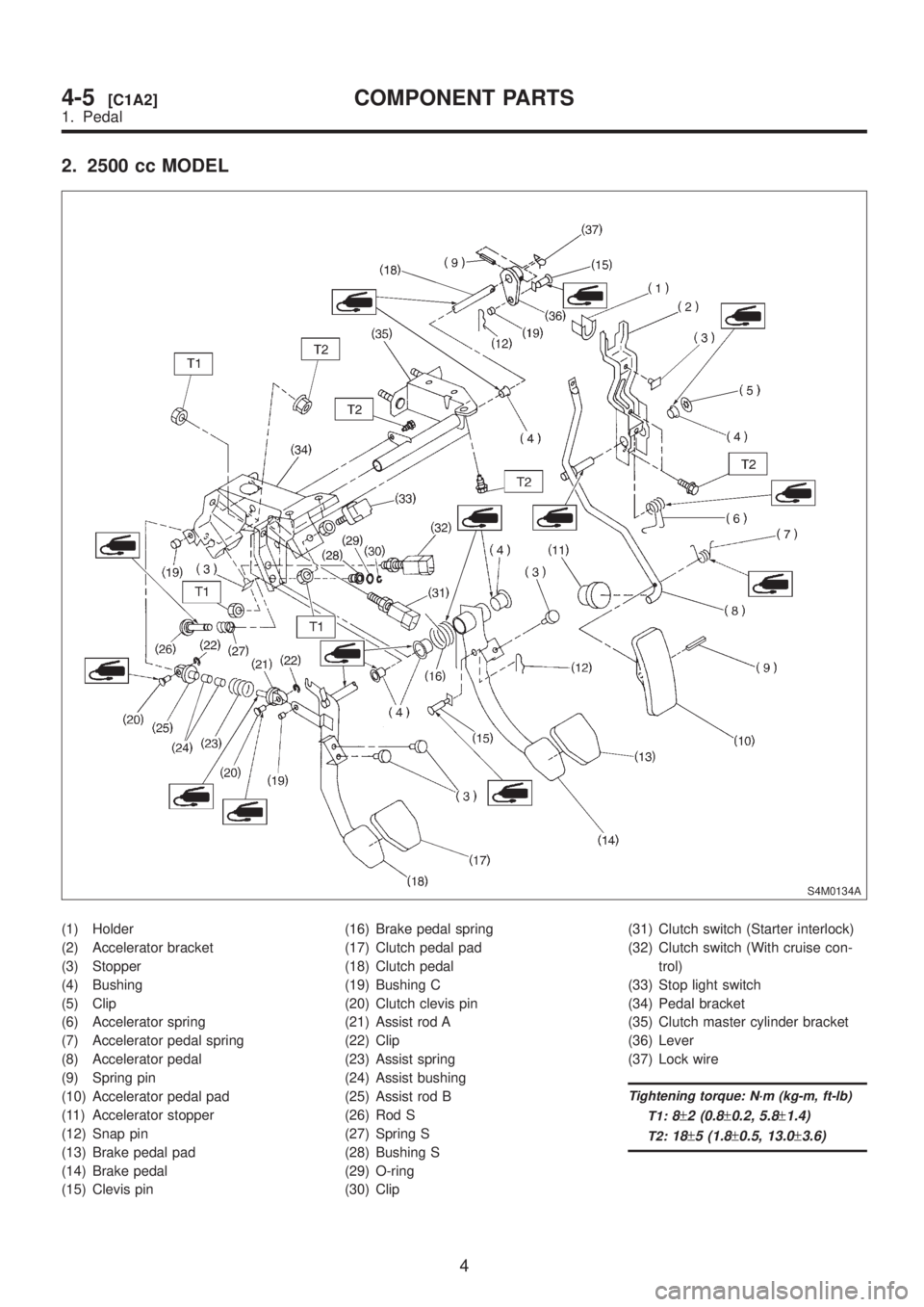
2. 2500 cc MODEL
S4M0134A
(1) Holder
(2) Accelerator bracket
(3) Stopper
(4) Bushing
(5) Clip
(6) Accelerator spring
(7) Accelerator pedal spring
(8) Accelerator pedal
(9) Spring pin
(10) Accelerator pedal pad
(11) Accelerator stopper
(12) Snap pin
(13) Brake pedal pad
(14) Brake pedal
(15) Clevis pin(16) Brake pedal spring
(17) Clutch pedal pad
(18) Clutch pedal
(19) Bushing C
(20) Clutch clevis pin
(21) Assist rod A
(22) Clip
(23) Assist spring
(24) Assist bushing
(25) Assist rod B
(26) Rod S
(27) Spring S
(28) Bushing S
(29) O-ring
(30) Clip(31) Clutch switch (Starter interlock)
(32) Clutch switch (With cruise con-
trol)
(33) Stop light switch
(34) Pedal bracket
(35) Clutch master cylinder bracket
(36) Lever
(37) Lock wire
Tightening torque: N´m (kg-m, ft-lb)
T1:
8±2 (0.8±0.2, 5.8±1.4)
T2:18±5 (1.8±0.5, 13.0±3.6)
4
4-5[C1A2]COMPONENT PARTS
1. Pedal
Page 950 of 1456
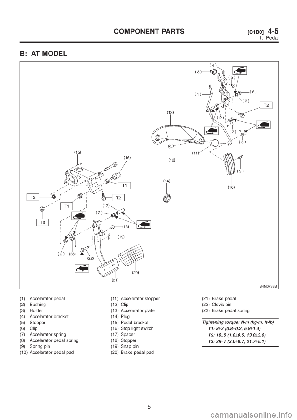
B: AT MODEL
B4M0738B
(1) Accelerator pedal
(2) Bushing
(3) Holder
(4) Accelerator bracket
(5) Stopper
(6) Clip
(7) Accelerator spring
(8) Accelerator pedal spring
(9) Spring pin
(10) Accelerator pedal pad(11) Accelerator stopper
(12) Clip
(13) Accelerator plate
(14) Plug
(15) Pedal bracket
(16) Stop light switch
(17) Spacer
(18) Stopper
(19) Snap pin
(20) Brake pedal pad(21) Brake pedal
(22) Clevis pin
(23) Brake pedal spring
Tightening torque: N´m (kg-m, ft-lb)
T1:
8±2 (0.8±0.2, 5.8±1.4)
T2:18±5 (1.8±0.5, 13.0±3.6)
T3:29±7 (3.0±0.7, 21.7±5.1)
5
[C1B0]4-5COMPONENT PARTS
1. Pedal