1999 SUBARU LEGACY light
[x] Cancel search: lightPage 951 of 1456
1. Pedal
A: ON-CAR SERVICE
1. BRAKE PEDAL
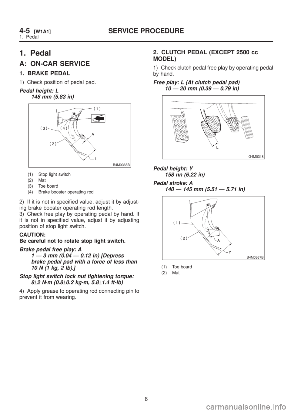
1) Check position of pedal pad.
Pedal height: L
148 mm (5.83 in)
B4M0366B
(1) Stop light switch
(2) Mat
(3) Toe board
(4) Brake booster operating rod
2) If it is not in specified value, adjust it by adjust-
ing brake booster operating rod length.
3) Check free play by operating pedal by hand. If
it is not in specified value, adjust it by adjusting
position of stop light switch.
CAUTION:
Be careful not to rotate stop light switch.
Brake pedal free play: A
1Ð3mm(0.04 Ð 0.12 in) [Depress
brake pedal pad with a force of less than
10 N (1 kg, 2 lb).]
Stop light switch lock nut tightening torque:
8
±2 N´m (0.8±0.2 kg-m, 5.8±1.4 ft-lb)
4) Apply grease to operating rod connecting pin to
prevent it from wearing.
2. CLUTCH PEDAL (EXCEPT 2500 cc
MODEL)
1) Check clutch pedal free play by operating pedal
by hand.
Free play: L (At clutch pedal pad)
10 Ð 20 mm (0.39 Ð 0.79 in)
G4M0318
Pedal height: Y
158 nn (6.22 in)
Pedal stroke: A
140 Ð 145 mm (5.51 Ð 5.71 in)
B4M0367B
(1) Toe board
(2) Mat
6
4-5[W1A1]SERVICE PROCEDURE
1. Pedal
Page 953 of 1456
B: REMOVAL
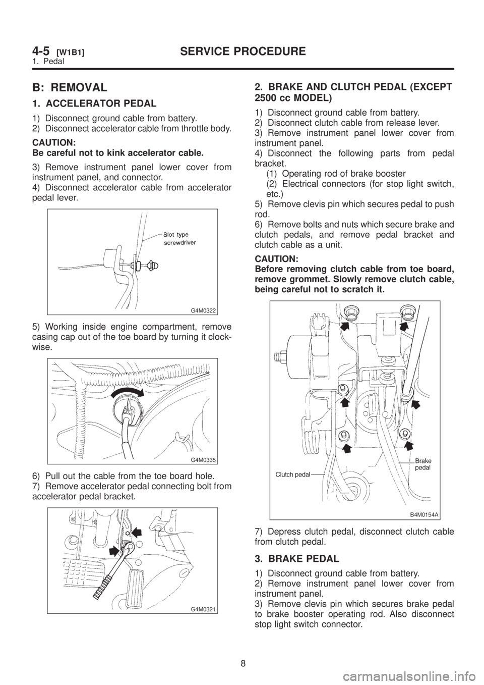
1. ACCELERATOR PEDAL
1) Disconnect ground cable from battery.
2) Disconnect accelerator cable from throttle body.
CAUTION:
Be careful not to kink accelerator cable.
3) Remove instrument panel lower cover from
instrument panel, and connector.
4) Disconnect accelerator cable from accelerator
pedal lever.
G4M0322
5) Working inside engine compartment, remove
casing cap out of the toe board by turning it clock-
wise.
G4M0335
6) Pull out the cable from the toe board hole.
7) Remove accelerator pedal connecting bolt from
accelerator pedal bracket.
G4M0321
2. BRAKE AND CLUTCH PEDAL (EXCEPT
2500 cc MODEL)
1) Disconnect ground cable from battery.
2) Disconnect clutch cable from release lever.
3) Remove instrument panel lower cover from
instrument panel.
4) Disconnect the following parts from pedal
bracket.
(1) Operating rod of brake booster
(2) Electrical connectors (for stop light switch,
etc.)
5) Remove clevis pin which secures pedal to push
rod.
6) Remove bolts and nuts which secure brake and
clutch pedals, and remove pedal bracket and
clutch cable as a unit.
CAUTION:
Before removing clutch cable from toe board,
remove grommet. Slowly remove clutch cable,
being careful not to scratch it.
B4M0154A
7) Depress clutch pedal, disconnect clutch cable
from clutch pedal.
3. BRAKE PEDAL
1) Disconnect ground cable from battery.
2) Remove instrument panel lower cover from
instrument panel.
3) Remove clevis pin which secures brake pedal
to brake booster operating rod. Also disconnect
stop light switch connector.
8
4-5[W1B1]SERVICE PROCEDURE
1. Pedal
Page 954 of 1456

4) Remove two bolts and four nuts which secure
brake pedal to pedal.
G4M0324
4. BRAKE AND CLUTCH PEDAL (2500 cc
MODEL)
1) Remove steering bolts.
2) Raise vehicle on hoist and remove the two bolts
which secure steering unit to underside of body.
3) Lower vehicle to floor.
4) Remove instrument panel lower cover from
instrument panel.
5) Disconnect the following parts from pedal
bracket.
IOperating rod of brake booster
IElectrical connectors (for stop light switch, etc.)
6) Remove clevis pin which secures lever to push
rod.
7) Remove nut which secures clutch master cylin-
der.
8) Remove steering assembly.
9) Remove bolts and nuts which secure brake and
clutch pedals, and remove pedal assembly.
C: INSPECTION
1. BRAKE AND CLUTCH PEDALS
Move brake and clutch pedal pads in the lateral
direction with a force of approximately 10 N (1 kg,
2 lb) to ensure pedal deflection is in specified
range.
Deflection of brake and clutch pedal:
Service limit
5.0 mm (0.197 in) or less
CAUTION:
If excessive deflection is noted, replace bush-
ings with new ones.
S4M0135A
G4M0326
9
[W1C1]4-5SERVICE PROCEDURE
1. Pedal
Page 955 of 1456
2. ACCELERATOR PEDAL
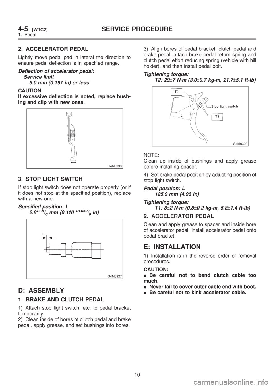
Lightly move pedal pad in lateral the direction to
ensure pedal deflection is in specified range.
Deflection of accelerator pedal:
Service limit
5.0 mm (0.197 in) or less
CAUTION:
If excessive deflection is noted, replace bush-
ing and clip with new ones.
G4M0333
3. STOP LIGHT SWITCH
If stop light switch does not operate properly (or if
it does not stop at the specified position), replace
with a new one.
Specified position: L
2.8+1.5/0mm (0.110+0.059/0in)
G4M0327
D: ASSEMBLY
1. BRAKE AND CLUTCH PEDAL
1) Attach stop light switch, etc. to pedal bracket
temporarily.
2) Clean inside of bores of clutch pedal and brake
pedal, apply grease, and set bushings into bores.3) Align bores of pedal bracket, clutch pedal and
brake pedal, attach brake pedal return spring and
clutch pedal effort reducing spring (vehicle with hill
holder), and then install pedal bolt.
Tightening torque:
T2: 29
±7 N´m (3.0±0.7 kg-m, 21.7±5.1 ft-lb)
G4M0329
NOTE:
Clean up inside of bushings and apply grease
before installing spacer.
4) Set brake pedal position by adjusting position of
stop light switch.
Pedal position: L
125.9 mm (4.96 in)
Tightening torque:
T1: 8
±2 N´m (0.8±0.2 kg-m, 5.8±1.4 ft-lb)
2. ACCELERATOR PEDAL
Clean and apply grease to spacer and inside bore
of accelerator pedal. Install accelerator pedal onto
pedal bracket.
E: INSTALLATION
1) Installation is in the reverse order of removal
procedures.
CAUTION:
IBe careful not to bend clutch cable too
much.
INever fail to cover outer cable end with boot.
IBe careful not to kink accelerator cable.
10
4-5[W1C2]SERVICE PROCEDURE
1. Pedal
Page 960 of 1456
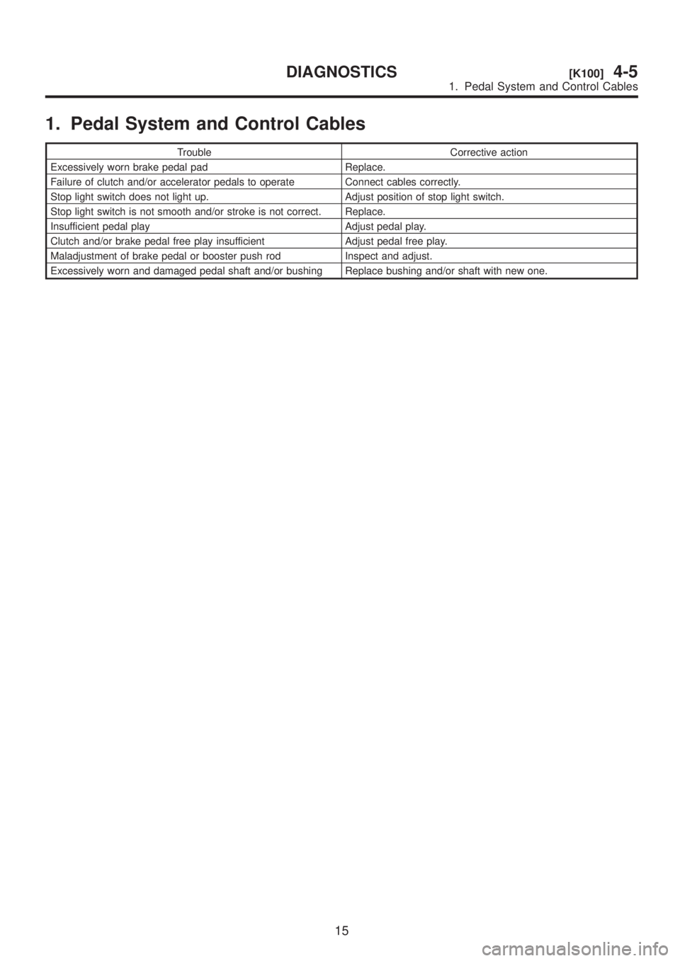
1. Pedal System and Control Cables
Trouble Corrective action
Excessively worn brake pedal pad Replace.
Failure of clutch and/or accelerator pedals to operate Connect cables correctly.
Stop light switch does not light up. Adjust position of stop light switch.
Stop light switch is not smooth and/or stroke is not correct. Replace.
Insufficient pedal play Adjust pedal play.
Clutch and/or brake pedal free play insufficient Adjust pedal free play.
Maladjustment of brake pedal or booster push rod Inspect and adjust.
Excessively worn and damaged pedal shaft and/or bushing Replace bushing and/or shaft with new one.
15
[K100]4-5DIAGNOSTICS
1. Pedal System and Control Cables
Page 982 of 1456
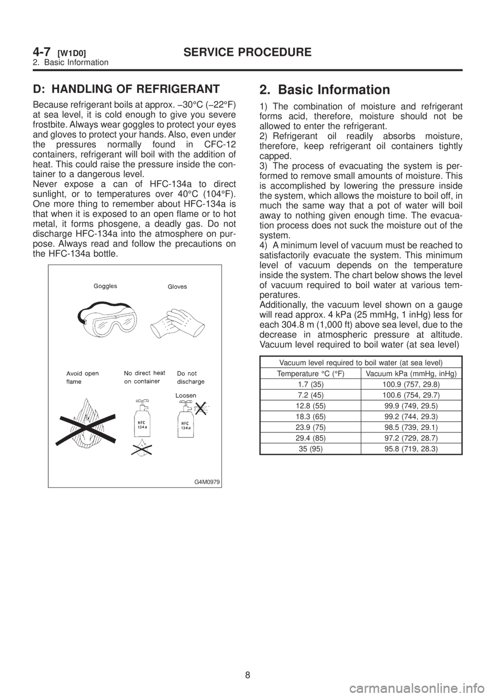
D: HANDLING OF REFRIGERANT
Because refrigerant boils at approx. þ30ÉC (þ22ÉF)
at sea level, it is cold enough to give you severe
frostbite. Always wear goggles to protect your eyes
and gloves to protect your hands. Also, even under
the pressures normally found in CFC-12
containers, refrigerant will boil with the addition of
heat. This could raise the pressure inside the con-
tainer to a dangerous level.
Never expose a can of HFC-134a to direct
sunlight, or to temperatures over 40ÉC (104ÉF).
One more thing to remember about HFC-134a is
that when it is exposed to an open flame or to hot
metal, it forms phosgene, a deadly gas. Do not
discharge HFC-134a into the atmosphere on pur-
pose. Always read and follow the precautions on
the HFC-134a bottle.
G4M0979
2. Basic Information
1) The combination of moisture and refrigerant
forms acid, therefore, moisture should not be
allowed to enter the refrigerant.
2) Refrigerant oil readily absorbs moisture,
therefore, keep refrigerant oil containers tightly
capped.
3) The process of evacuating the system is per-
formed to remove small amounts of moisture. This
is accomplished by lowering the pressure inside
the system, which allows the moisture to boil off, in
much the same way that a pot of water will boil
away to nothing given enough time. The evacua-
tion process does not suck the moisture out of the
system.
4) A minimum level of vacuum must be reached to
satisfactorily evacuate the system. This minimum
level of vacuum depends on the temperature
inside the system. The chart below shows the level
of vacuum required to boil water at various tem-
peratures.
Additionally, the vacuum level shown on a gauge
will read approx. 4 kPa (25 mmHg, 1 inHg) less for
each 304.8 m (1,000 ft) above sea level, due to the
decrease in atmospheric pressure at altitude.
Vacuum level required to boil water (at sea level)
Vacuum level required to boil water (at sea level)
Temperature ÉC (ÉF) Vacuum kPa (mmHg, inHg)
1.7 (35) 100.9 (757, 29.8)
7.2 (45) 100.6 (754, 29.7)
12.8 (55) 99.9 (749, 29.5)
18.3 (65) 99.2 (744, 29.3)
23.9 (75) 98.5 (739, 29.1)
29.4 (85) 97.2 (729, 28.7)
35 (95) 95.8 (719, 28.3)
8
4-7[W1D0]SERVICE PROCEDURE
2. Basic Information
Page 983 of 1456
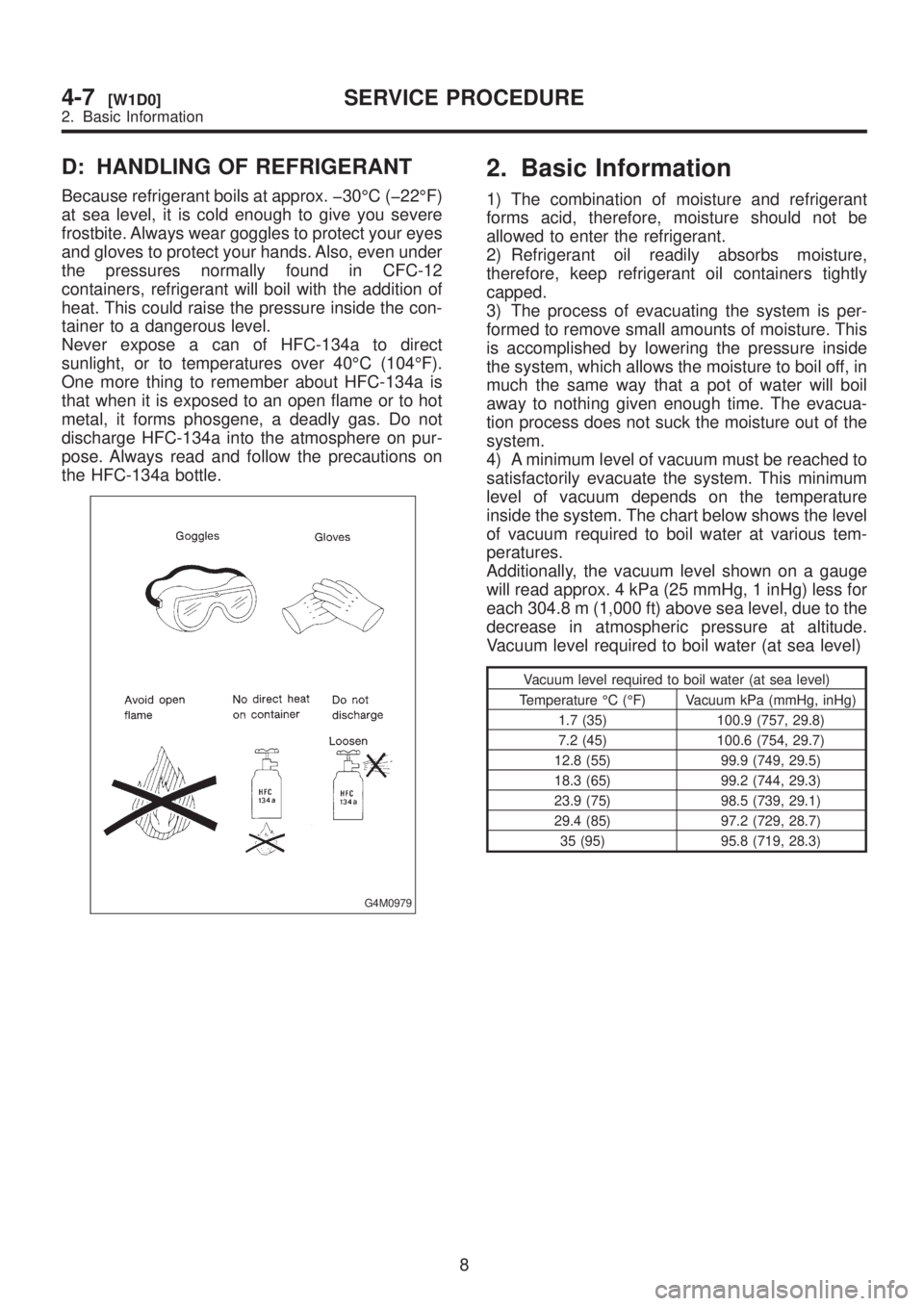
D: HANDLING OF REFRIGERANT
Because refrigerant boils at approx. þ30ÉC (þ22ÉF)
at sea level, it is cold enough to give you severe
frostbite. Always wear goggles to protect your eyes
and gloves to protect your hands. Also, even under
the pressures normally found in CFC-12
containers, refrigerant will boil with the addition of
heat. This could raise the pressure inside the con-
tainer to a dangerous level.
Never expose a can of HFC-134a to direct
sunlight, or to temperatures over 40ÉC (104ÉF).
One more thing to remember about HFC-134a is
that when it is exposed to an open flame or to hot
metal, it forms phosgene, a deadly gas. Do not
discharge HFC-134a into the atmosphere on pur-
pose. Always read and follow the precautions on
the HFC-134a bottle.
G4M0979
2. Basic Information
1) The combination of moisture and refrigerant
forms acid, therefore, moisture should not be
allowed to enter the refrigerant.
2) Refrigerant oil readily absorbs moisture,
therefore, keep refrigerant oil containers tightly
capped.
3) The process of evacuating the system is per-
formed to remove small amounts of moisture. This
is accomplished by lowering the pressure inside
the system, which allows the moisture to boil off, in
much the same way that a pot of water will boil
away to nothing given enough time. The evacua-
tion process does not suck the moisture out of the
system.
4) A minimum level of vacuum must be reached to
satisfactorily evacuate the system. This minimum
level of vacuum depends on the temperature
inside the system. The chart below shows the level
of vacuum required to boil water at various tem-
peratures.
Additionally, the vacuum level shown on a gauge
will read approx. 4 kPa (25 mmHg, 1 inHg) less for
each 304.8 m (1,000 ft) above sea level, due to the
decrease in atmospheric pressure at altitude.
Vacuum level required to boil water (at sea level)
Vacuum level required to boil water (at sea level)
Temperature ÉC (ÉF) Vacuum kPa (mmHg, inHg)
1.7 (35) 100.9 (757, 29.8)
7.2 (45) 100.6 (754, 29.7)
12.8 (55) 99.9 (749, 29.5)
18.3 (65) 99.2 (744, 29.3)
23.9 (75) 98.5 (739, 29.1)
29.4 (85) 97.2 (729, 28.7)
35 (95) 95.8 (719, 28.3)
8
4-7[W1D0]SERVICE PROCEDURE
2. Basic Information
Page 984 of 1456
3. Tools and Equipment
The following section provides information about
the tools and equipment that will be necessary to
properly service the A/C system.
Since equipment may vary slightly depending on
the manufacturer, it is important to always read and
follow the manufacturer's instructions.
CAUTION:
When working on vehicles with the HFC-134a
system, only use HFC-134a specified tools and
parts. Do not mix with CFC-12 tools and parts.
If HFC-134a and CFC-12 refrigerant or com-pressor oil is mixed, poor lubrication will result
and the compressor itself may be destroyed. In
order to help prevent mixing HFC-134a and
CFC-12 parts and liquid, the tool and screw
type and the type of service valves used are
different. The gas leak detectors for the HFC-
134a and CFC-12 systems must also not be
interchanged.
HFC-134a CFC-12
Tool & screw type Millimeter size Inch size
Valve type Quick joint type Screw-in type
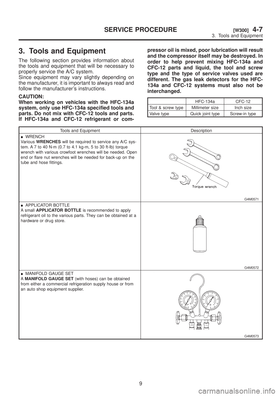
Tools and Equipment Description
IWRENCH
VariousWRENCHESwill be required to service any A/C sys-
tem. A 7 to 40 N´m (0.7 to 4.1 kg-m, 5 to 30 ft-lb) torque
wrench with various crowfoot wrenches will be needed. Open
end or flare nut wrenches will be needed for back-up on the
tube and hose fittings.
G4M0571
IAPPLICATOR BOTTLE
A smallAPPLICATOR BOTTLEis recommended to apply
refrigerant oil to the various parts. They can be obtained at a
hardware or drug store.
G4M0572
IMANIFOLD GAUGE SET
AMANIFOLD GAUGE SET(with hoses) can be obtained
from either a commercial refrigeration supply house or from
an auto shop equipment supplier.
G4M0573
9
[W300]4-7SERVICE PROCEDURE
3. Tools and Equipment