1999 SUBARU LEGACY light
[x] Cancel search: lightPage 1168 of 1456
2. Inspection and Replacement
Standards
A: VEHICLES WHICH BECOME
INVOLVED IN A COLLISION
If the vehicle equipped with an SRS airbag sys-
tem is damaged in a collision, the airbag sys-
tem parts must be checked and replaced in
accordance with the following standards:
IAfter faulty parts are replaced, the warning light
operation must be checked.
IWhen the ignition switch is turned ON, it lights
up for about 7 seconds and then it goes out for at
least 30 seconds.
IThe trouble code stored in memory must be
erased after the check.
B: AIRBAG MODULE (DRIVER AND
PASSENGER)
1. INSPECTION STANDARD
IThe vehicle damaged in a frontal collision
(regardless of whether or not airbag is deployed).
IThe designated trouble code is output during
self-diagnosis.
2. REPLACEMENT STANDARD
IAirbag is deployed.
IThe pad surface is scratched or cracked.
IHarness and/or connector is deformed or
cracked, their circuits are broken, lead wire is
exposed, etc.
IMounting bracket is cracked or deformed.
IThe module surface is fouled with foreign mat-
ter. (grease, oil, water, cleaning solvent, etc.)
IAirbag module dropped to the floor/ground.
IAirbag module determined as faulty during self-
diagnosis.
C: AIRBAG MODULE (SIDE)
1. INSPECTION STANDARD
IThe vehicle damaged in a side collision (regard-
less of whether or not airbag is deployed).
IThe designated trouble code is output during
self-diagnosis.
2. REPLACEMENT STANDARD
IAirbag is deployed.
IThe front seat assembly is dameged or
deformed.
IHarness and/or connector is deformed or
cracked, their circuits are broken, lead wire is
exposed, etc.
IMounting bracket is cracked or deformed.IAirbag module determined as faulty during self-
diagnosis.
D: MAIN HARNESS
1. INSPECTION STANDARD
IA vehicle damaged in a collision (regardless of
whether or not airbag is deployed).
IThe designated trouble code is output during
self-diagnosis.
2. REPLACEMENT STANDARD
IHarness circuit is broken, lead wire is exposed,
corrugated tube is cracked, etc.
IConnector is scratched or cracked.
IThe designated trouble code is output during
self-diagnosis.
E: AIRBAG CONTROL MODULE
1. INSPECTION STANDARD
IA vehicle damaged in a collision (regardless of
whether or not airbag is deployed).
IThe designated trouble code is output during
self-diagnosis.
2. REPLACEMENT STANDARD
IControl module is cracked or deformed.
IMounting bracket is cracked or deformed.
IConnector is scratched or cracked.
IControl module dropped to the floor/ground.
IControl module determined as faulty during
diagnostics.
IAirbag is deployed.
F: COMBINATION SWITCH
1. INSPECTION STANDARD
IA vehicle damaged in a collision (regardless of
whether or not airbag is deployed).
IThe designated trouble code is output during
self-diagnosis.
2. REPLACEMENT STANDARD
Combination switch or steering roll connector is
deformed or cracked.
6
5-5[W2A0]SERVICE PROCEDURE
2. Inspection and Replacement Standards
Page 1171 of 1456
3. Airbag Module
A: REMOVAL AND INSTALLATION
CAUTION:
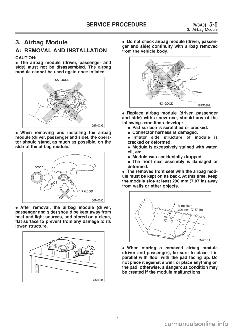
IThe airbag module (driver, passenger and
side) must not be disassembled. The airbag
module cannot be used again once inflated.
G5M0299
IWhen removing and installing the airbag
module (driver, passenger and side), the opera-
tor should stand, as much as possible, on the
side of the airbag module.
G5M0300
IAfter removal, the airbag module (driver,
passenger and side) should be kept away from
heat and light sources, and stored on a clean,
flat surface to prevent from any damage to its
lower structure.
G5M0301
IDo not check airbag module (driver, passen-
ger and side) continuity with airbag removed
from the vehicle body.
G5M0302
IReplace airbag module (driver, passenger
and side) with a new one, should any of the
following conditions develop:
IPad surface is scratched or cracked.
IConnector harness is damaged.
IInflator side structure of module is
cracked or deformed.
IModule is excessively stained with water,
oil, etc.
IModule was accidentally dropped.
IThe front seat assembly is damaged or
deformed.
IThe removed front seat with the airbag mod-
ule must be kept on its back. At this time, keep
the module side at least 200 mm (7.87 in) away
from walls or other objects.
B5M0515A
IWhen storing a removed airbag module
(driver and passenger), be sure to place it in
parallel with floor with the pad facing up. Do
not place it against a wall, or place anything on
the pad; otherwise, a dangerous condition may
be created if the module malfunctions.
9
[W3A0]5-5SERVICE PROCEDURE
3. Airbag Module
Page 1176 of 1456
5. Airbag Control Module
A: REMOVAL AND INSTALLATION
CAUTION:
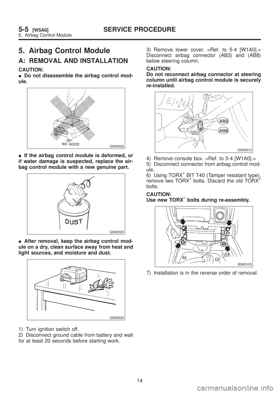
IDo not disassemble the airbag control mod-
ule.
G5M0322
IIf the airbag control module is deformed, or
if water damage is suspected, replace the air-
bag control module with a new genuine part.
G5M0323
IAfter removal, keep the airbag control mod-
ule on a dry, clean surface away from heat and
light sources, and moisture and dust.
G5M0324
1) Turn ignition switch off.
2) Disconnect ground cable from battery and wait
for at least 20 seconds before starting work.3) Remove lower cover.
Disconnect airbag connector (AB3) and (AB8)
below steering column.
CAUTION:
Do not reconnect airbag connector at steering
column until airbag control module is securely
re-installed.
G5M0312
4) Remove console box.
5) Disconnect connector from airbag control mod-
ule.
6) Using TORX
TBIT T40 (Tamper resistant type),
remove two TORXTbolts. Discard the old TORXT
bolts.
CAUTION:
Use new TORX
Tbolts during re-assembly.
B5M0105
7) Installation is in the reverse order of removal.
14
5-5[W5A0]SERVICE PROCEDURE
5. Airbag Control Module
Page 1215 of 1456
E: INSPECTION
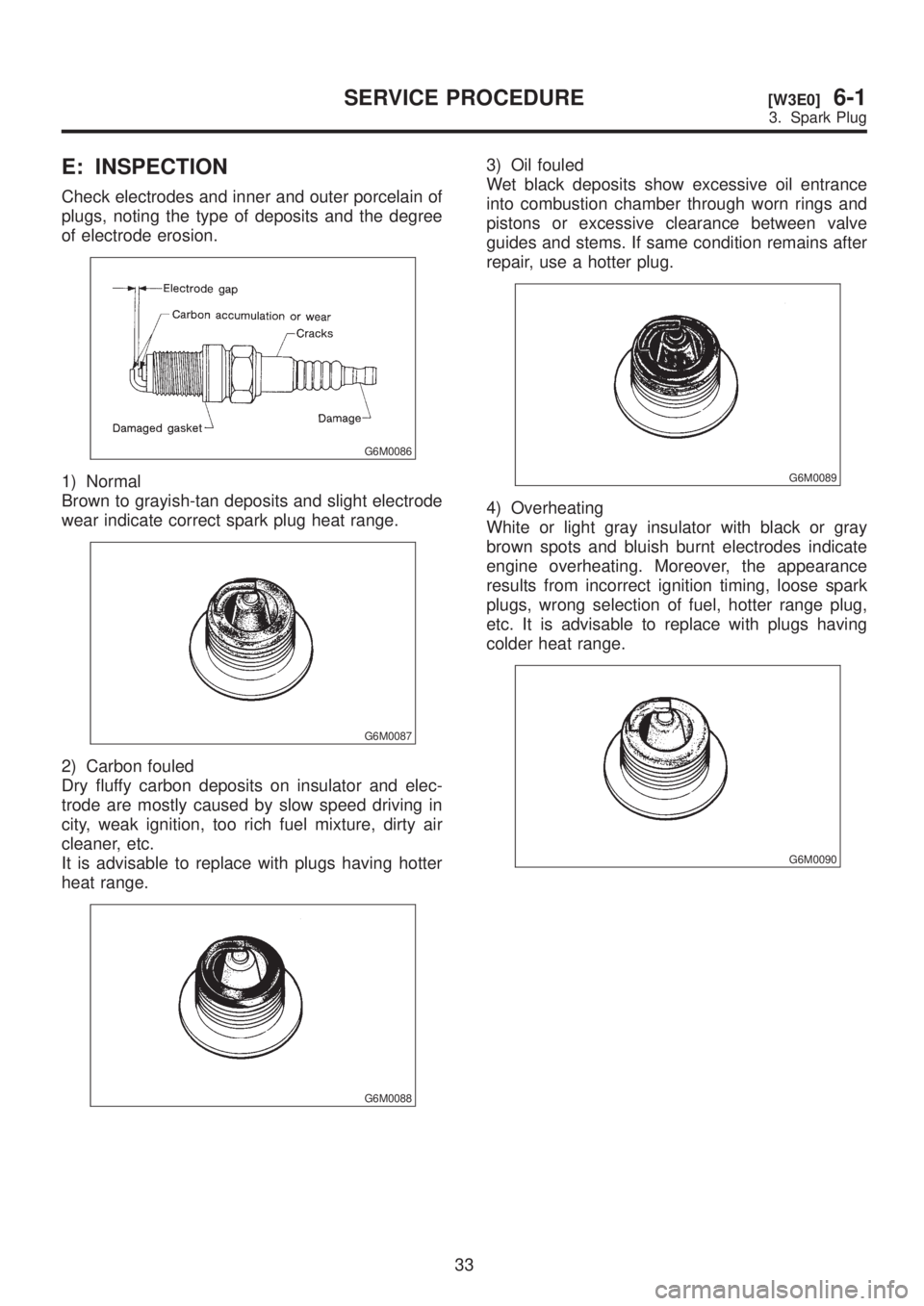
Check electrodes and inner and outer porcelain of
plugs, noting the type of deposits and the degree
of electrode erosion.
G6M0086
1) Normal
Brown to grayish-tan deposits and slight electrode
wear indicate correct spark plug heat range.
G6M0087
2) Carbon fouled
Dry fluffy carbon deposits on insulator and elec-
trode are mostly caused by slow speed driving in
city, weak ignition, too rich fuel mixture, dirty air
cleaner, etc.
It is advisable to replace with plugs having hotter
heat range.
G6M0088
3) Oil fouled
Wet black deposits show excessive oil entrance
into combustion chamber through worn rings and
pistons or excessive clearance between valve
guides and stems. If same condition remains after
repair, use a hotter plug.
G6M0089
4) Overheating
White or light gray insulator with black or gray
brown spots and bluish burnt electrodes indicate
engine overheating. Moreover, the appearance
results from incorrect ignition timing, loose spark
plugs, wrong selection of fuel, hotter range plug,
etc. It is advisable to replace with plugs having
colder heat range.
G6M0090
33
[W3E0]6-1SERVICE PROCEDURE
3. Spark Plug
Page 1226 of 1456
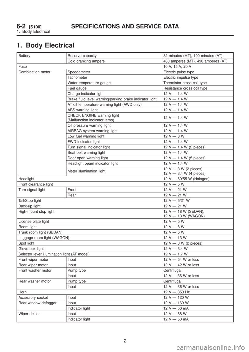
1. Body Electrical
Battery Reserve capacity 82 minutes (MT), 100 minutes (AT)
Cold cranking ampere 430 amperes (MT), 490 amperes (AT)
Fuse10 A, 15 A, 20 A
Combination meter Speedometer Electric pulse type
Tachometer Electric impulse type
Water temperature gauge Thermistor cross coil type
Fuel gauge Resistance cross coil type
Charge indicator light 12 V Ð 1.4 W
Brake fluid level warning/parking brake indicator light 12 V Ð 1.4 W
AT oil temperature warning light (AWD only) 12 V Ð 1.4 W
ABS warning light 12 V Ð 1.4 W
CHECK ENGINE warning light
(Malfunction indicator lamp)12 V Ð 1.4 W
Oil pressure warning light 12 V Ð 1.4 W
AIRBAG system warning light 12 V Ð 1.4 W
Low fuel warning light 12VÐ3W
FWD indicator light 12 V Ð 1.4 W
Turn signal indicator light 12 V Ð 1.4 W (2 pieces)
Seat belt warning light 12 V Ð 1.4 W
Door open warning light 12 V Ð 1.4 W (5 pieces)
Headlight beam indicator light 12 V Ð 1.4 W
Meter illumination light12VÐ3W(2pieces)
12 V Ð 3.4 W (4 pieces)
Headlight12 V Ð 60/55 W (Halogen)
Front clearance light 12VÐ5W
Turn signal light Front 12VÐ21W
Rear 12VÐ21W
Tail/Stop light12 V Ð 5/21 W
Back-up light12VÐ21W
High-mount stop light 12VÐ18W(SEDAN),
12VÐ13W(WAGON)
License plate light 12VÐ5W
Room light12VÐ8W
Trunk room light (SEDAN) 12VÐ5W
Luggage room light (WAGON) 12VÐ13W
Spot light12VÐ8W(2pieces)
Glove box light 12 V Ð 3.4 W
Selector lever illumination light (AT model) 12 V Ð 1.7 W
Front wiper motor Input 12VÐ54Worless
Rear wiper motor Input 12VÐ42Worless
Front washer motor Pump type Centrifugal
Input 12VÐ36Worless
Rear washer motor Pump type Centrifugal
Input 12VÐ36Worless
Horn12 V Ð 350 Hz
Accessory socket Input 12 V Ð 120 W
Rear window defogger Input 12 V Ð 160 W
Indicator light 12VÐ50mA
Wiper deicer Input 12VÐ88W
Indicator light 12VÐ50mA
2
6-2[S100]SPECIFICATIONS AND SERVICE DATA
1. Body Electrical
Page 1231 of 1456
4. Headlight
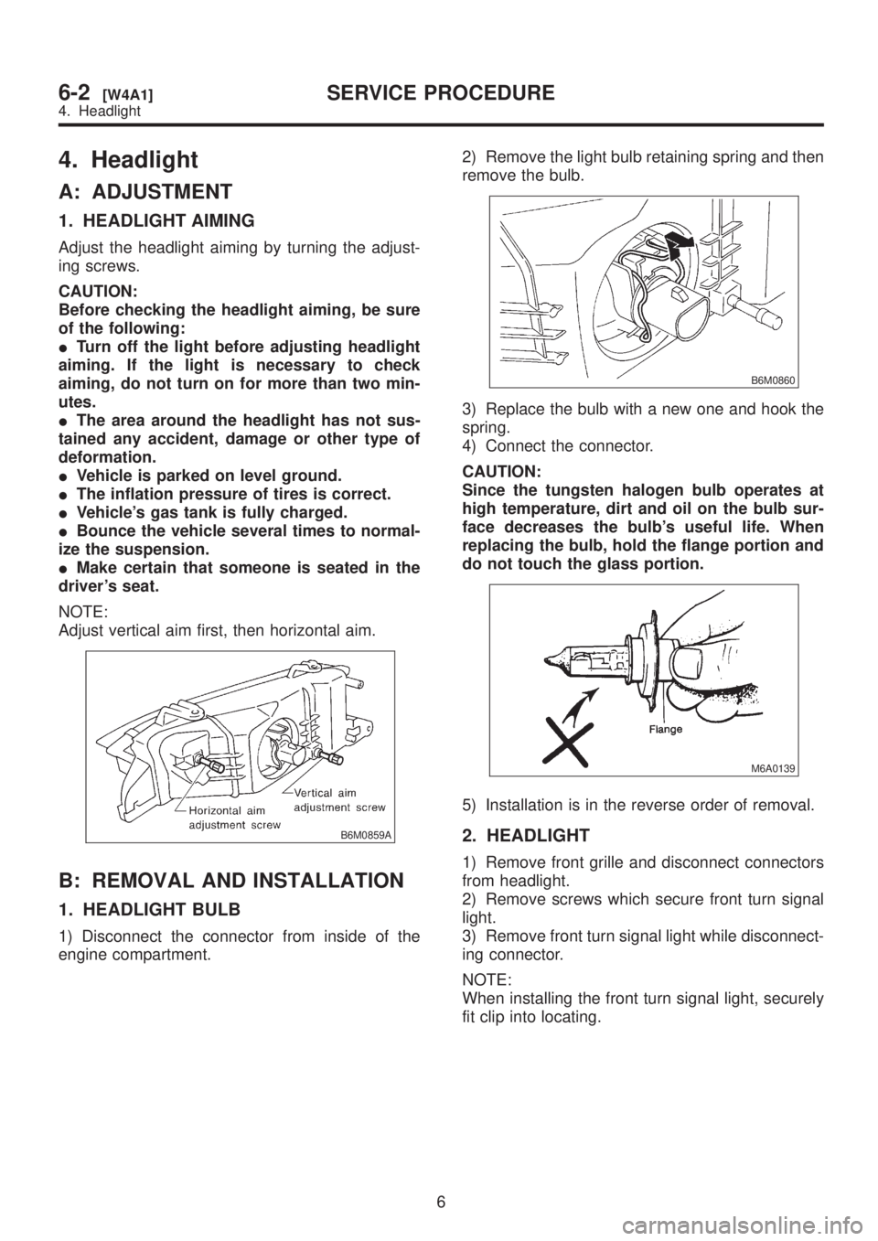
A: ADJUSTMENT
1. HEADLIGHT AIMING
Adjust the headlight aiming by turning the adjust-
ing screws.
CAUTION:
Before checking the headlight aiming, be sure
of the following:
ITurn off the light before adjusting headlight
aiming. If the light is necessary to check
aiming, do not turn on for more than two min-
utes.
IThe area around the headlight has not sus-
tained any accident, damage or other type of
deformation.
IVehicle is parked on level ground.
IThe inflation pressure of tires is correct.
IVehicle's gas tank is fully charged.
IBounce the vehicle several times to normal-
ize the suspension.
IMake certain that someone is seated in the
driver's seat.
NOTE:
Adjust vertical aim first, then horizontal aim.
B6M0859A
B: REMOVAL AND INSTALLATION
1. HEADLIGHT BULB
1) Disconnect the connector from inside of the
engine compartment.2) Remove the light bulb retaining spring and then
remove the bulb.
B6M0860
3) Replace the bulb with a new one and hook the
spring.
4) Connect the connector.
CAUTION:
Since the tungsten halogen bulb operates at
high temperature, dirt and oil on the bulb sur-
face decreases the bulb's useful life. When
replacing the bulb, hold the flange portion and
do not touch the glass portion.
M6A0139
5) Installation is in the reverse order of removal.
2. HEADLIGHT
1) Remove front grille and disconnect connectors
from headlight.
2) Remove screws which secure front turn signal
light.
3) Remove front turn signal light while disconnect-
ing connector.
NOTE:
When installing the front turn signal light, securely
fit clip into locating.
6
6-2[W4A1]SERVICE PROCEDURE
4. Headlight
Page 1232 of 1456
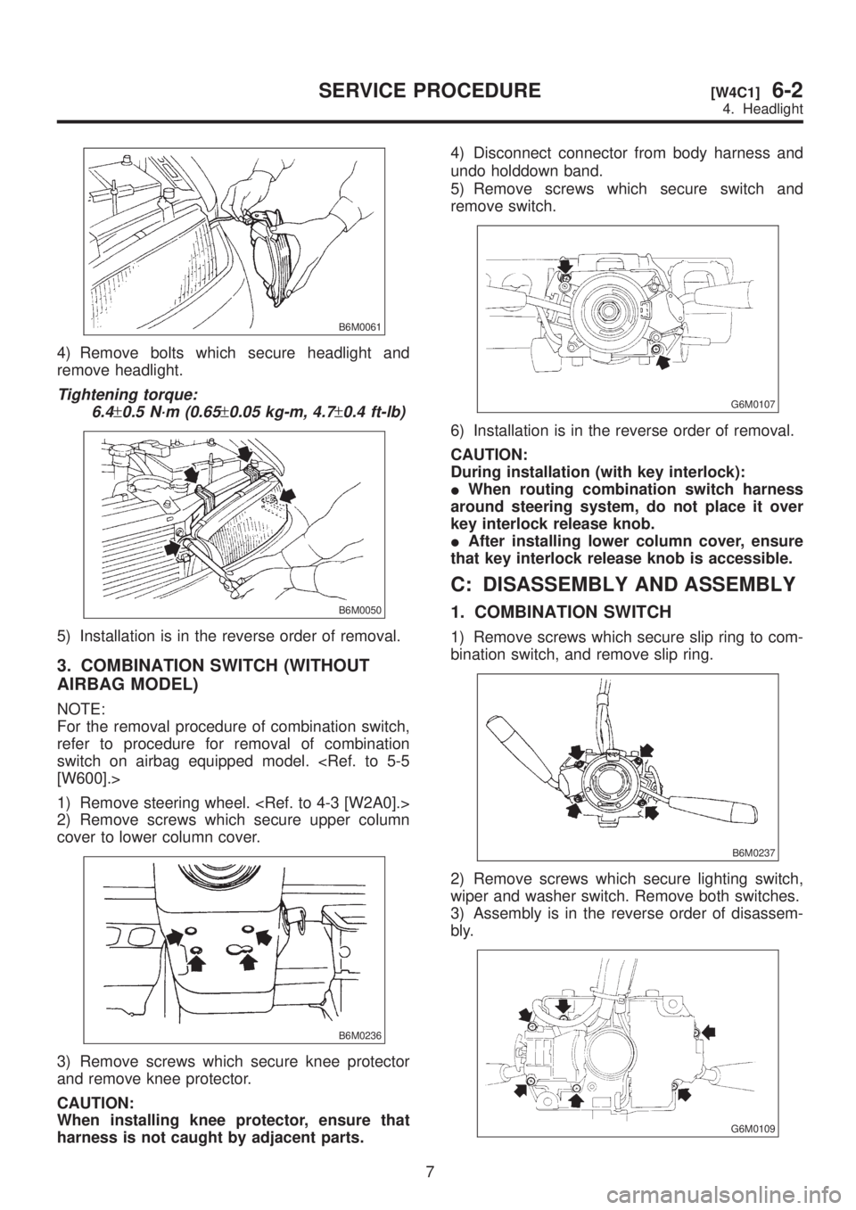
B6M0061
4) Remove bolts which secure headlight and
remove headlight.
Tightening torque:
6.4
±0.5 N´m (0.65±0.05 kg-m, 4.7±0.4 ft-lb)
B6M0050
5) Installation is in the reverse order of removal.
3. COMBINATION SWITCH (WITHOUT
AIRBAG MODEL)
NOTE:
For the removal procedure of combination switch,
refer to procedure for removal of combination
switch on airbag equipped model.
1) Remove steering wheel.
2) Remove screws which secure upper column
cover to lower column cover.
B6M0236
3) Remove screws which secure knee protector
and remove knee protector.
CAUTION:
When installing knee protector, ensure that
harness is not caught by adjacent parts.4) Disconnect connector from body harness and
undo holddown band.
5) Remove screws which secure switch and
remove switch.
G6M0107
6) Installation is in the reverse order of removal.
CAUTION:
During installation (with key interlock):
IWhen routing combination switch harness
around steering system, do not place it over
key interlock release knob.
IAfter installing lower column cover, ensure
that key interlock release knob is accessible.
C: DISASSEMBLY AND ASSEMBLY
1. COMBINATION SWITCH
1) Remove screws which secure slip ring to com-
bination switch, and remove slip ring.
B6M0237
2) Remove screws which secure lighting switch,
wiper and washer switch. Remove both switches.
3) Assembly is in the reverse order of disassem-
bly.
G6M0109
7
[W4C1]6-2SERVICE PROCEDURE
4. Headlight
Page 1233 of 1456
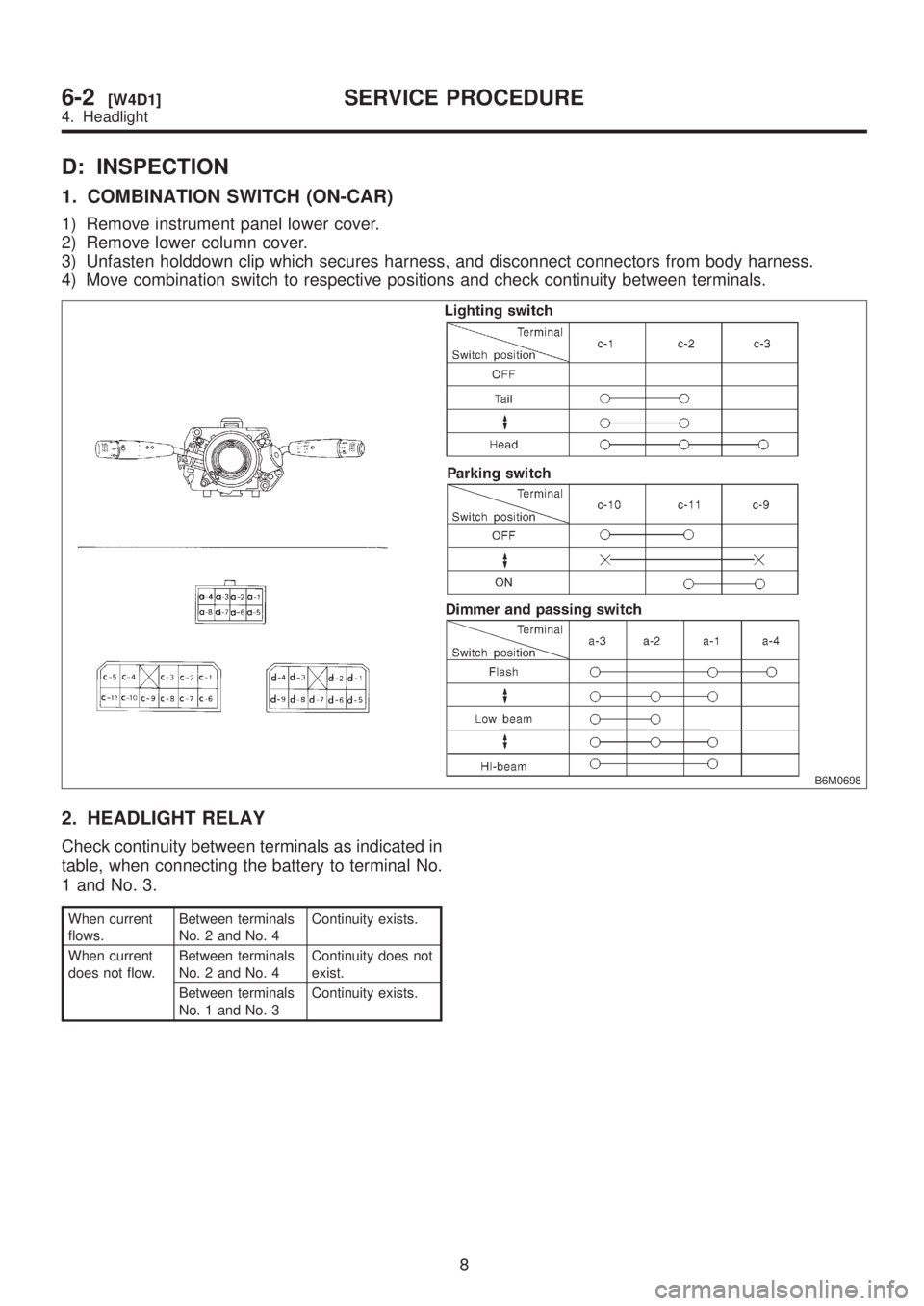
D: INSPECTION
1. COMBINATION SWITCH (ON-CAR)
1) Remove instrument panel lower cover.
2) Remove lower column cover.
3) Unfasten holddown clip which secures harness, and disconnect connectors from body harness.
4) Move combination switch to respective positions and check continuity between terminals.
B6M0698
2. HEADLIGHT RELAY
Check continuity between terminals as indicated in
table, when connecting the battery to terminal No.
1 and No. 3.
When current
flows.Between terminals
No. 2 and No. 4Continuity exists.
When current
does not flow.Between terminals
No. 2 and No. 4Continuity does not
exist.
Between terminals
No. 1 and No. 3Continuity exists.
8
6-2[W4D1]SERVICE PROCEDURE
4. Headlight