1999 SUBARU LEGACY light
[x] Cancel search: lightPage 1260 of 1456
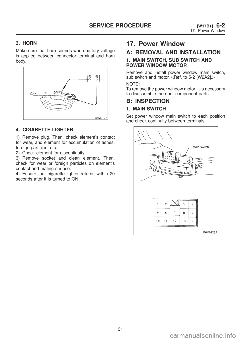
3. HORN
Make sure that horn sounds when battery voltage
is applied between connector terminal and horn
body.
B6M0127
4. CIGARETTE LIGHTER
1) Remove plug. Then, check element's contact
for wear, and element for accumulation of ashes,
foreign particles, etc.
2) Check element for discontinuity.
3) Remove socket and clean element. Then,
check for wear or foreign particles on element's
contact and mating surface.
4) Ensure that cigarette lighter returns within 20
seconds after it is turned to ON.
17. Power Window
A: REMOVAL AND INSTALLATION
1. MAIN SWITCH, SUB SWITCH AND
POWER WINDOW MOTOR
Remove and install power window main switch,
sub switch and motor.
NOTE:
To remove the power window motor, it is necessary
to disassemble the door component parts.
B: INSPECTION
1. MAIN SWITCH
Set power window main switch to each position
and check continuity between terminals.
B6M0128A
31
[W17B1]6-2SERVICE PROCEDURE
17. Power Window
Page 1267 of 1456
![SUBARU LEGACY 1999 Service Repair Manual 20. Sunroof
A: REMOVAL AND INSTALLATION
1. SUNROOF AND SUNROOF MOTOR
<Ref. to 5-1 [W1600].> as for removal and instal-
lation of sunroof system.
2. SUNROOF SWITCH
NOTE:
The sunroof switch is installed SUBARU LEGACY 1999 Service Repair Manual 20. Sunroof
A: REMOVAL AND INSTALLATION
1. SUNROOF AND SUNROOF MOTOR
<Ref. to 5-1 [W1600].> as for removal and instal-
lation of sunroof system.
2. SUNROOF SWITCH
NOTE:
The sunroof switch is installed](/manual-img/17/57435/w960_57435-1266.png)
20. Sunroof
A: REMOVAL AND INSTALLATION
1. SUNROOF AND SUNROOF MOTOR
lation of sunroof system.
2. SUNROOF SWITCH
NOTE:
The sunroof switch is installed in spot light body.
1) Pry spot light lens off using a screwdriver.
2) Remove screws which secure spot light body.
3) Remove spot light body while disconnecting
connectors.
4) Remove screw which secures sunroof switch,
and then remove sunroof switch.
B6M0141A
5) Installation is in the reverse order of removal.
B: INSPECTION
1. SUNROOF SWITCH
Set sunroof switch to each position and check con-
tinuity between terminals as indicated in table
below:
B6M0142A
B6M0861A
37
[W20B1]6-2SERVICE PROCEDURE
20. Sunroof
Page 1269 of 1456
21. Radio, Speaker and
Antenna
A: REMOVAL AND INSTALLATION
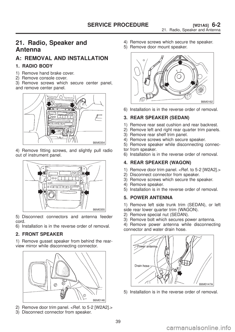
1. RADIO BODY
1) Remove hand brake cover.
2) Remove console cover.
3) Remove screws which secure center panel,
and remove center panel.
B6M0354
4) Remove fitting screws, and slightly pull radio
out of instrument panel.
B6M0355
5) Disconnect connectors and antenna feeder
cord.
6) Installation is in the reverse order of removal.
2. FRONT SPEAKER
1) Remove gusset speaker from behind the rear-
view mirror while disconnecting connector.
B6M0146
2) Remove door trim panel.
3) Disconnect connector from speaker.4) Remove screws which secure the speaker.
5) Remove door mount speaker.
B6M0162
6) Installation is in the reverse order of removal.
3. REAR SPEAKER (SEDAN)
1) Remove rear seat cushion and rear backrest.
2) Remove left and right rear quarter trim panels.
3) Remove rear shelf trim panel.
4) Remove screws which secure speaker.
5) Remove speaker while disconnecting connec-
tor from speaker.
6) Installation is in the reverse order of removal.
4. REAR SPEAKER (WAGON)
1) Remove door trim panel.
2) Disconnect connector from speaker.
3) Remove screws which secure the speaker.
4) Remove speaker.
5) Installation is in the reverse order of removal.
5. POWER ANTENNA
1) Remove left side trunk trim (SEDAN), or left
side rear lower quarter trim (WAGON).
2) Remove special nut (SEDAN).
3) Remove bolt which secures power antenna.
4) Remove power antenna while disconnecting
connector and water drain hose.
B6M0147A
5) Installation is in the reverse order of removal.
39
[W21A5]6-2SERVICE PROCEDURE
21. Radio, Speaker and Antenna
Page 1273 of 1456
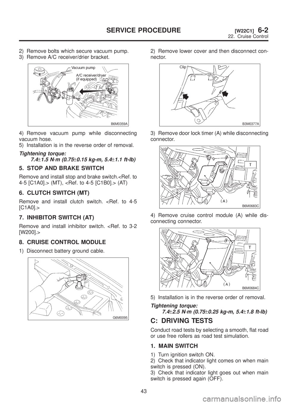
2) Remove bolts which secure vacuum pump.
3) Remove A/C receiver/drier bracket.
B6M0359A
4) Remove vacuum pump while disconnecting
vacuum hose.
5) Installation is in the reverse order of removal.
Tightening torque:
7.4
±1.5 N´m (0.75±0.15 kg-m, 5.4±1.1 ft-lb)
5. STOP AND BRAKE SWITCH
Remove and install stop and brake switch.
6. CLUTCH SWITCH (MT)
Remove and install clutch switch.
7. INHIBITOR SWITCH (AT)
Remove and install inhibitor switch.
8. CRUISE CONTROL MODULE
1) Disconnect battery ground cable.
G6M0095
2) Remove lower cover and then disconnect con-
nector.
B3M0377A
3) Remove door lock timer (A) while disconnecting
connector.
B6M0683C
4) Remove cruise control module (A) while dis-
connecting connector.
B6M0684C
5) Installation is in the reverse order of removal.
Tightening torque:
7.4
±2.5 N´m (0.75±0.25 kg-m, 5.4±1.8 ft-lb)
C: DRIVING TESTS
Conduct road tests by selecting a smooth, flat road
or use free rollers as road test simulation.
1. MAIN SWITCH
1) Turn ignition switch ON.
2) Check that indicator light comes on when main
switch is pressed (ON).
3) Check that indicator light goes out when main
switch is pressed again (OFF).
43
[W22C1]6-2SERVICE PROCEDURE
22. Cruise Control
Page 1274 of 1456
4) Turn ignition switch OFF with main switch ON
(which is indicated by illumination.).
5) Turn ignition switch ON again to ensure that
indicator light remains OFF.
2. COMMAND SWITCH
1) Check that command switch is properly set in
ªSET/COASTº, ªRESUME/ACCELº or ªCANCELº
mode.
2) Also check that command switch returns to the
original position when released.
3. CONSTANT SPEED TEST
1) Turn main switch ON.
2) Drive vehicle at speed greater than 40 km/h (25
MPH).
3) Press command switch to set in ªSET/COASTº
mode.
4) Ensure that vehicle is maintained at the speed
set when command switch was pressed.
4. ACCELERATION TEST
1) Set vehicle speed at speed greater than 40
km/h (25 MPH).
2) Ensure that vehicle continues to accelerate
while holding command switch in RESUME/
ACCEL mode, and that vehicle maintains that
optional speed when command switch is released.
5. DECELERATION TEST
1) Set vehicle speed at optional speed greater
than 40 km/h (25 MPH).
2) Ensure that vehicle continues to decelerate
while holding command switch in SET/COAST
mode, and that it maintains that optional speed
when command switch is released.
NOTE:
When vehicle speed reaches the lower speed limit
of 30 km/h (19 MPH) during deceleration, cruise
control will be released.
23. Security System
A: REMOVAL AND INSTALLATION
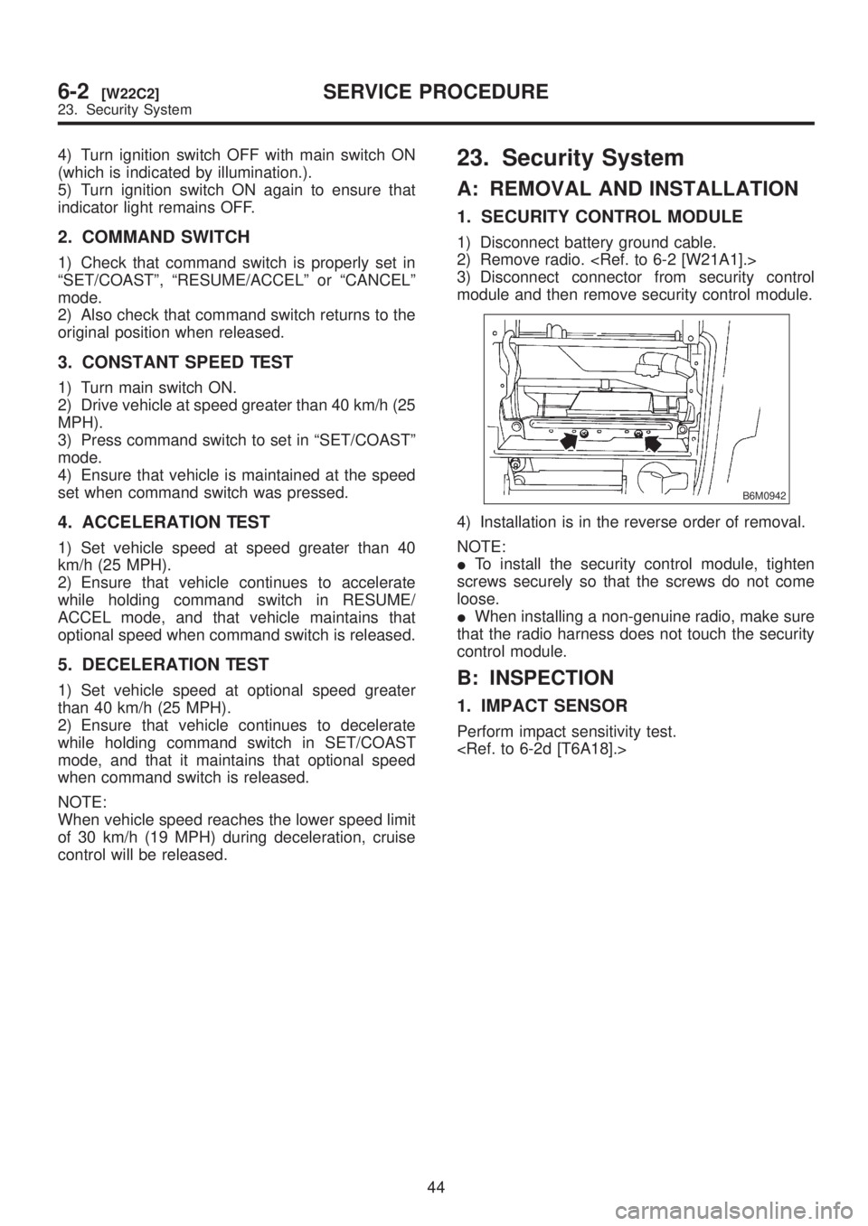
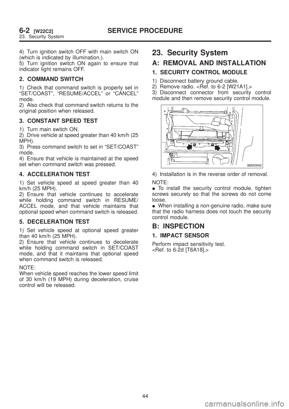
1. SECURITY CONTROL MODULE
1) Disconnect battery ground cable.
2) Remove radio.
3) Disconnect connector from security control
module and then remove security control module.
B6M0942
4) Installation is in the reverse order of removal.
NOTE:
ITo install the security control module, tighten
screws securely so that the screws do not come
loose.
IWhen installing a non-genuine radio, make sure
that the radio harness does not touch the security
control module.
B: INSPECTION
1. IMPACT SENSOR
Perform impact sensitivity test.
44
6-2[W22C2]SERVICE PROCEDURE
23. Security System
Page 1275 of 1456
4) Turn ignition switch OFF with main switch ON
(which is indicated by illumination.).
5) Turn ignition switch ON again to ensure that
indicator light remains OFF.
2. COMMAND SWITCH
1) Check that command switch is properly set in
ªSET/COASTº, ªRESUME/ACCELº or ªCANCELº
mode.
2) Also check that command switch returns to the
original position when released.
3. CONSTANT SPEED TEST
1) Turn main switch ON.
2) Drive vehicle at speed greater than 40 km/h (25
MPH).
3) Press command switch to set in ªSET/COASTº
mode.
4) Ensure that vehicle is maintained at the speed
set when command switch was pressed.
4. ACCELERATION TEST
1) Set vehicle speed at speed greater than 40
km/h (25 MPH).
2) Ensure that vehicle continues to accelerate
while holding command switch in RESUME/
ACCEL mode, and that vehicle maintains that
optional speed when command switch is released.
5. DECELERATION TEST
1) Set vehicle speed at optional speed greater
than 40 km/h (25 MPH).
2) Ensure that vehicle continues to decelerate
while holding command switch in SET/COAST
mode, and that it maintains that optional speed
when command switch is released.
NOTE:
When vehicle speed reaches the lower speed limit
of 30 km/h (19 MPH) during deceleration, cruise
control will be released.
23. Security System
A: REMOVAL AND INSTALLATION
1. SECURITY CONTROL MODULE
1) Disconnect battery ground cable.
2) Remove radio.
3) Disconnect connector from security control
module and then remove security control module.
B6M0942
4) Installation is in the reverse order of removal.
NOTE:
ITo install the security control module, tighten
screws securely so that the screws do not come
loose.
IWhen installing a non-genuine radio, make sure
that the radio harness does not touch the security
control module.
B: INSPECTION
1. IMPACT SENSOR
Perform impact sensitivity test.
44
6-2[W22C2]SERVICE PROCEDURE
23. Security System
Page 1281 of 1456
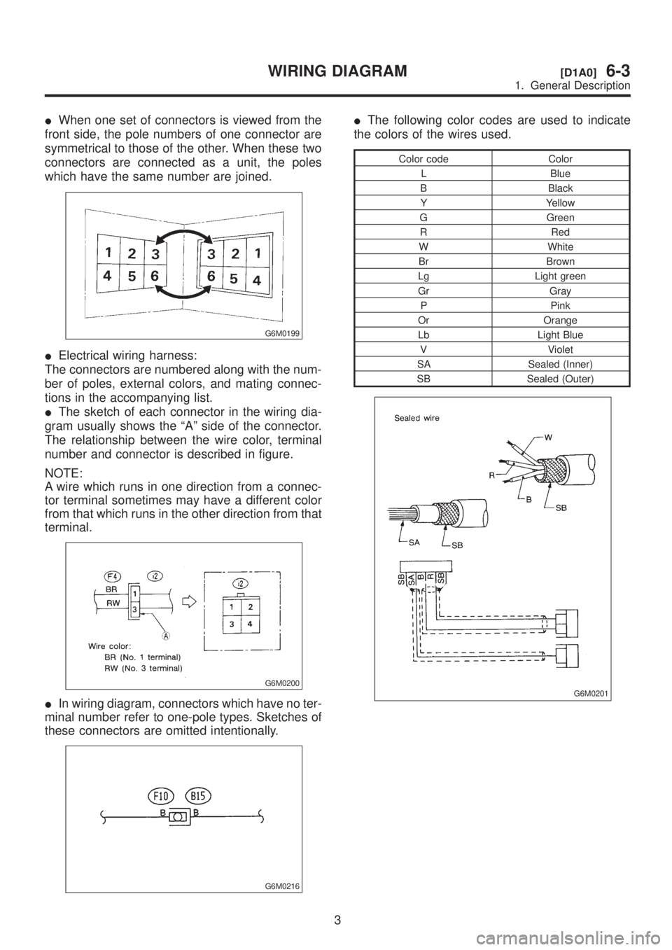
IWhen one set of connectors is viewed from the
front side, the pole numbers of one connector are
symmetrical to those of the other. When these two
connectors are connected as a unit, the poles
which have the same number are joined.
G6M0199
IElectrical wiring harness:
The connectors are numbered along with the num-
ber of poles, external colors, and mating connec-
tions in the accompanying list.
IThe sketch of each connector in the wiring dia-
gram usually shows the ªAº side of the connector.
The relationship between the wire color, terminal
number and connector is described in figure.
NOTE:
A wire which runs in one direction from a connec-
tor terminal sometimes may have a different color
from that which runs in the other direction from that
terminal.
G6M0200
IIn wiring diagram, connectors which have no ter-
minal number refer to one-pole types. Sketches of
these connectors are omitted intentionally.
G6M0216
IThe following color codes are used to indicate
the colors of the wires used.
Color code Color
L Blue
B Black
Y Yellow
G Green
R Red
W White
Br Brown
Lg Light green
Gr Gray
P Pink
Or Orange
Lb Light Blue
V Violet
SA Sealed (Inner)
SB Sealed (Outer)
G6M0201
3
[D1A0]6-3WIRING DIAGRAM
1. General Description
Page 1284 of 1456
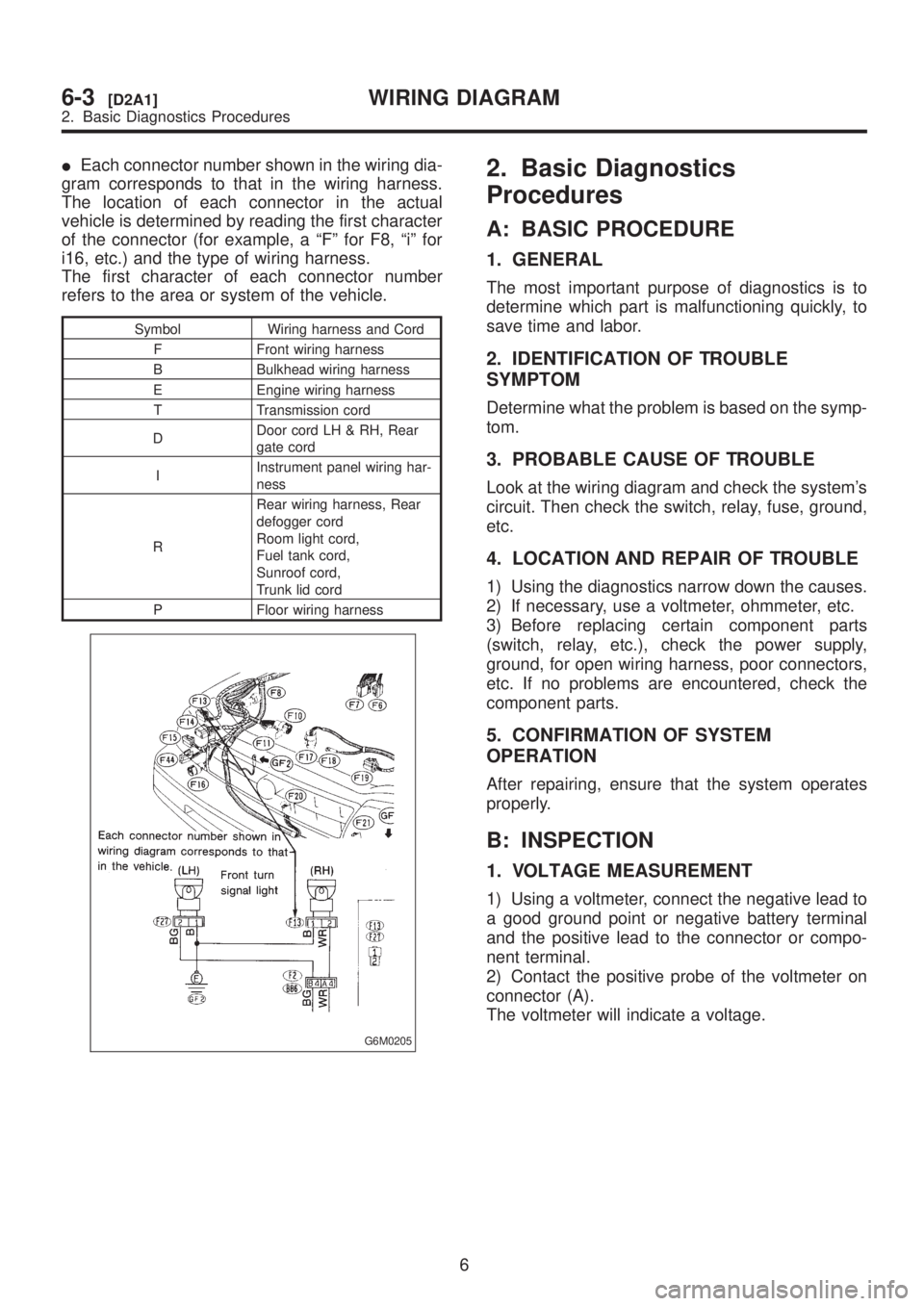
IEach connector number shown in the wiring dia-
gram corresponds to that in the wiring harness.
The location of each connector in the actual
vehicle is determined by reading the first character
of the connector (for example, a ªFº for F8, ªiº for
i16, etc.) and the type of wiring harness.
The first character of each connector number
refers to the area or system of the vehicle.
Symbol Wiring harness and Cord
F Front wiring harness
B Bulkhead wiring harness
E Engine wiring harness
T Transmission cord
DDoor cord LH & RH, Rear
gate cord
IInstrument panel wiring har-
ness
RRear wiring harness, Rear
defogger cord
Room light cord,
Fuel tank cord,
Sunroof cord,
Trunk lid cord
P Floor wiring harness
G6M0205
2. Basic Diagnostics
Procedures
A: BASIC PROCEDURE
1. GENERAL
The most important purpose of diagnostics is to
determine which part is malfunctioning quickly, to
save time and labor.
2. IDENTIFICATION OF TROUBLE
SYMPTOM
Determine what the problem is based on the symp-
tom.
3. PROBABLE CAUSE OF TROUBLE
Look at the wiring diagram and check the system's
circuit. Then check the switch, relay, fuse, ground,
etc.
4. LOCATION AND REPAIR OF TROUBLE
1) Using the diagnostics narrow down the causes.
2) If necessary, use a voltmeter, ohmmeter, etc.
3) Before replacing certain component parts
(switch, relay, etc.), check the power supply,
ground, for open wiring harness, poor connectors,
etc. If no problems are encountered, check the
component parts.
5. CONFIRMATION OF SYSTEM
OPERATION
After repairing, ensure that the system operates
properly.
B: INSPECTION
1. VOLTAGE MEASUREMENT
1) Using a voltmeter, connect the negative lead to
a good ground point or negative battery terminal
and the positive lead to the connector or compo-
nent terminal.
2) Contact the positive probe of the voltmeter on
connector (A).
The voltmeter will indicate a voltage.
6
6-3[D2A1]WIRING DIAGRAM
2. Basic Diagnostics Procedures