Page 208 of 1456

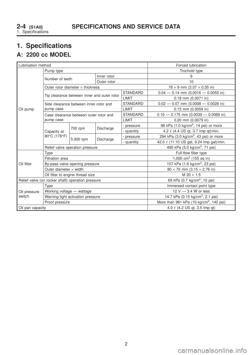
1. Specifications
A: 2200 cc MODEL
Lubrication methodForced lubrication
Oil pumpPump type Trochoid type
Number of teethInner rotor 9
Outer rotor 10
Outer rotor diameter´thickness 78´9 mm (3.07´0.35 in)
Tip clearance between inner and outer rotorSTANDARD 0.04 Ð 0.14 mm (0.0016 Ð 0.0055 in)
LIMIT 0.18 mm (0.0071 in)
Side clearance between inner rotor and
pump caseSTANDARD 0.02 Ð 0.07 mm (0.0008 Ð 0.0028 in)
LIMIT 0.15 mm (0.0059 in)
Case clearance between outer rotor and
pump caseSTANDARD 0.10 Ð 0.175 mm (0.0039 Ð 0.0069 in)
LIMIT 0.20 mm (0.0079 in)
Capacity at
80ÉC (176ÉF)700 rpm Discharge- pressure 98 kPa (1.0 kg/cm
2, 14 psi) or more
- quantity 4.2(4.4 US qt, 3.7 Imp qt)/min.
5,000 rpm Discharge- pressure 294 kPa (3.0 kg/cm
2, 43 psi) or more
- quantity 42.0(11.10 US gal, 9.24 Imp gal)/min.
Relief valve operation pressure 490 kPa (5.0 kg/cm
2, 71 psi)
Oil filterTypeFull-flow filter type
Filtration area 1,000 cm
2(155 sq in)
By-pass valve opening pressure 157 kPa (1.6 kg/cm2, 23 psi)
Outer diameter´width 80´70 mm (3.15´2.76 in)
Oil filter to engine thread size M 20´1.5
Relief valve (on rocker shaft) operation pressure 69 kPa (0.7 kg/cm
2, 10 psi)
Oil pressure
switchType Immersed contact point type
Working voltage Ð wattage 12 V Ð 3.4 W or less
Warning light activation pressure 14.7 kPa (0.15 kg/cm
2, 2.1 psi)
Proof pressure More than 981 kPa (10 kg/cm2, 142 psi)
Oil pan capacity4.0(4.2 US qt, 3.5 Imp qt)
2
2-4[S1A0]SPECIFICATIONS AND SERVICE DATA
1. Specifications
Page 209 of 1456

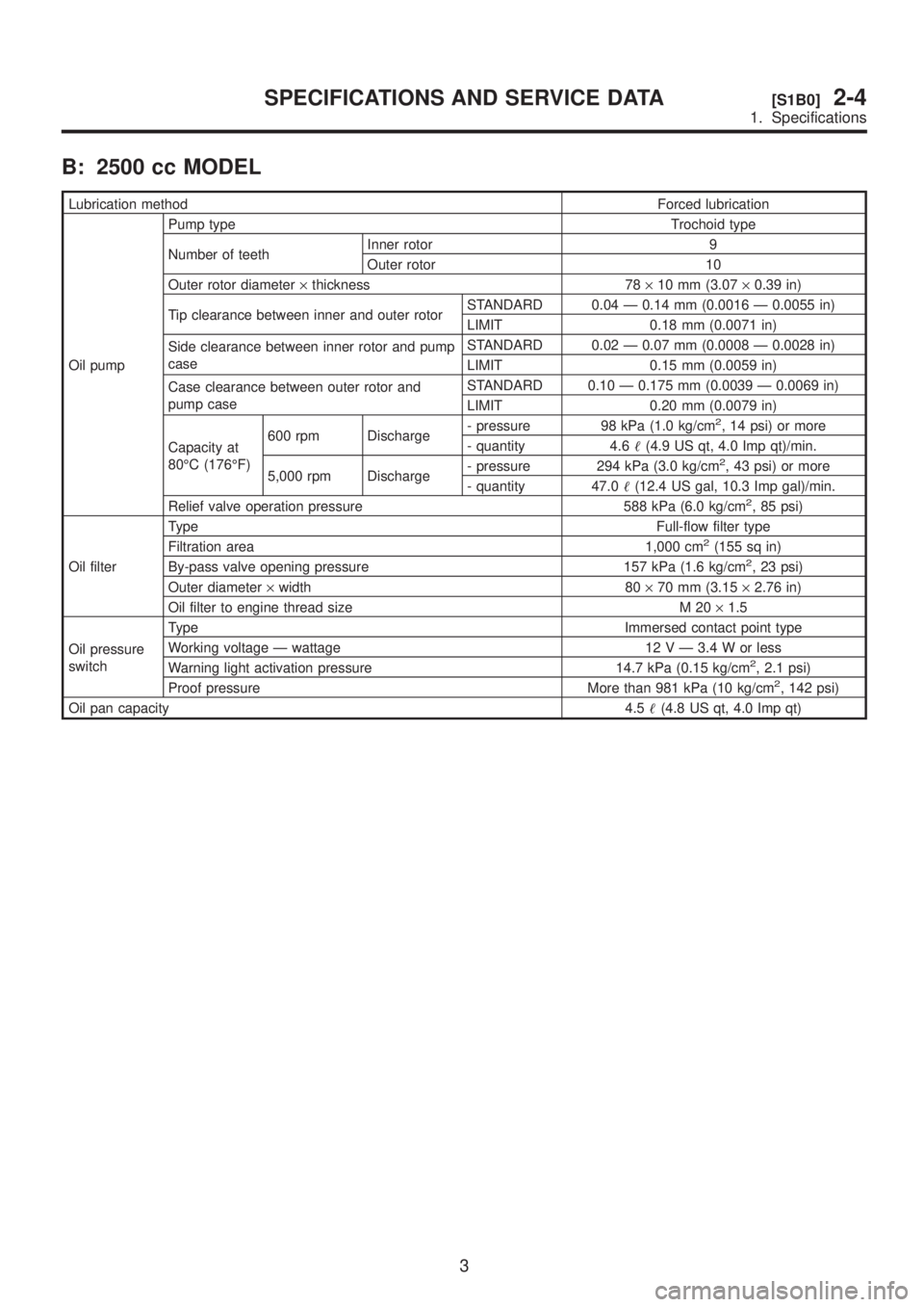
B: 2500 cc MODEL
Lubrication methodForced lubrication
Oil pumpPump type Trochoid type
Number of teethInner rotor 9
Outer rotor 10
Outer rotor diameter´thickness 78´10 mm (3.07´0.39 in)
Tip clearance between inner and outer rotorSTANDARD 0.04 Ð 0.14 mm (0.0016 Ð 0.0055 in)
LIMIT 0.18 mm (0.0071 in)
Side clearance between inner rotor and pump
caseSTANDARD 0.02 Ð 0.07 mm (0.0008 Ð 0.0028 in)
LIMIT 0.15 mm (0.0059 in)
Case clearance between outer rotor and
pump caseSTANDARD 0.10 Ð 0.175 mm (0.0039 Ð 0.0069 in)
LIMIT 0.20 mm (0.0079 in)
Capacity at
80ÉC (176ÉF)600 rpm Discharge- pressure 98 kPa (1.0 kg/cm
2, 14 psi) or more
- quantity 4.6(4.9 US qt, 4.0 Imp qt)/min.
5,000 rpm Discharge- pressure 294 kPa (3.0 kg/cm
2, 43 psi) or more
- quantity 47.0(12.4 US gal, 10.3 Imp gal)/min.
Relief valve operation pressure 588 kPa (6.0 kg/cm
2, 85 psi)
Oil filterTypeFull-flow filter type
Filtration area 1,000 cm
2(155 sq in)
By-pass valve opening pressure 157 kPa (1.6 kg/cm2, 23 psi)
Outer diameter´width 80´70 mm (3.15´2.76 in)
Oil filter to engine thread size M 20´1.5
Oil pressure
switchType Immersed contact point type
Working voltage Ð wattage 12 V Ð 3.4 W or less
Warning light activation pressure 14.7 kPa (0.15 kg/cm
2, 2.1 psi)
Proof pressure More than 981 kPa (10 kg/cm2, 142 psi)
Oil pan capacity4.5(4.8 US qt, 4.0 Imp qt)
3
[S1B0]2-4SPECIFICATIONS AND SERVICE DATA
1. Specifications
Page 227 of 1456

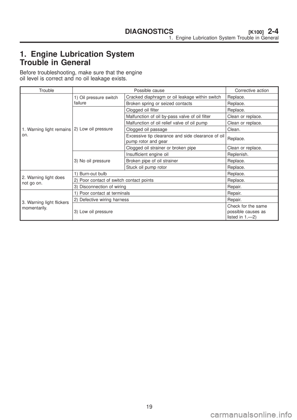
1. Engine Lubrication System
Trouble in General
Before troubleshooting, make sure that the engine
oil level is correct and no oil leakage exists.
Trouble Possible cause Corrective action
1. Warning light remains
on.1) Oil pressure switch
failureCracked diaphragm or oil leakage within switch Replace.
Broken spring or seized contacts Replace.
2) Low oil pressureClogged oil filter Replace.
Malfunction of oil by-pass valve of oil filter Clean or replace.
Malfunction of oil relief valve of oil pump Clean or replace.
Clogged oil passage Clean.
Excessive tip clearance and side clearance of oil
pump rotor and gearReplace.
Clogged oil strainer or broken pipe Clean or replace.
3) No oil pressureInsufficient engine oil Replenish.
Broken pipe of oil strainer Replace.
Stuck oil pump rotor Replace.
2. Warning light does
not go on.1) Burn-out bulb Replace.
2) Poor contact of switch contact points Replace.
3) Disconnection of wiring Repair.
3. Warning light flickers
momentarily.1) Poor contact at terminals Repair.
2) Defective wiring harness Repair.
3) Low oil pressureCheck for the same
possible causes as
listed in 1.Ð2)
19
[K100]2-4DIAGNOSTICS
1. Engine Lubrication System Trouble in General
Page 246 of 1456
5) Disconnect connectors of radiator main fan (A)
and sub fan (B) motors.
B2M2035A
6) Disconnect radiator outlet hose from thermostat
cover.
H2M2515
7) Lower the vehicle.
8) Remove reservoir tank.
S2M0028
9) Disconnect ATF cooler hoses from radiator. (AT
vehicles only)
S2M0029
10) Remove V-belt covers.
B2M2307
11) Disconnect radiator inlet hose from radiator.
S2M0031
12) Remove radiator upper brackets.
B2M0320
13) While slightly lifting radiator, slide it to left.
14) Lift radiator up and away from vehicle.
B2M2323
15
[W4A0]2-5SERVICE PROCEDURE
4. Radiator
Page 419 of 1456

5) Remove release lever retainer spring from
release lever pivot with a screwdriver by accessing
it through clutch housing release lever hole. Then
remove release lever.
B2M1258A
B: INSPECTION
1. RELEASE BEARING
CAUTION:
Since this bearing is grease sealed and is of a
nonlubrication type, do not wash with gasoline
or any solvent when servicing the clutch.
1) Check the bearing for smooth movement by
applying force in the radial direction.
Radial direction stroke:
FWD; Approx.
1.0 mm (0.039 in)
AWD; Approx.
1.4 mm (0.055 in)
B2M0173A
2) Check the bearing for smooth rotation by apply-
ing pressure in the thrust direction.
G2M0240
3) Check wear and damage of bearing case sur-
face contacting with lever.
2. RELEASE LEVER
1) Check lever pivot portion and the point of con-
tact with release bearing case for wear.
G2M0241
C: INSTALLATION
CAUTION:
Before or during assembling, lubricate the fol-
lowing points with a light coat of grease.
IInner groove of release bearing
IContact surface of lever and pivot
IContact surface of lever and bearing
ITransmission main shaft spline (Use grease
containing molybdenum disulphide.)
9
[W3C0]2-10SERVICE PROCEDURE
3. Release Bearing and Lever
Page 421 of 1456

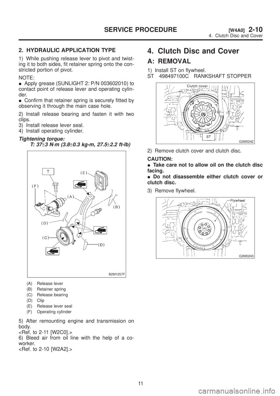
2. HYDRAULIC APPLICATION TYPE
1) While pushing release lever to pivot and twist-
ing it to both sides, fit retainer spring onto the con-
stricted portion of pivot.
NOTE:
IApply grease (SUNLIGHT 2: P/N 003602010) to
contact point of release lever and operating cylin-
der.
IConfirm that retainer spring is securely fitted by
observing it through the main case hole.
2) Install release bearing and fasten it with two
clips.
3) Install release lever seal.
4) Install operating cylinder.
Tightening torque:
T: 3 7
±3 N´m (3.8±0.3 kg-m, 27.5±2.2 ft-lb)
B2M1257F
(A) Release lever
(B) Retainer spring
(C) Release bearing
(D) Clip
(E) Release lever seal
(F) Operating cylinder
5) After remounting engine and transmission on
body.
6) Bleed air from oil line with the help of a co-
worker.
4. Clutch Disc and Cover
A: REMOVAL
1) Install ST on flywheel.
ST 498497100C RANKSHAFT STOPPER
G2M0242
2) Remove clutch cover and clutch disc.
CAUTION:
ITake care not to allow oil on the clutch disc
facing.
IDo not disassemble either clutch cover or
clutch disc.
3) Remove flywheel.
G2M0243
11
[W4A0]2-10SERVICE PROCEDURE
4. Clutch Disc and Cover
Page 422 of 1456

2. HYDRAULIC APPLICATION TYPE
1) While pushing release lever to pivot and twist-
ing it to both sides, fit retainer spring onto the con-
stricted portion of pivot.
NOTE:
IApply grease (SUNLIGHT 2: P/N 003602010) to
contact point of release lever and operating cylin-
der.
IConfirm that retainer spring is securely fitted by
observing it through the main case hole.
2) Install release bearing and fasten it with two
clips.
3) Install release lever seal.
4) Install operating cylinder.
Tightening torque:
T: 3 7
±3 N´m (3.8±0.3 kg-m, 27.5±2.2 ft-lb)
B2M1257F
(A) Release lever
(B) Retainer spring
(C) Release bearing
(D) Clip
(E) Release lever seal
(F) Operating cylinder
5) After remounting engine and transmission on
body.
6) Bleed air from oil line with the help of a co-
worker.
4. Clutch Disc and Cover
A: REMOVAL
1) Install ST on flywheel.
ST 498497100C RANKSHAFT STOPPER
G2M0242
2) Remove clutch cover and clutch disc.
CAUTION:
ITake care not to allow oil on the clutch disc
facing.
IDo not disassemble either clutch cover or
clutch disc.
3) Remove flywheel.
G2M0243
11
[W4A0]2-10SERVICE PROCEDURE
4. Clutch Disc and Cover
Page 426 of 1456
5. Operating Cylinder
A: REMOVAL AND INSTALLATION
1) Remove air chamber.
B2M1265
2) Remove clutch hose from operating cylinder.
CAUTION:
Cover hose joint to prevent brake fluid from
flowing out.
B2M1179B
3) Remove operating cylinder from transmission.
B2M1263
4) Installation is in the reverse order of removal.
NOTE:
Before installing operating cylinder, apply grease
(SUNLIGHT 2: P/N 003602010) to contact point of
release lever and operating cylinder.
Tightening torque:
T1: 18
±3 N´m (1.8±0.3 kg-m, 13.0±2.2 ft-lb)
T2: 37
±3 N´m (3.8±0.3 kg-m, 27.5±2.2 ft-lb)
B2M1179C
5) After bleeding air from operating cylinder,
ensure that clutch operates properly.
15
[W5A0]2-10SERVICE PROCEDURE
5. Operating Cylinder