Page 127 of 2267
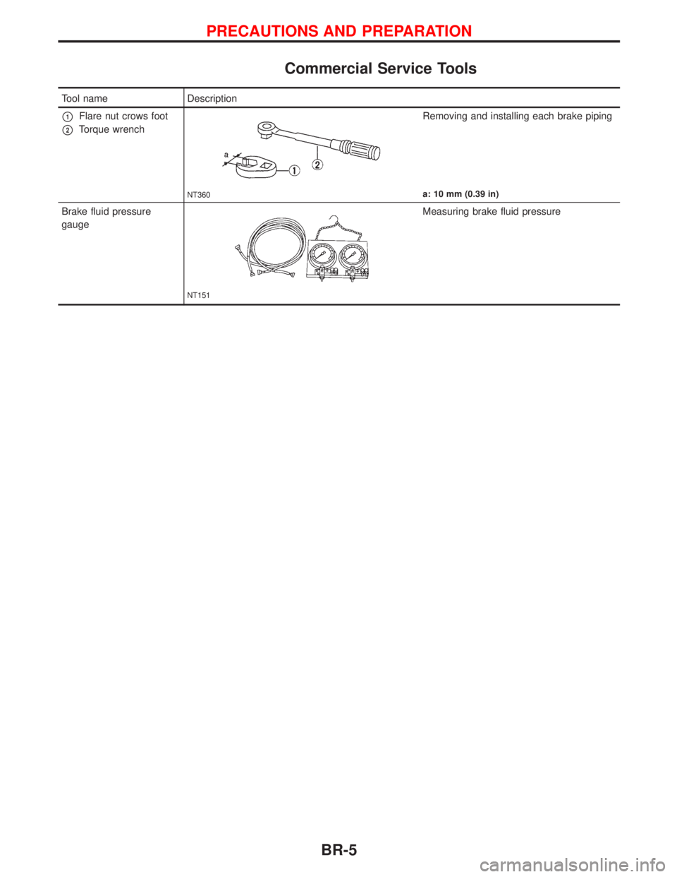
Commercial Service Tools
Tool name Description
p1Flare nut crows foot
p2Torque wrench
NT360
Removing and installing each brake piping
a: 10 mm (0.39 in)
Brake fluid pressure
gauge
NT151
Measuring brake fluid pressure
PRECAUTIONS AND PREPARATION
BR-5
Page 132 of 2267
Removal
CAUTION:
lBe careful not to splash brake fluid on painted areas; it
may cause paint damage. If brake fluid is splashed on
painted areas, wash it away with water immediately.
lAll hoses and tubes must be free from excessive
bending, twisting and pulling.
lFor rear disc caliper, care should be taken as not to let
air enter the body.
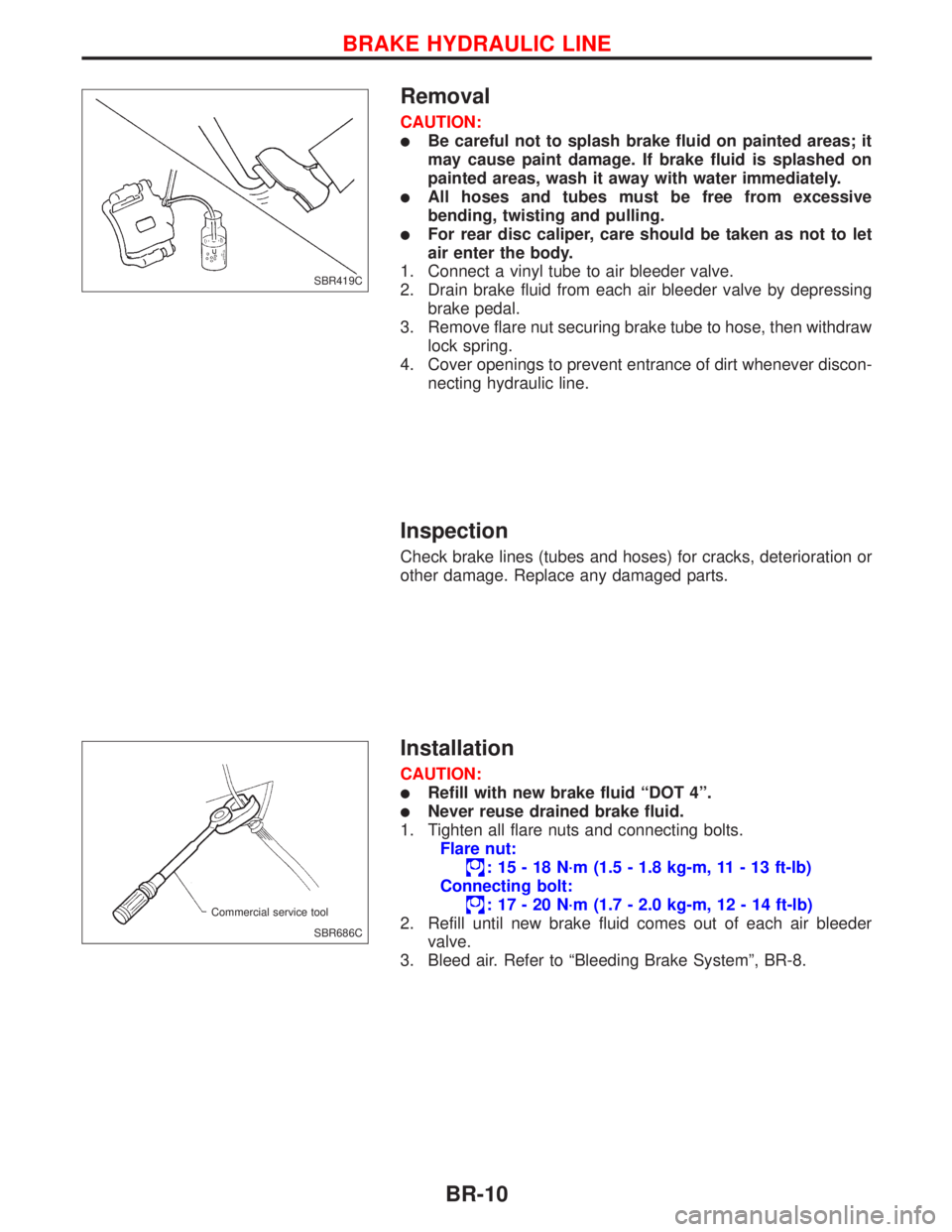
1. Connect a vinyl tube to air bleeder valve.
2. Drain brake fluid from each air bleeder valve by depressing
brake pedal.
3. Remove flare nut securing brake tube to hose, then withdraw
lock spring.
4. Cover openings to prevent entrance of dirt whenever discon-
necting hydraulic line.
Inspection
Check brake lines (tubes and hoses) for cracks, deterioration or
other damage. Replace any damaged parts.
Installation
CAUTION:
lRefill with new brake fluid ªDOT 4º.
lNever reuse drained brake fluid.
1. Tighten all flare nuts and connecting bolts.
Flare nut:
: 15 - 18 N´m (1.5 - 1.8 kg-m, 11 - 13 ft-lb)
Connecting bolt:
: 17 - 20 N´m (1.7 - 2.0 kg-m, 12 - 14 ft-lb)
2. Refill until new brake fluid comes out of each air bleeder
valve.
3. Bleed air. Refer to ªBleeding Brake Systemº, BR-8.
SBR419C
SBR686C Commercial service tool
BRAKE HYDRAULIC LINE
BR-10
Page 140 of 2267
On-vehicle Service
OPERATING CHECK
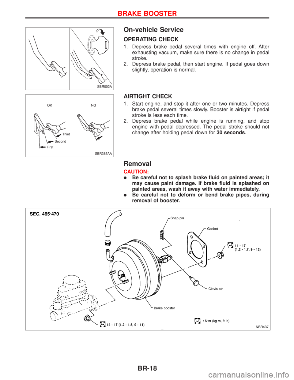
1. Depress brake pedal several times with engine off. After
exhausting vacuum, make sure there is no change in pedal
stroke.
2. Depress brake pedal, then start engine. If pedal goes down
slightly, operation is normal.
AIRTIGHT CHECK
1. Start engine, and stop it after one or two minutes. Depress
brake pedal several times slowly. Booster is airtight if pedal
stroke is less each time.
2. Depress brake pedal while engine is running, and stop
engine with pedal depressed. The pedal stroke should not
change after holding pedal down for30 seconds.
Removal
CAUTION:
lBe careful not to splash brake fluid on painted areas; it
may cause paint damage. If brake fluid is splashed on
painted areas, wash it away with water immediately.
lBe careful not to deform or bend brake pipes, during
removal of booster.
SBR002A
SBR365AA OK NG
Third
Second
First
NBR437
BRAKE BOOSTER
BR-18
Page 159 of 2267
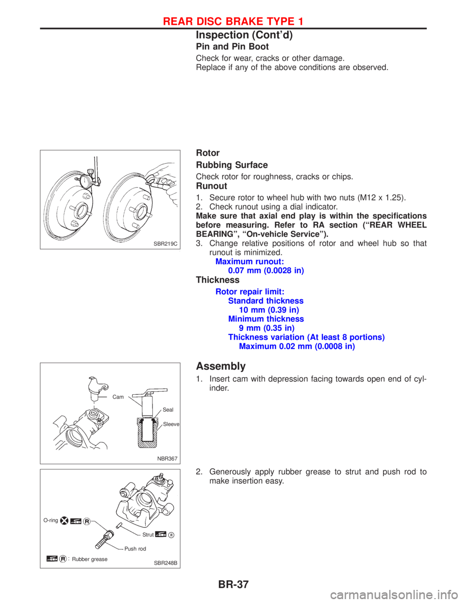
Pin and Pin Boot
Check for wear, cracks or other damage.
Replace if any of the above conditions are observed.
Rotor
Rubbing Surface
Check rotor for roughness, cracks or chips.
Runout
1. Secure rotor to wheel hub with two nuts (M12 x 1.25).
2. Check runout using a dial indicator.
Make sure that axial end play is within the specifications
before measuring. Refer to RA section (ªREAR WHEEL
BEARINGº, ªOn-vehicle Serviceº).
3. Change relative positions of rotor and wheel hub so that
runout is minimized.
Maximum runout:
0.07 mm (0.0028 in)
Thickness
Rotor repair limit:
Standard thickness
10 mm (0.39 in)
Minimum thickness
9 mm (0.35 in)
Thickness variation (At least 8 portions)
Maximum 0.02 mm (0.0008 in)
Assembly
1. Insert cam with depression facing towards open end of cyl-
inder.
2. Generously apply rubber grease to strut and push rod to
make insertion easy.
SBR219C
NBR367Sleeve Seal Cam
O-ring
Strut
pR
Push rod
Rubber grease
SBR248B
REAR DISC BRAKE TYPE 1
Inspection (Cont'd)
BR-37
Page 160 of 2267
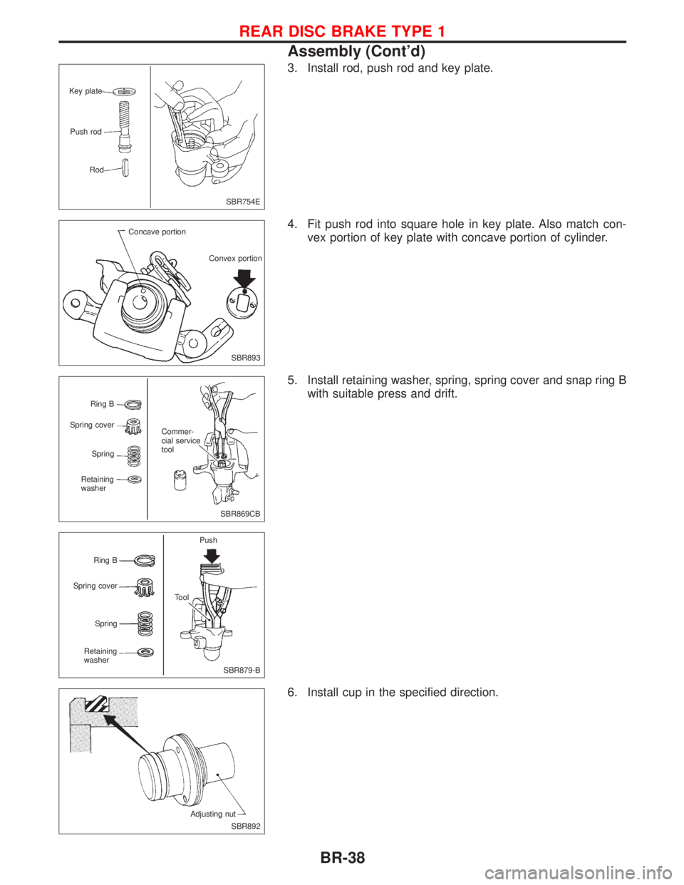
3. Install rod, push rod and key plate.
4. Fit push rod into square hole in key plate. Also match con-
vex portion of key plate with concave portion of cylinder.
5. Install retaining washer, spring, spring cover and snap ring B
with suitable press and drift.
6. Install cup in the specified direction.
SBR754E Key plate
Push rod
Rod
SBR893 Concave portion
Convex portion
SBR869CB Ring B
Spring cover
Spring
Retaining
washerCommer-
cial service
tool
SBR879-B Ring B
Spring cover
Spring
Retaining
washerPush
Tool
SBR892 Adjusting nut
REAR DISC BRAKE TYPE 1
Assembly (Cont'd)
BR-38
Page 162 of 2267
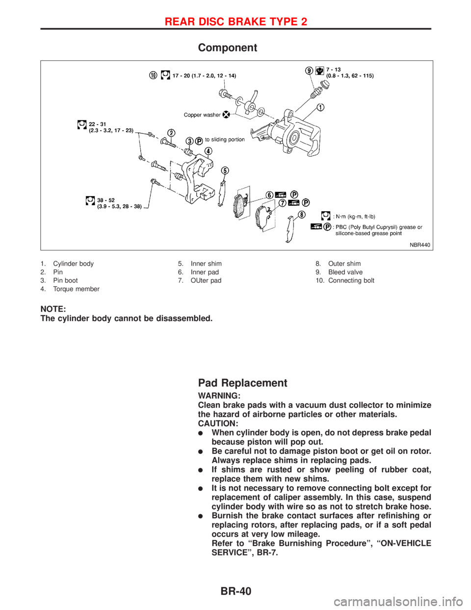
Component
1. Cylinder body
2. Pin
3. Pin boot
4. Torque member5. Inner shim
6. Inner pad
7. OUter pad8. Outer shim
9. Bleed valve
10. Connecting bolt
NOTE:
The cylinder body cannot be disassembled.
Pad Replacement
WARNING:
Clean brake pads with a vacuum dust collector to minimize
the hazard of airborne particles or other materials.
CAUTION:
lWhen cylinder body is open, do not depress brake pedal
because piston will pop out.
lBe careful not to damage piston boot or get oil on rotor.
Always replace shims in replacing pads.
lIf shims are rusted or show peeling of rubber coat,
replace them with new shims.
lIt is not necessary to remove connecting bolt except for
replacement of caliper assembly. In this case, suspend
cylinder body with wire so as not to stretch brake hose.
lBurnish the brake contact surfaces after refinishing or
replacing rotors, after replacing pads, or if a soft pedal
occurs at very low mileage.
Refer to ªBrake Burnishing Procedureº, ªON-VEHICLE
SERVICEº, BR-7.
NBR440
REAR DISC BRAKE TYPE 2
BR-40
Page 165 of 2267
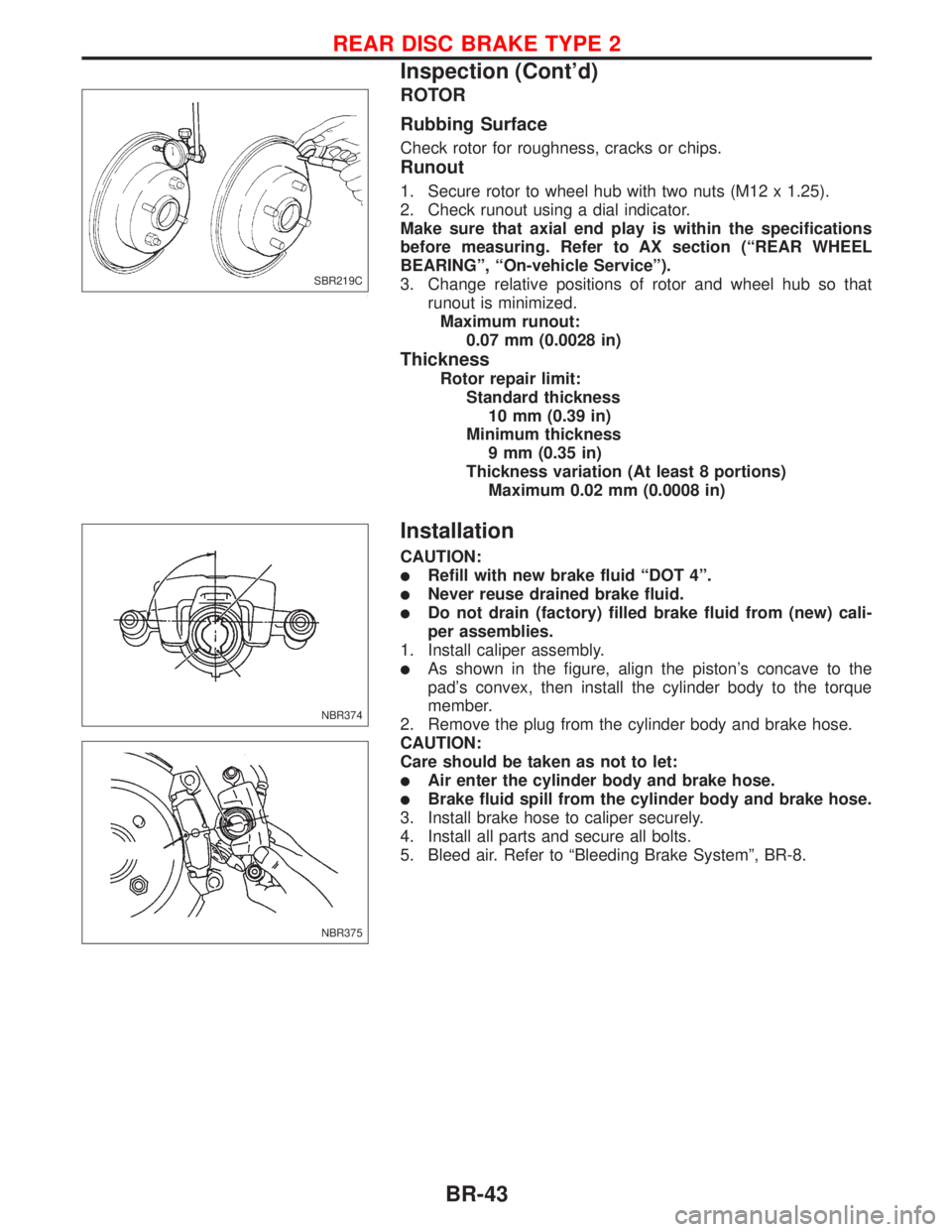
ROTOR
Rubbing Surface
Check rotor for roughness, cracks or chips.
Runout
1. Secure rotor to wheel hub with two nuts (M12 x 1.25).
2. Check runout using a dial indicator.
Make sure that axial end play is within the specifications
before measuring. Refer to AX section (ªREAR WHEEL
BEARINGº, ªOn-vehicle Serviceº).
3. Change relative positions of rotor and wheel hub so that
runout is minimized.
Maximum runout:
0.07 mm (0.0028 in)
Thickness
Rotor repair limit:
Standard thickness
10 mm (0.39 in)
Minimum thickness
9 mm (0.35 in)
Thickness variation (At least 8 portions)
Maximum 0.02 mm (0.0008 in)
Installation
CAUTION:
lRefill with new brake fluid ªDOT 4º.
lNever reuse drained brake fluid.
lDo not drain (factory) filled brake fluid from (new) cali-
per assemblies.
1. Install caliper assembly.
lAs shown in the figure, align the piston's concave to the
pad's convex, then install the cylinder body to the torque
member.
2. Remove the plug from the cylinder body and brake hose.
CAUTION:
Care should be taken as not to let:
lAir enter the cylinder body and brake hose.
lBrake fluid spill from the cylinder body and brake hose.
3. Install brake hose to caliper securely.
4. Install all parts and secure all bolts.
5. Bleed air. Refer to ªBleeding Brake Systemº, BR-8.
SBR219C
NBR374
NBR375
REAR DISC BRAKE TYPE 2
Inspection (Cont'd)
BR-43
Page 168 of 2267
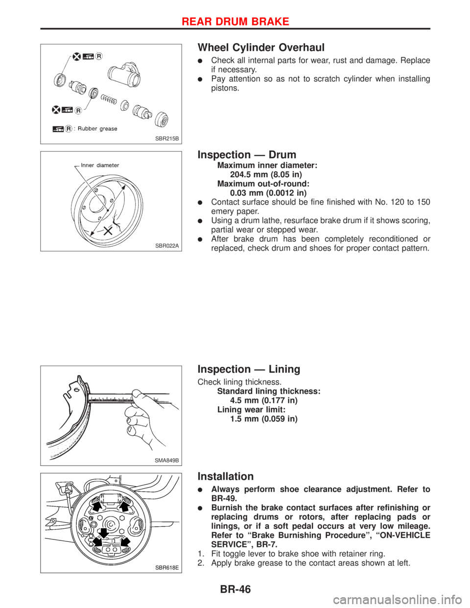
Wheel Cylinder Overhaul
lCheck all internal parts for wear, rust and damage. Replace
if necessary.
lPay attention so as not to scratch cylinder when installing
pistons.
Inspection Ð Drum
Maximum inner diameter:
204.5 mm (8.05 in)
Maximum out-of-round:
0.03 mm (0.0012 in)
lContact surface should be fine finished with No. 120 to 150
emery paper.
lUsing a drum lathe, resurface brake drum if it shows scoring,
partial wear or stepped wear.
lAfter brake drum has been completely reconditioned or
replaced, check drum and shoes for proper contact pattern.
Inspection Ð Lining
Check lining thickness.
Standard lining thickness:
4.5 mm (0.177 in)
Lining wear limit:
1.5 mm (0.059 in)
Installation
lAlways perform shoe clearance adjustment. Refer to
BR-49.
lBurnish the brake contact surfaces after refinishing or
replacing drums or rotors, after replacing pads or
linings, or if a soft pedal occurs at very low mileage.
Refer to ªBrake Burnishing Procedureº, ªON-VEHICLE
SERVICEº, BR-7.
1. Fit toggle lever to brake shoe with retainer ring.
2. Apply brake grease to the contact areas shown at left.
SBR215B
SBR022A
SMA849B
SBR618E
REAR DRUM BRAKE
BR-46