1999 NISSAN PRIMERA service
[x] Cancel search: servicePage 32 of 2267
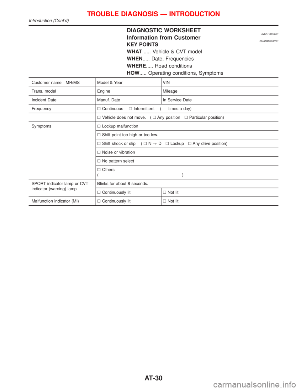
DIAGNOSTIC WORKSHEET=NCAT0023S01Information from CustomerNCAT0023S0101KEY POINTS
WHAT..... Vehicle & CVT model
WHEN..... Date, Frequencies
WHERE..... Road conditions
HOW..... Operating conditions, Symptoms
Customer name MR/MS Model & Year VIN
Trans. model Engine Mileage
Incident Date Manuf. Date In Service Date
FrequencylContinuouslIntermittent ( times a day)
lVehicle does not move. (lAny positionlParticular position)
SymptomslLockup malfunction
lShift point too high or too low.
lShift shock or slip (lN,DlLockuplAny drive position)
lNoise or vibration
lNo pattern select
lOthers
()
SPORT indicator lamp or CVT
indicator (warning) lampBlinks for about 8 seconds.
lContinuously litlNot lit
Malfunction indicator (MI)lContinuously litlNot lit
TROUBLE DIAGNOSIS Ð INTRODUCTION
Introduction (Cont'd)
AT-30
Page 35 of 2267
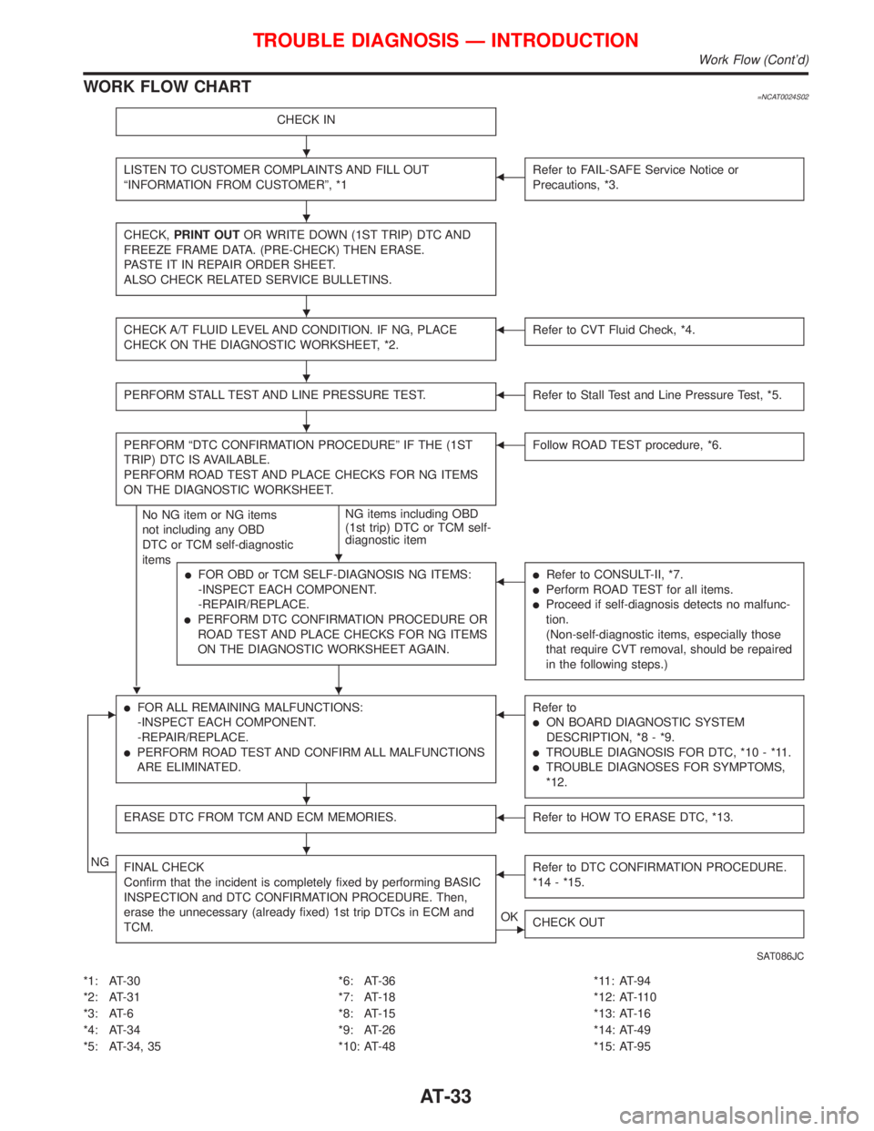
WORK FLOW CHART=NCAT0024S02
CHECK IN
LISTEN TO CUSTOMER COMPLAINTS AND FILL OUT
ªINFORMATION FROM CUSTOMERº, *1FRefer to FAIL-SAFE Service Notice or
Precautions, *3.
CHECK,PRINT OUTOR WRITE DOWN (1ST TRIP) DTC AND
FREEZE FRAME DATA. (PRE-CHECK) THEN ERASE.
PASTE IT IN REPAIR ORDER SHEET.
ALSO CHECK RELATED SERVICE BULLETINS.
CHECK A/T FLUID LEVEL AND CONDITION. IF NG, PLACE
CHECK ON THE DIAGNOSTIC WORKSHEET, *2.FRefer to CVT Fluid Check, *4.
PERFORM STALL TEST AND LINE PRESSURE TEST.FRefer to Stall Test and Line Pressure Test, *5.
PERFORM ªDTC CONFIRMATION PROCEDUREº IF THE (1ST
TRIP) DTC IS AVAILABLE.
PERFORM ROAD TEST AND PLACE CHECKS FOR NG ITEMS
ON THE DIAGNOSTIC WORKSHEET.
H
No NG item or NG items
not including any OBD
DTC or TCM self-diagnostic
itemsNG items including OBD
(1st trip) DTC or TCM self-
diagnostic item
FFollow ROAD TEST procedure, *6.
lFOR OBD or TCM SELF-DIAGNOSIS NG ITEMS:
-INSPECT EACH COMPONENT.
-REPAIR/REPLACE.
lPERFORM DTC CONFIRMATION PROCEDURE OR
ROAD TEST AND PLACE CHECKS FOR NG ITEMS
ON THE DIAGNOSTIC WORKSHEET AGAIN.
FlRefer to CONSULT-II, *7.
lPerform ROAD TEST for all items.
lProceed if self-diagnosis detects no malfunc-
tion.
(Non-self-diagnostic items, especially those
that require CVT removal, should be repaired
in the following steps.)
ElFOR ALL REMAINING MALFUNCTIONS:
-INSPECT EACH COMPONENT.
-REPAIR/REPLACE.
lPERFORM ROAD TEST AND CONFIRM ALL MALFUNCTIONS
ARE ELIMINATED.
FRefer to
lON BOARD DIAGNOSTIC SYSTEM
DESCRIPTION, *8 - *9.
lTROUBLE DIAGNOSIS FOR DTC, *10 - *11.
lTROUBLE DIAGNOSES FOR SYMPTOMS,
*12.
ERASE DTC FROM TCM AND ECM MEMORIES.FRefer to HOW TO ERASE DTC, *13.
NGFINAL CHECK
Confirm that the incident is completely fixed by performing BASIC
INSPECTION and DTC CONFIRMATION PROCEDURE. Then,
erase the unnecessary (already fixed) 1st trip DTCs in ECM and
TCM.FRefer to DTC CONFIRMATION PROCEDURE.
*14 - *15.
EOK
CHECK OUT
SAT086JC
*1: AT-30
*2: AT-31
*3: AT-6
*4: AT-34
*5: AT-34, 35*6: AT-36
*7: AT-18
*8: AT-15
*9: AT-26
*10: AT-48*11: AT-94
*12: AT-110
*13: AT-16
*14: AT-49
*15: AT-95
TROUBLE DIAGNOSIS Ð INTRODUCTION
Work Flow (Cont'd)
H
H
H
H
H
H
H
H
H
AT-33
Page 116 of 2267
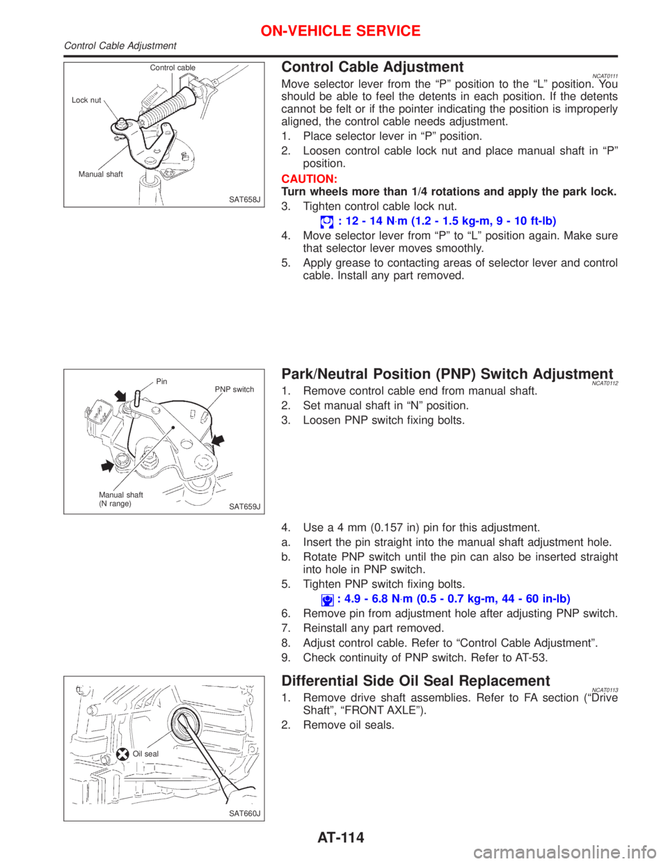
Control Cable AdjustmentNCAT0111Move selector lever from the ªPº position to the ªLº position. You
should be able to feel the detents in each position. If the detents
cannot be felt or if the pointer indicating the position is improperly
aligned, the control cable needs adjustment.
1. Place selector lever in ªPº position.
2. Loosen control cable lock nut and place manual shaft in ªPº
position.
CAUTION:
Turn wheels more than 1/4 rotations and apply the park lock.
3. Tighten control cable lock nut.
:12-14N×m (1.2 - 1.5 kg-m,9-10ft-lb)
4. Move selector lever from ªPº to ªLº position again. Make sure
that selector lever moves smoothly.
5. Apply grease to contacting areas of selector lever and control
cable. Install any part removed.
Park/Neutral Position (PNP) Switch AdjustmentNCAT01121. Remove control cable end from manual shaft.
2. Set manual shaft in ªNº position.
3. Loosen PNP switch fixing bolts.
4. Usea4mm(0.157 in) pin for this adjustment.
a. Insert the pin straight into the manual shaft adjustment hole.
b. Rotate PNP switch until the pin can also be inserted straight
into hole in PNP switch.
5. Tighten PNP switch fixing bolts.
: 4.9 - 6.8 N×m (0.5 - 0.7 kg-m, 44 - 60 in-lb)
6. Remove pin from adjustment hole after adjusting PNP switch.
7. Reinstall any part removed.
8. Adjust control cable. Refer to ªControl Cable Adjustmentº.
9. Check continuity of PNP switch. Refer to AT-53.
Differential Side Oil Seal ReplacementNCAT01131. Remove drive shaft assemblies. Refer to FA section (ªDrive
Shaftº, ªFRONT AXLEº).
2. Remove oil seals.
SAT658J Control cable
Lock nut
Manual shaft
SAT659J Pin
PNP switch
Manual shaft
(N range)
SAT660J Oil seal
ON-VEHICLE SERVICE
Control Cable Adjustment
AT-114
Page 117 of 2267
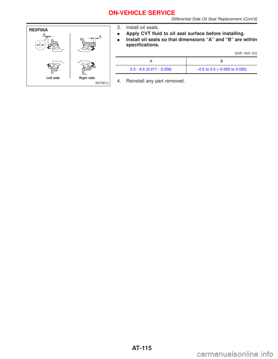
3. Install oil seals.
IApply CVT fluid to oil seal surface before installing.
IInstall oil seals so that dimensions ªAº and ªBº are within
specifications.
Unit: mm (in)
AB
5.5 - 6.5 (0.217 - 0.256) þ0.5 to 0.5 (þ0.020 to 0.020)
4. Reinstall any part removed.SAT661J Left side Right side
ON-VEHICLE SERVICE
Differential Side Oil Seal Replacement (Cont'd)
AT-115
Page 122 of 2267
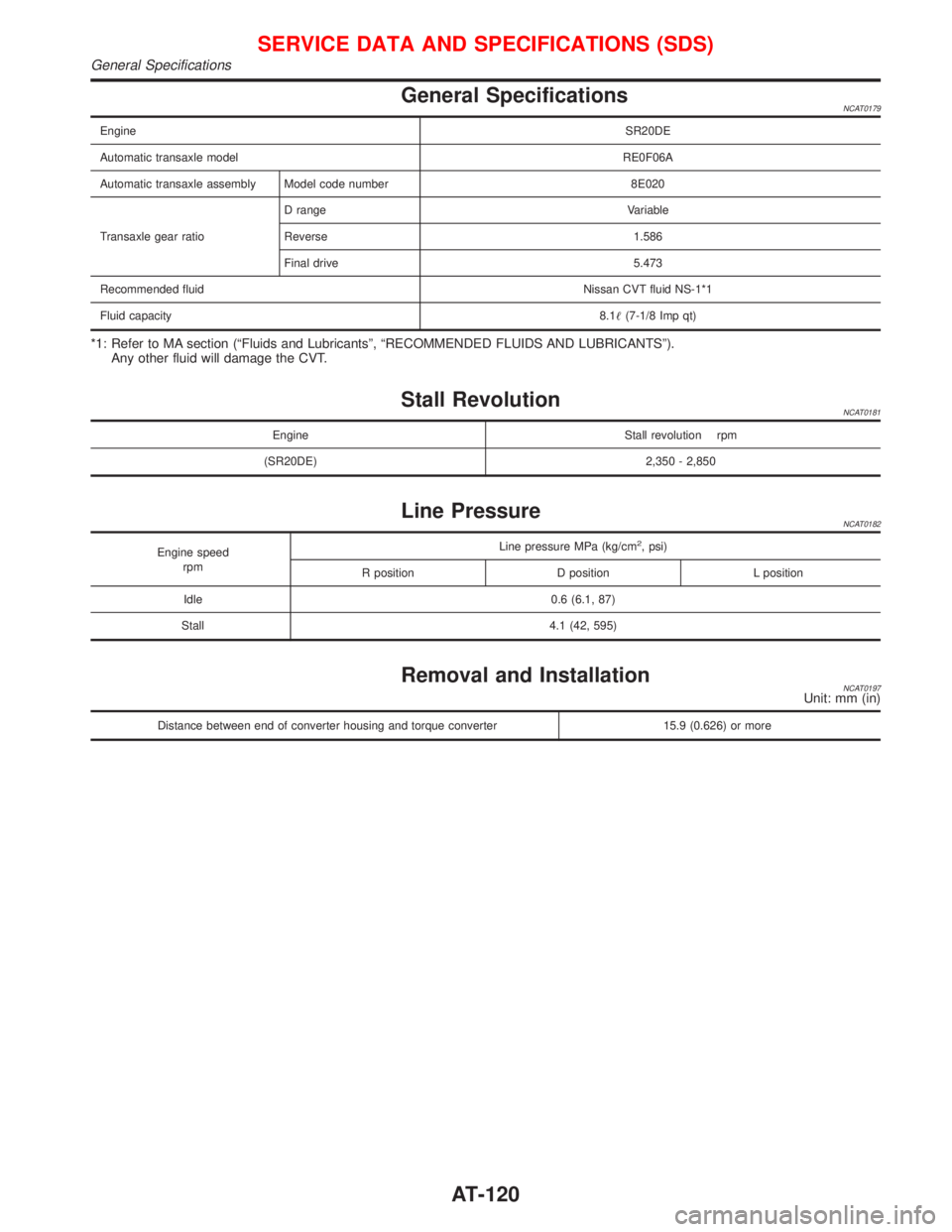
General SpecificationsNCAT0179
EngineSR20DE
Automatic transaxle modelRE0F06A
Automatic transaxle assembly Model code number 8E020
Transaxle gear ratioD range Variable
Reverse 1.586
Final drive 5.473
Recommended fluidNissan CVT fluid NS-1*1
Fluid capacity8.1(7-1/8 Imp qt)
*1: Refer to MA section (ªFluids and Lubricantsº, ªRECOMMENDED FLUIDS AND LUBRICANTSº).
Any other fluid will damage the CVT.
Stall RevolutionNCAT0181
Engine Stall revolution rpm
(SR20DE) 2,350 - 2,850
Line PressureNCAT0182
Engine speed
rpmLine pressure MPa (kg/cm2, psi)
R position D position L position
Idle 0.6 (6.1, 87)
Stall 4.1 (42, 595)
Removal and InstallationNCAT0197Unit: mm (in)
Distance between end of converter housing and torque converter 15.9 (0.626) or more
SERVICE DATA AND SPECIFICATIONS (SDS)
General Specifications
AT-120
Page 123 of 2267
BRAKE SYSTEM
SECTION
BR
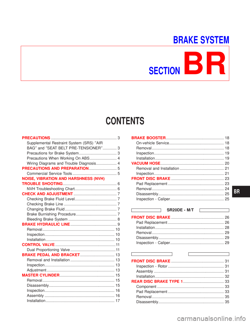
CONTENTS
PRECAUTIONS............................................................. 3
Supplemental Restraint System (SRS)²AIR
BAG²and²SEAT BELT PRE-TENSIONER²............. 3
Precautions for Brake System ................................... 3
Precautions When Working On ABS ......................... 4
Wiring Diagrams and Trouble Diagnosis ................... 4
PRECAUTIONS AND PREPARATION.......................... 5
Commercial Service Tools ......................................... 5
NOISE, VIBRATION AND HARSHNESS (NVH)
TROUBLE SHOOTING.................................................. 6
NVH Troubleshooting Chart....................................... 6
CHECK AND ADJUSTMENT........................................ 7
Checking Brake Fluid Level....................................... 7
Checking Brake Line ................................................. 7
Changing Brake Fluid ................................................ 7
Brake Burnishing Procedure...................................... 7
Bleeding Brake System ............................................. 8
BRAKE HYDRAULIC LINE........................................... 9
Removal ................................................................... 10
Inspection................................................................. 10
Installation ................................................................ 10
CONTROL VALVE........................................................ 11
Dual Proportioning Valve .......................................... 11
BRAKE PEDAL AND BRACKET................................ 13
Removal and Installation ......................................... 13
Inspection................................................................. 13
Adjustment ............................................................... 13
MASTER CYLINDER................................................... 15
Removal ................................................................... 15
Disassembly............................................................. 15
Inspection................................................................. 16
Assembly ................................................................. 16
Installation ................................................................ 17BRAKE BOOSTER...................................................... 18
On-vehicle Service................................................... 18
Removal ................................................................... 18
Inspection................................................................. 19
Installation ................................................................ 19
VACUUM HOSE........................................................... 20
Removal and Installation ......................................... 21
Inspection................................................................. 21
FRONT DISC BRAKE................................................. 23
Pad Replacement .................................................... 23
Removal ................................................................... 24
Disassembly............................................................. 25
Inspection - Caliper.................................................. 25
SR20DE - M/T
FRONT DISC BRAKE................................................. 26
Pad Replacement .................................................... 26
Installation ................................................................ 28
Removal ................................................................... 29
Disassembly............................................................. 29
Inspection - Caliper.................................................. 29
FRONT DISC BRAKE................................................. 31
Inspection - Rotor .................................................... 31
Assembly ................................................................. 31
Installation ................................................................ 32
REAR DISC BRAKE TYPE 1...................................... 33
Component .............................................................. 33
Pad Replacement .................................................... 33
Removal ................................................................... 35
Disassembly............................................................. 35
BR
Page 124 of 2267
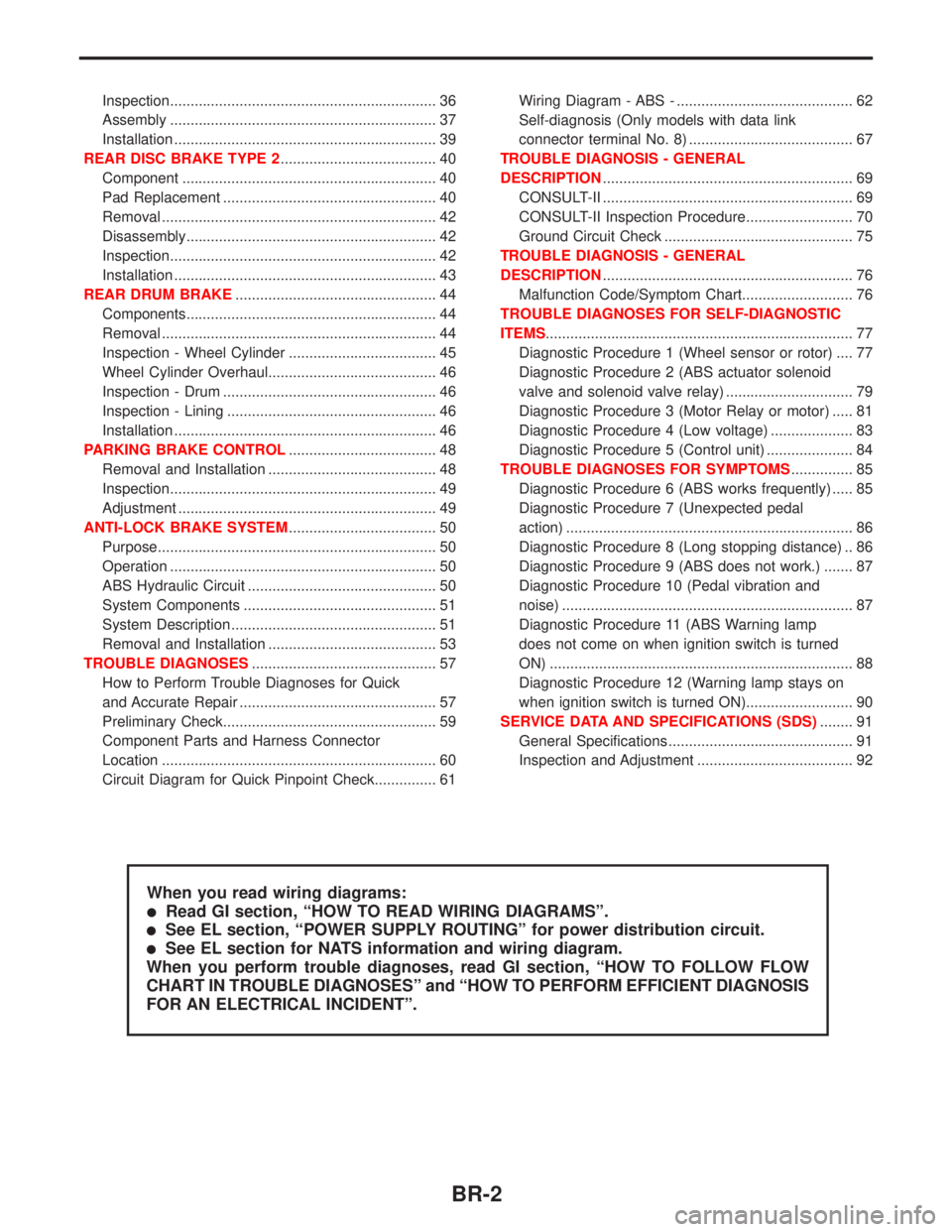
Inspection................................................................. 36
Assembly ................................................................. 37
Installation ................................................................ 39
REAR DISC BRAKE TYPE 2...................................... 40
Component .............................................................. 40
Pad Replacement .................................................... 40
Removal ................................................................... 42
Disassembly............................................................. 42
Inspection................................................................. 42
Installation ................................................................ 43
REAR DRUM BRAKE................................................. 44
Components............................................................. 44
Removal ................................................................... 44
Inspection - Wheel Cylinder .................................... 45
Wheel Cylinder Overhaul......................................... 46
Inspection - Drum .................................................... 46
Inspection - Lining ................................................... 46
Installation ................................................................ 46
PARKING BRAKE CONTROL.................................... 48
Removal and Installation ......................................... 48
Inspection................................................................. 49
Adjustment ............................................................... 49
ANTI-LOCK BRAKE SYSTEM.................................... 50
Purpose.................................................................... 50
Operation ................................................................. 50
ABS Hydraulic Circuit .............................................. 50
System Components ............................................... 51
System Description .................................................. 51
Removal and Installation ......................................... 53
TROUBLE DIAGNOSES............................................. 57
How to Perform Trouble Diagnoses for Quick
and Accurate Repair ................................................ 57
Preliminary Check.................................................... 59
Component Parts and Harness Connector
Location ................................................................... 60
Circuit Diagram for Quick Pinpoint Check............... 61Wiring Diagram - ABS - ........................................... 62
Self-diagnosis (Only models with data link
connector terminal No. 8) ........................................ 67
TROUBLE DIAGNOSIS - GENERAL
DESCRIPTION............................................................. 69
CONSULT-II ............................................................. 69
CONSULT-II Inspection Procedure.......................... 70
Ground Circuit Check .............................................. 75
TROUBLE DIAGNOSIS - GENERAL
DESCRIPTION............................................................. 76
Malfunction Code/Symptom Chart........................... 76
TROUBLE DIAGNOSES FOR SELF-DIAGNOSTIC
ITEMS........................................................................... 77
Diagnostic Procedure 1 (Wheel sensor or rotor) .... 77
Diagnostic Procedure 2 (ABS actuator solenoid
valve and solenoid valve relay) ............................... 79
Diagnostic Procedure 3 (Motor Relay or motor) ..... 81
Diagnostic Procedure 4 (Low voltage) .................... 83
Diagnostic Procedure 5 (Control unit) ..................... 84
TROUBLE DIAGNOSES FOR SYMPTOMS............... 85
Diagnostic Procedure 6 (ABS works frequently) ..... 85
Diagnostic Procedure 7 (Unexpected pedal
action) ...................................................................... 86
Diagnostic Procedure 8 (Long stopping distance) .. 86
Diagnostic Procedure 9 (ABS does not work.) ....... 87
Diagnostic Procedure 10 (Pedal vibration and
noise) ....................................................................... 87
Diagnostic Procedure 11 (ABS Warning lamp
does not come on when ignition switch is turned
ON) .......................................................................... 88
Diagnostic Procedure 12 (Warning lamp stays on
when ignition switch is turned ON).......................... 90
SERVICE DATA AND SPECIFICATIONS (SDS)........ 91
General Specifications ............................................. 91
Inspection and Adjustment ...................................... 92
When you read wiring diagrams:
lRead GI section, ªHOW TO READ WIRING DIAGRAMSº.
lSee EL section, ªPOWER SUPPLY ROUTINGº for power distribution circuit.
lSee EL section for NATS information and wiring diagram.
When you perform trouble diagnoses, read GI section, ªHOW TO FOLLOW FLOW
CHART IN TROUBLE DIAGNOSESº and ªHOW TO PERFORM EFFICIENT DIAGNOSIS
FOR AN ELECTRICAL INCIDENTº.
BR-2
Page 125 of 2267
Supplemental Restraint System (SRS) ªAIR
BAGº and ªSEAT BELT PRE-TENSIONERº
The Supplemental Restraint System such as ªAIR BAGº and ªSEAT BELT PRE-TENSIONERº used along
with a seat belt, helps to reduce the risk or severity of injury to the driver and front passenger for certain
types of collision. The SRS system composition which is available to NISSAN MODEL P11 is as follows (The
composition varies according to the destination and optional equipment.):
lFor a frontal collision
The Supplemental Restraint System consists of driver air bag module (located in the center of the
steering wheel), front passenger air bag module (located on the instrument panel on passenger side),
front seat belt pre-tensioners, a diagnosis sensor unit, warning lamp, wiring harness and spiral cable.
lFor a side collision
The Supplemental Restraint System consists of front side air bag module (located in the outer side of
front seat), side air bag (satellite) sensor, diagnosis sensor unit (one of components of air bags for a
frontal collision), wiring harness, warning lamp (one of components of air bags for a frontal collision).
Information necessary to service the system safely is included in theRS sectionof this Service Manual.
WARNING:
lTo avoid rendering the SRS inoperative, which could increase the risk of personal injury or death
in the event of a collision which would result in air bag inflation, all maintenance should be per-
formed by an authorized NISSAN dealer.
lImproper maintenance, including incorrect removal and installation of the SRS, can lead to per-
sonal injury caused by unintentional activation of the system. For removal of Spiral Cable and
Air Bag Module, see the RS section.
lDo not use electrical test equipment on any circuit related to the SRS unless instructed to in this
Service Manual. Spiral cable and wiring harnesses covered with yellow insulation tape either just
before the harness connectors or for the complete harness are related to the SRS.
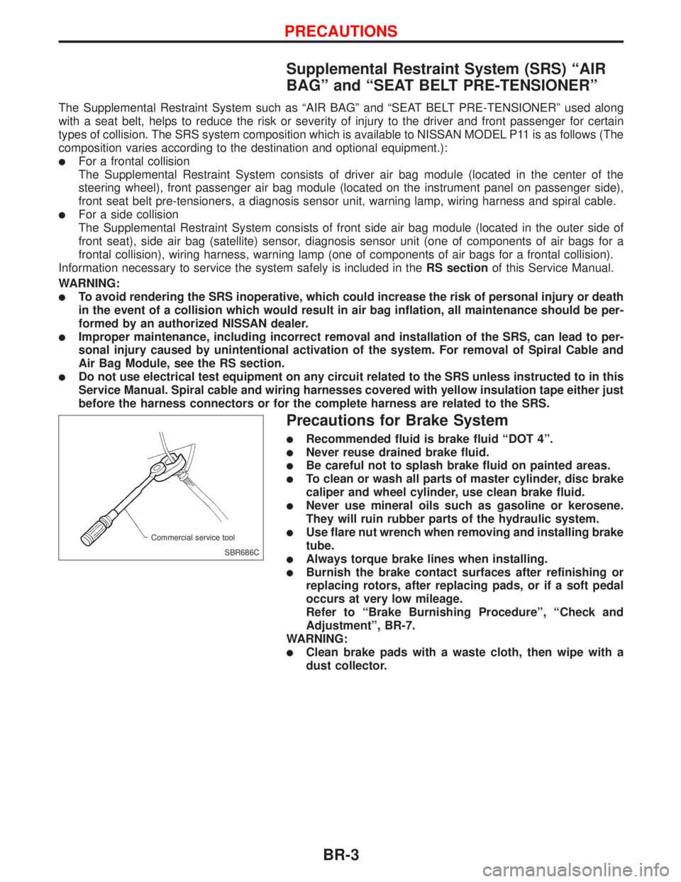
Precautions for Brake System
lRecommended fluid is brake fluid ªDOT 4º.
lNever reuse drained brake fluid.
lBe careful not to splash brake fluid on painted areas.
lTo clean or wash all parts of master cylinder, disc brake
caliper and wheel cylinder, use clean brake fluid.
lNever use mineral oils such as gasoline or kerosene.
They will ruin rubber parts of the hydraulic system.
lUse flare nut wrench when removing and installing brake
tube.
lAlways torque brake lines when installing.
lBurnish the brake contact surfaces after refinishing or
replacing rotors, after replacing pads, or if a soft pedal
occurs at very low mileage.
Refer to ªBrake Burnishing Procedureº, ªCheck and
Adjustmentº, BR-7.
WARNING:
lClean brake pads with a waste cloth, then wipe with a
dust collector.
SBR686C Commercial service tool
PRECAUTIONS
BR-3