1999 NISSAN PRIMERA fuel pressure
[x] Cancel search: fuel pressurePage 376 of 2267
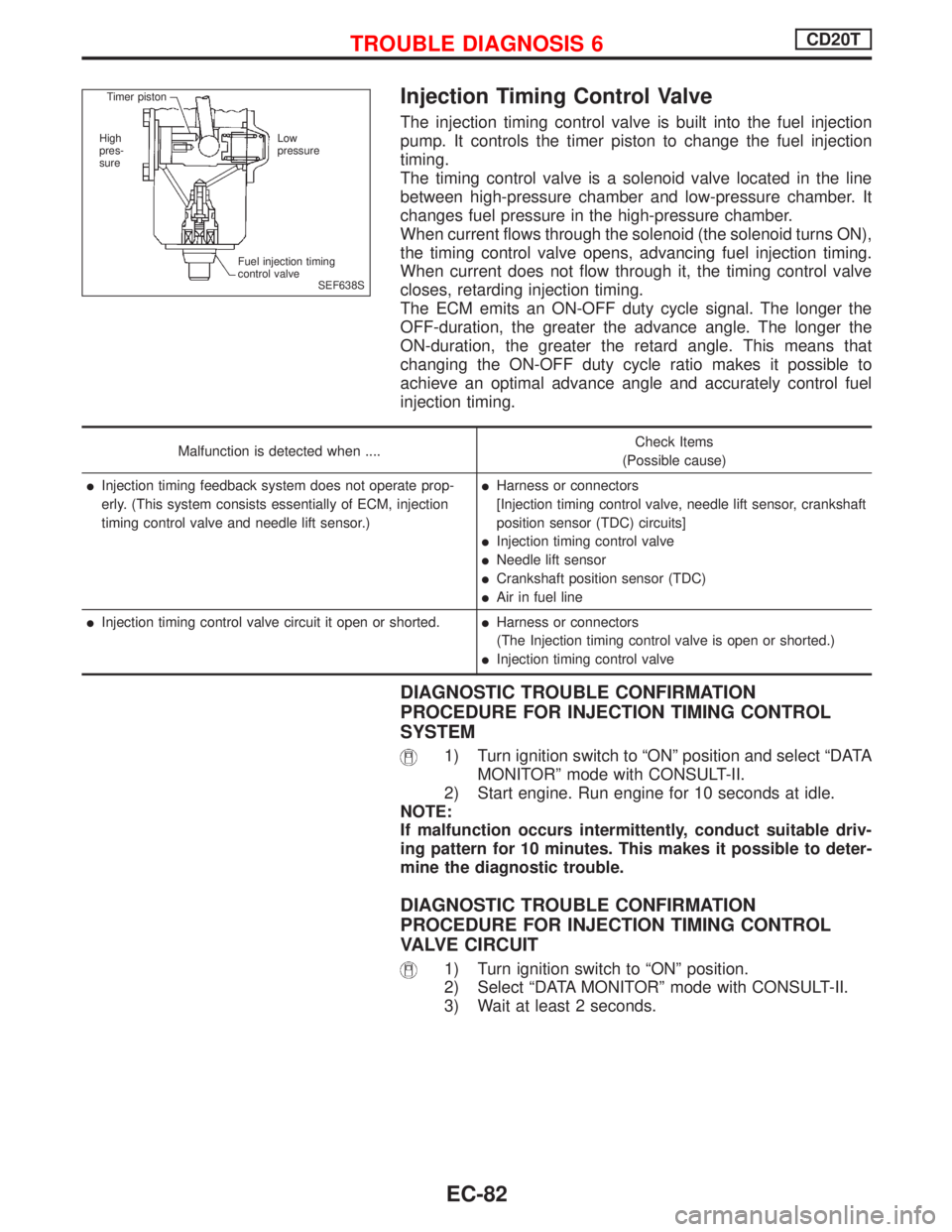
Injection Timing Control Valve
The injection timing control valve is built into the fuel injection
pump. It controls the timer piston to change the fuel injection
timing.
The timing control valve is a solenoid valve located in the line
between high-pressure chamber and low-pressure chamber. It
changes fuel pressure in the high-pressure chamber.
When current flows through the solenoid (the solenoid turns ON),
the timing control valve opens, advancing fuel injection timing.
When current does not flow through it, the timing control valve
closes, retarding injection timing.
The ECM emits an ON-OFF duty cycle signal. The longer the
OFF-duration, the greater the advance angle. The longer the
ON-duration, the greater the retard angle. This means that
changing the ON-OFF duty cycle ratio makes it possible to
achieve an optimal advance angle and accurately control fuel
injection timing.
Malfunction is detected when ....Check Items
(Possible cause)
lInjection timing feedback system does not operate prop-
erly. (This system consists essentially of ECM, injection
timing control valve and needle lift sensor.)lHarness or connectors
[Injection timing control valve, needle lift sensor, crankshaft
position sensor (TDC) circuits]
lInjection timing control valve
lNeedle lift sensor
lCrankshaft position sensor (TDC)
lAir in fuel line
lInjection timing control valve circuit it open or shorted.lHarness or connectors
(The Injection timing control valve is open or shorted.)
lInjection timing control valve
DIAGNOSTIC TROUBLE CONFIRMATION
PROCEDURE FOR INJECTION TIMING CONTROL
SYSTEM
1) Turn ignition switch to ªONº position and select ªDATA
MONITORº mode with CONSULT-II.
2) Start engine. Run engine for 10 seconds at idle.
NOTE:
If malfunction occurs intermittently, conduct suitable driv-
ing pattern for 10 minutes. This makes it possible to deter-
mine the diagnostic trouble.
DIAGNOSTIC TROUBLE CONFIRMATION
PROCEDURE FOR INJECTION TIMING CONTROL
VALVE CIRCUIT
1) Turn ignition switch to ªONº position.
2) Select ªDATA MONITORº mode with CONSULT-II.
3) Wait at least 2 seconds.
SEF638S Timer piston
High
pres-
sureLow
pressure
Fuel injection timing
control valve
TROUBLE DIAGNOSIS 6CD20T
EC-82
Page 441 of 2267
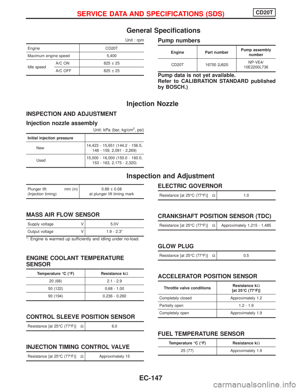
General Specifications
Unit : rpm
Engine CD20T
Maximum engine speed 5,400
Idle speedA/C ON 825 25
A/C OFF 825 25
Pump numbers
Engine Part numberPump assembly
number
CD20T 16700 2J620NP-VE4/
10E2200L736
Pump data is not yet available.
Refer to CALIBRATION STANDARD published
by BOSCH.)
Injection Nozzle
INSPECTION AND ADJUSTMENT
Injection nozzle assembly
Unit: kPa (bar, kg/cm2, psi)
Initial injection pressure
New14,423 - 15,651 (144.2 - 156.5,
148 - 159, 2,091 - 2,269)
Used15,000 - 16,000 (150.0 - 160.0,
153 - 163, 2,175 - 2,320)
Inspection and Adjustment
Plunger lift mm (in)
(Injection timing)0.89 0.08
at plunger lift timing mark
MASS AIR FLOW SENSOR
Supply voltage V 5.0V
Output voltage V 1.9 - 2.3*
*: Engine is warmed up sufficiently and idling under no-load.
ENGINE COOLANT TEMPERATURE
SENSOR
Temperature ÉC (ÉF) Resistance kW
20 (68) 2.1 - 2.9
50 (122) 0.68 - 1.00
90 (194) 0.236 - 0.260
CONTROL SLEEVE POSITION SENSOR
Resistance [at 25ÉC (77ÉF)]W6.0
INJECTION TIMING CONTROL VALVE
Resistance [at 25ÉC (77ÉF)]WApproximately 15
ELECTRIC GOVERNOR
Resistance [at 25ÉC (77ÉF)]W1.0
CRANKSHAFT POSITION SENSOR (TDC)
Resistance [at 25ÉC (77ÉF)]WApproximately 1,215 - 1,485
GLOW PLUG
Resistance [at 25ÉC (77ÉF)]W0.5
ACCELERATOR POSITION SENSOR
Throttle valve conditionsResistance kW
[at 25ÉC (77ÉF)]
Completely closed Approximately 1.2
Partially open 1.2 - 1.9
Completely open Approximately 1.9
FUEL TEMPERATURE SENSOR
Temperature ÉC (ÉF) Resistance kW
25 (77) Approximately 1.9
SERVICE DATA AND SPECIFICATIONS (SDS)CD20T
EC-147
Page 443 of 2267
ENGINE CONTROL SYSTEM
SECTION
EC
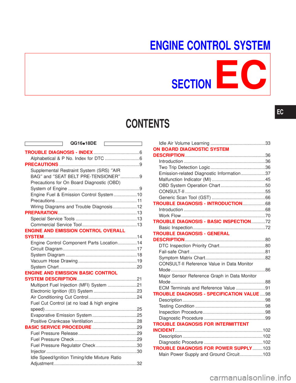
CONTENTS
QG16I18DE
TROUBLE DIAGNOSIS - INDEX....................................6
Alphabetical & P No. Index for DTC ...........................6
PRECAUTIONS...............................................................9
Supplemental Restraint System (SRS)²AIR
BAG²and²SEAT BELT PRE-TENSIONER²...............9
Precautions for On Board Diagnostic (OBD)
System of Engine ........................................................9
Engine Fuel & Emission Control System ..................10
Precautions ................................................................ 11
Wiring Diagrams and Trouble Diagnosis ...................12
PREPARATION..............................................................13
Special Service Tools ................................................13
Commercial Service Tool ...........................................13
ENGINE AND EMISSION CONTROL OVERALL
SYSTEM.........................................................................14
Engine Control Component Parts Location ...............14
Circuit Diagram ..........................................................17
System Diagram ........................................................18
Vacuum Hose Drawing ..............................................19
System Chart .............................................................20
ENGINE AND EMISSION BASIC CONTROL
SYSTEM DESCRIPTION...............................................21
Multiport Fuel Injection (MFI) System .......................21
Electronic Ignition (EI) System ..................................23
Air Conditioning Cut Control ......................................24
Fuel Cut Control (at no load & high engine
speed) ........................................................................25
Evaporative Emission System ...................................25
Positive Crankcase Ventilation ..................................28
BASIC SERVICE PROCEDURE...................................29
Fuel Pressure Release ..............................................29
Fuel Pressure Check .................................................29
Fuel Pressure Regulator Check ................................30
Injector .......................................................................30
Idle Speed/Ignition Timing/Idle Mixture Ratio
Adjustment .................................................................32Idle Air Volume Learning ...........................................33
ON BOARD DIAGNOSTIC SYSTEM
DESCRIPTION...............................................................36
Introduction ................................................................36
Two Trip Detection Logic ...........................................36
Emission-related Diagnostic Information ...................37
Malfunction Indicator (MI) ..........................................45
OBD System Operation Chart ...................................50
CONSULT-II ...............................................................55
Generic Scan Tool (GST) ..........................................66
TROUBLE DIAGNOSIS - INTRODUCTION..................68
Introduction ................................................................68
Work Flow ..................................................................70
TROUBLE DIAGNOSIS - BASIC INSPECTION...........72
Basic Inspection.........................................................72
TROUBLE DIAGNOSIS - GENERAL
DESCRIPTION...............................................................80
DTC Inspection Priority Chart....................................80
Fail-safe Chart ...........................................................81
Symptom Matrix Chart ...............................................82
CONSULT-II Reference Value in Data Monitor
Mode ..........................................................................86
Major Sensor Reference Graph in Data Monitor
Mode ..........................................................................88
ECM Terminals and Reference Value .......................91
TROUBLE DIAGNOSIS - SPECIFICATION VALUE....98
Description .................................................................98
Testing Condition .......................................................98
Inspection Procedure .................................................98
Diagnostic Procedure ................................................99
TROUBLE DIAGNOSIS FOR INTERMITTENT
INCIDENT.....................................................................102
Description ...............................................................102
Diagnostic Procedure ..............................................102
TROUBLE DIAGNOSIS FOR POWER SUPPLY........103
Main Power Supply and Ground Circuit ..................103
EC
Page 447 of 2267
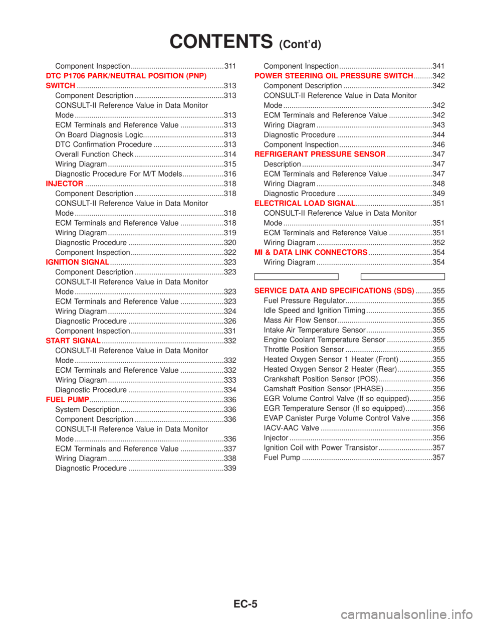
Component Inspection ............................................. 311
DTC P1706 PARK/NEUTRAL POSITION (PNP)
SWITCH.......................................................................313
Component Description ...........................................313
CONSULT-II Reference Value in Data Monitor
Mode ........................................................................313
ECM Terminals and Reference Value .....................313
On Board Diagnosis Logic.......................................313
DTC Confirmation Procedure ..................................313
Overall Function Check ...........................................314
Wiring Diagram ........................................................315
Diagnostic Procedure For M/T Models....................316
INJECTOR...................................................................318
Component Description ...........................................318
CONSULT-II Reference Value in Data Monitor
Mode ........................................................................318
ECM Terminals and Reference Value .....................318
Wiring Diagram ........................................................319
Diagnostic Procedure ..............................................320
Component Inspection .............................................322
IGNITION SIGNAL.......................................................323
Component Description ...........................................323
CONSULT-II Reference Value in Data Monitor
Mode ........................................................................323
ECM Terminals and Reference Value .....................323
Wiring Diagram ........................................................324
Diagnostic Procedure ..............................................326
Component Inspection .............................................331
START SIGNAL...........................................................332
CONSULT-II Reference Value in Data Monitor
Mode ........................................................................332
ECM Terminals and Reference Value .....................332
Wiring Diagram ........................................................333
Diagnostic Procedure ..............................................334
FUEL PUMP.................................................................336
System Description ..................................................336
Component Description ...........................................336
CONSULT-II Reference Value in Data Monitor
Mode ........................................................................336
ECM Terminals and Reference Value .....................337
Wiring Diagram ........................................................338
Diagnostic Procedure ..............................................339Component Inspection .............................................341
POWER STEERING OIL PRESSURE SWITCH.........342
Component Description ...........................................342
CONSULT-II Reference Value in Data Monitor
Mode ........................................................................342
ECM Terminals and Reference Value .....................342
Wiring Diagram ........................................................343
Diagnostic Procedure ..............................................344
Component Inspection .............................................346
REFRIGERANT PRESSURE SENSOR......................347
Description ...............................................................347
ECM Terminals and Reference Value .....................347
Wiring Diagram ........................................................348
Diagnostic Procedure ..............................................349
ELECTRICAL LOAD SIGNAL.....................................351
CONSULT-II Reference Value in Data Monitor
Mode ........................................................................351
ECM Terminals and Reference Value .....................351
Wiring Diagram ........................................................352
MI & DATA LINK CONNECTORS...............................354
Wiring Diagram ........................................................354
SERVICE DATA AND SPECIFICATIONS (SDS)........355
Fuel Pressure Regulator..........................................355
Idle Speed and Ignition Timing ................................355
Mass Air Flow Sensor..............................................355
Intake Air Temperature Sensor ................................355
Engine Coolant Temperature Sensor ......................355
Throttle Position Sensor ..........................................355
Heated Oxygen Sensor 1 Heater (Front) ................355
Heated Oxygen Sensor 2 Heater (Rear).................355
Crankshaft Position Sensor (POS) ..........................356
Camshaft Position Sensor (PHASE) .......................356
EGR Volume Control Valve (If so equipped)...........356
EGR Temperature Sensor (If so equipped).............356
EVAP Canister Purge Volume Control Valve ..........356
IACV-AAC Valve ......................................................356
Injector .....................................................................356
Ignition Coil with Power Transistor ..........................357
Fuel Pump ...............................................................357
CONTENTS(Cont'd)
EC-5
Page 455 of 2267
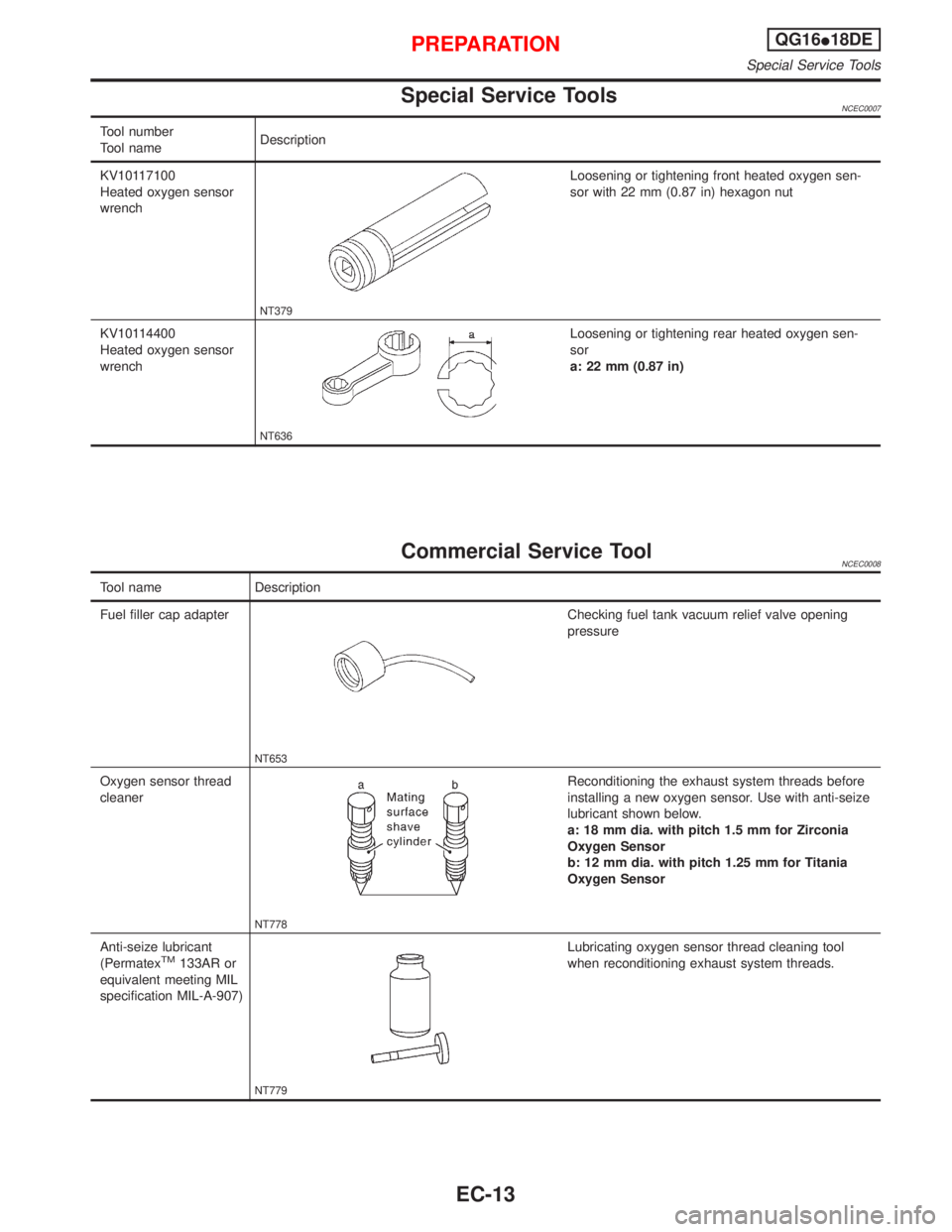
Special Service ToolsNCEC0007
Tool number
Tool nameDescription
KV10117100
Heated oxygen sensor
wrench
NT379
Loosening or tightening front heated oxygen sen-
sor with 22 mm (0.87 in) hexagon nut
KV10114400
Heated oxygen sensor
wrench
NT636
Loosening or tightening rear heated oxygen sen-
sor
a: 22 mm (0.87 in)
Commercial Service ToolNCEC0008
Tool name Description
Fuel filler cap adapter
NT653
Checking fuel tank vacuum relief valve opening
pressure
Oxygen sensor thread
cleaner
NT778
Reconditioning the exhaust system threads before
installing a new oxygen sensor. Use with anti-seize
lubricant shown below.
a: 18 mm dia. with pitch 1.5 mm for Zirconia
Oxygen Sensor
b: 12 mm dia. with pitch 1.25 mm for Titania
Oxygen Sensor
Anti-seize lubricant
(Permatex
TM133AR or
equivalent meeting MIL
specification MIL-A-907)
NT779
Lubricating oxygen sensor thread cleaning tool
when reconditioning exhaust system threads.
PREPARATIONQG16I18DE
Special Service Tools
EC-13
Page 461 of 2267
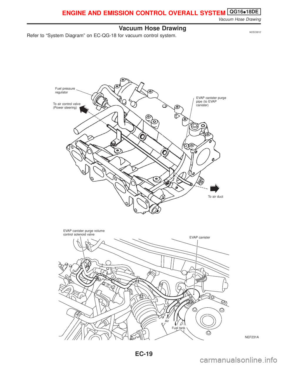
Vacuum Hose DrawingNCEC0012Refer to ªSystem Diagramº on EC-QG-18 for vacuum control system.
NEF231A Fuel pressure
regulator
EVAP canister purge
pipe (to EVAP
canister)
To air duct To air control valve
(Power steering)
EVAP canister purge volume
control solenoid valve
EVAP canister
Air
Fuel tank
ENGINE AND EMISSION CONTROL OVERALL SYSTEMQG16I18DE
Vacuum Hose Drawing
EC-19
Page 462 of 2267
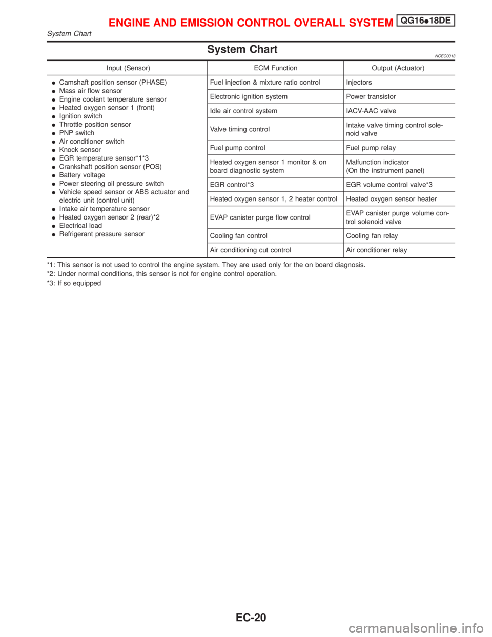
System ChartNCEC0013
Input (Sensor) ECM Function Output (Actuator)
ICamshaft position sensor (PHASE)
IMass air flow sensor
IEngine coolant temperature sensor
IHeated oxygen sensor 1 (front)
IIgnition switch
IThrottle position sensor
IPNP switch
IAir conditioner switch
IKnock sensor
IEGR temperature sensor*1*3
ICrankshaft position sensor (POS)
IBattery voltage
IPower steering oil pressure switch
IVehicle speed sensor or ABS actuator and
electric unit (control unit)
IIntake air temperature sensor
IHeated oxygen sensor 2 (rear)*2
IElectrical load
IRefrigerant pressure sensorFuel injection & mixture ratio control Injectors
Electronic ignition system Power transistor
Idle air control system IACV-AAC valve
Valve timing controlIntake valve timing control sole-
noid valve
Fuel pump control Fuel pump relay
Heated oxygen sensor 1 monitor & on
board diagnostic systemMalfunction indicator
(On the instrument panel)
EGR control*3 EGR volume control valve*3
Heated oxygen sensor 1, 2 heater control Heated oxygen sensor heater
EVAP canister purge flow controlEVAP canister purge volume con-
trol solenoid valve
Cooling fan control Cooling fan relay
Air conditioning cut control Air conditioner relay
*1: This sensor is not used to control the engine system. They are used only for the on board diagnosis.
*2: Under normal conditions, this sensor is not for engine control operation.
*3: If so equipped
ENGINE AND EMISSION CONTROL OVERALL SYSTEMQG16I18DE
System Chart
EC-20
Page 463 of 2267
Multiport Fuel Injection (MFI) System
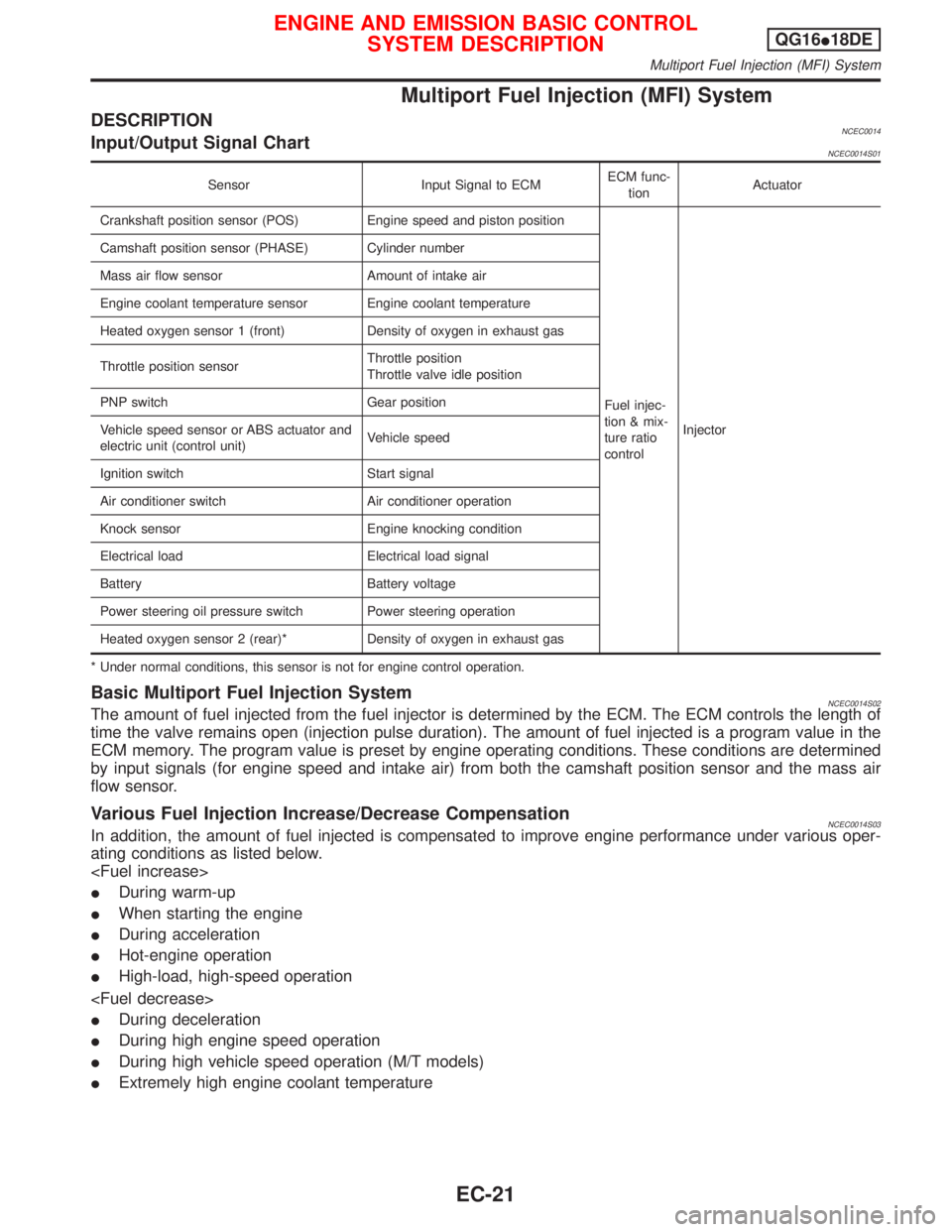
DESCRIPTIONNCEC0014Input/Output Signal ChartNCEC0014S01
Sensor Input Signal to ECMECM func-
tionActuator
Crankshaft position sensor (POS) Engine speed and piston position
Fuel injec-
tion & mix-
ture ratio
controlInjector Camshaft position sensor (PHASE) Cylinder number
Mass air flow sensor Amount of intake air
Engine coolant temperature sensor Engine coolant temperature
Heated oxygen sensor 1 (front) Density of oxygen in exhaust gas
Throttle position sensorThrottle position
Throttle valve idle position
PNP switch Gear position
Vehicle speed sensor or ABS actuator and
electric unit (control unit)Vehicle speed
Ignition switch Start signal
Air conditioner switch Air conditioner operation
Knock sensor Engine knocking condition
Electrical load Electrical load signal
Battery Battery voltage
Power steering oil pressure switch Power steering operation
Heated oxygen sensor 2 (rear)* Density of oxygen in exhaust gas
* Under normal conditions, this sensor is not for engine control operation.
Basic Multiport Fuel Injection SystemNCEC0014S02The amount of fuel injected from the fuel injector is determined by the ECM. The ECM controls the length of
time the valve remains open (injection pulse duration). The amount of fuel injected is a program value in the
ECM memory. The program value is preset by engine operating conditions. These conditions are determined
by input signals (for engine speed and intake air) from both the camshaft position sensor and the mass air
flow sensor.
Various Fuel Injection Increase/Decrease CompensationNCEC0014S03In addition, the amount of fuel injected is compensated to improve engine performance under various oper-
ating conditions as listed below.
IDuring warm-up
IWhen starting the engine
IDuring acceleration
IHot-engine operation
IHigh-load, high-speed operation
IDuring deceleration
IDuring high engine speed operation
IDuring high vehicle speed operation (M/T models)
IExtremely high engine coolant temperature
ENGINE AND EMISSION BASIC CONTROL
SYSTEM DESCRIPTIONQG16I18DE
Multiport Fuel Injection (MFI) System
EC-21