1999 NISSAN PRIMERA fuel pressure
[x] Cancel search: fuel pressurePage 797 of 2267
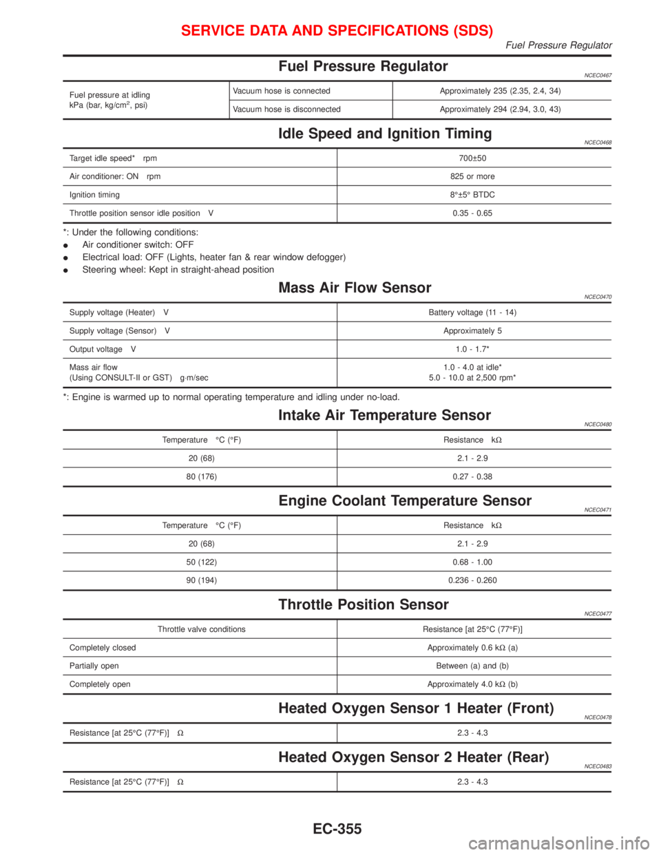
Fuel Pressure RegulatorNCEC0467
Fuel pressure at idling
kPa (bar, kg/cm2, psi)Vacuum hose is connected Approximately 235 (2.35, 2.4, 34)
Vacuum hose is disconnected Approximately 294 (2.94, 3.0, 43)
Idle Speed and Ignition TimingNCEC0468
Target idle speed* rpm700 50
Air conditioner: ON rpm825 or more
Ignition timing8É 5É BTDC
Throttle position sensor idle position V 0.35 - 0.65
*: Under the following conditions:
IAir conditioner switch: OFF
IElectrical load: OFF (Lights, heater fan & rear window defogger)
ISteering wheel: Kept in straight-ahead position
Mass Air Flow SensorNCEC0470
Supply voltage (Heater) VBattery voltage (11 - 14)
Supply voltage (Sensor) VApproximately 5
Output voltage V1.0 - 1.7*
Mass air flow
(Using CONSULT-II or GST) g×m/sec1.0 - 4.0 at idle*
5.0 - 10.0 at 2,500 rpm*
*: Engine is warmed up to normal operating temperature and idling under no-load.
Intake Air Temperature SensorNCEC0480
Temperature ÉC (ÉF) Resistance kW
20 (68) 2.1 - 2.9
80 (176) 0.27 - 0.38
Engine Coolant Temperature SensorNCEC0471
Temperature ÉC (ÉF) Resistance kW
20 (68) 2.1 - 2.9
50 (122) 0.68 - 1.00
90 (194) 0.236 - 0.260
Throttle Position SensorNCEC0477
Throttle valve conditions Resistance [at 25ÉC (77ÉF)]
Completely closedApproximately 0.6 kW(a)
Partially openBetween (a) and (b)
Completely openApproximately 4.0 kW(b)
Heated Oxygen Sensor 1 Heater (Front)NCEC0478
Resistance [at 25ÉC (77ÉF)]W2.3 - 4.3
Heated Oxygen Sensor 2 Heater (Rear)NCEC0483
Resistance [at 25ÉC (77ÉF)]W2.3 - 4.3
SERVICE DATA AND SPECIFICATIONS (SDS)
Fuel Pressure Regulator
EC-355
Page 801 of 2267
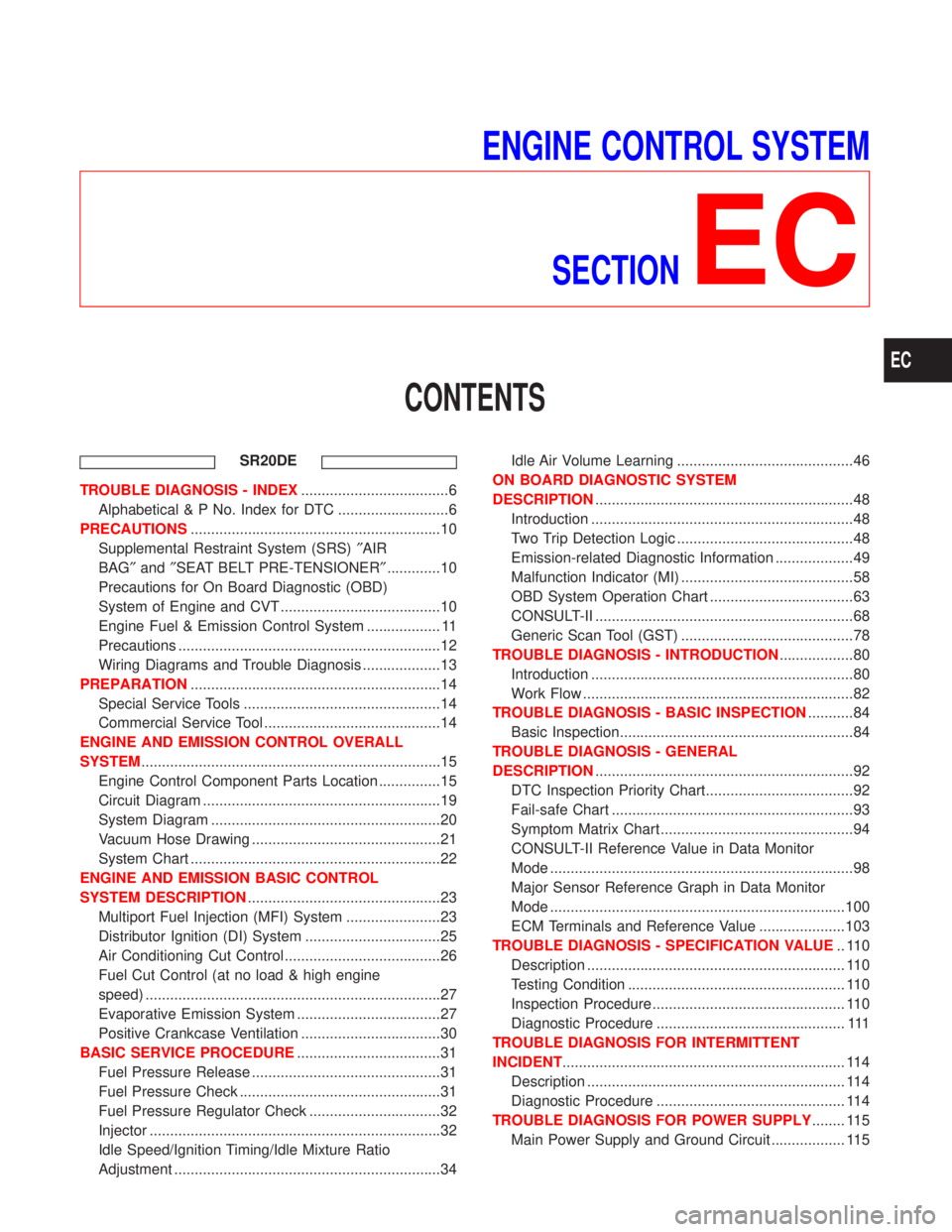
ENGINE CONTROL SYSTEM
SECTION
EC
CONTENTS
SR20DE
TROUBLE DIAGNOSIS - INDEX....................................6
Alphabetical & P No. Index for DTC ...........................6
PRECAUTIONS.............................................................10
Supplemental Restraint System (SRS)²AIR
BAG²and²SEAT BELT PRE-TENSIONER².............10
Precautions for On Board Diagnostic (OBD)
System of Engine and CVT .......................................10
Engine Fuel & Emission Control System .................. 11
Precautions ................................................................12
Wiring Diagrams and Trouble Diagnosis ...................13
PREPARATION.............................................................14
Special Service Tools ................................................14
Commercial Service Tool ...........................................14
ENGINE AND EMISSION CONTROL OVERALL
SYSTEM.........................................................................15
Engine Control Component Parts Location ...............15
Circuit Diagram ..........................................................19
System Diagram ........................................................20
Vacuum Hose Drawing ..............................................21
System Chart .............................................................22
ENGINE AND EMISSION BASIC CONTROL
SYSTEM DESCRIPTION...............................................23
Multiport Fuel Injection (MFI) System .......................23
Distributor Ignition (DI) System .................................25
Air Conditioning Cut Control ......................................26
Fuel Cut Control (at no load & high engine
speed) ........................................................................27
Evaporative Emission System ...................................27
Positive Crankcase Ventilation ..................................30
BASIC SERVICE PROCEDURE...................................31
Fuel Pressure Release ..............................................31
Fuel Pressure Check .................................................31
Fuel Pressure Regulator Check ................................32
Injector .......................................................................32
Idle Speed/Ignition Timing/Idle Mixture Ratio
Adjustment .................................................................34Idle Air Volume Learning ...........................................46
ON BOARD DIAGNOSTIC SYSTEM
DESCRIPTION...............................................................48
Introduction ................................................................48
Two Trip Detection Logic ...........................................48
Emission-related Diagnostic Information ...................49
Malfunction Indicator (MI) ..........................................58
OBD System Operation Chart ...................................63
CONSULT-II ...............................................................68
Generic Scan Tool (GST) ..........................................78
TROUBLE DIAGNOSIS - INTRODUCTION..................80
Introduction ................................................................80
Work Flow ..................................................................82
TROUBLE DIAGNOSIS - BASIC INSPECTION...........84
Basic Inspection.........................................................84
TROUBLE DIAGNOSIS - GENERAL
DESCRIPTION...............................................................92
DTC Inspection Priority Chart....................................92
Fail-safe Chart ...........................................................93
Symptom Matrix Chart ...............................................94
CONSULT-II Reference Value in Data Monitor
Mode ..........................................................................98
Major Sensor Reference Graph in Data Monitor
Mode ........................................................................100
ECM Terminals and Reference Value .....................103
TROUBLE DIAGNOSIS - SPECIFICATION VALUE.. 110
Description ............................................................... 110
Testing Condition ..................................................... 110
Inspection Procedure ............................................... 110
Diagnostic Procedure .............................................. 111
TROUBLE DIAGNOSIS FOR INTERMITTENT
INCIDENT..................................................................... 114
Description ............................................................... 114
Diagnostic Procedure .............................................. 114
TROUBLE DIAGNOSIS FOR POWER SUPPLY........ 115
Main Power Supply and Ground Circuit .................. 115
EC
Page 805 of 2267
CONSULT-II Reference Value in Data Monitor
Mode ........................................................................306
ECM Terminals and Reference Value .....................306
Wiring Diagram ........................................................308
Diagnostic Procedure ..............................................309
Component Inspection .............................................310
START SIGNAL...........................................................312
CONSULT-II Reference Value in Data Monitor
Mode ........................................................................312
ECM Terminals and Reference Value .....................312
Wiring Diagram ........................................................313
Diagnostic Procedure ..............................................314
FUEL PUMP.................................................................316
System Description ..................................................316
Component Description ...........................................316
CONSULT-II Reference Value in Data Monitor
Mode ........................................................................316
ECM Terminals and Reference Value .....................316
Wiring Diagram ........................................................317
Diagnostic Procedure ..............................................318
Component Inspection .............................................320
POWER STEERING OIL PRESSURE SWITCH.........321
Component Description ...........................................321
CONSULT-II Reference Value in Data Monitor
Mode ........................................................................321
ECM Terminals and Reference Value .....................321
Wiring Diagram ........................................................322Diagnostic Procedure ..............................................323
Component Inspection .............................................324
ELECTRICAL LOAD SIGNAL.....................................325
CONSULT-II Reference Value in Data Monitor
Mode ........................................................................325
ECM Terminals and Reference Value .....................325
Wiring Diagram ........................................................326
MI & DATA LINK CONNECTORS..............................329
Wiring Diagram ........................................................329
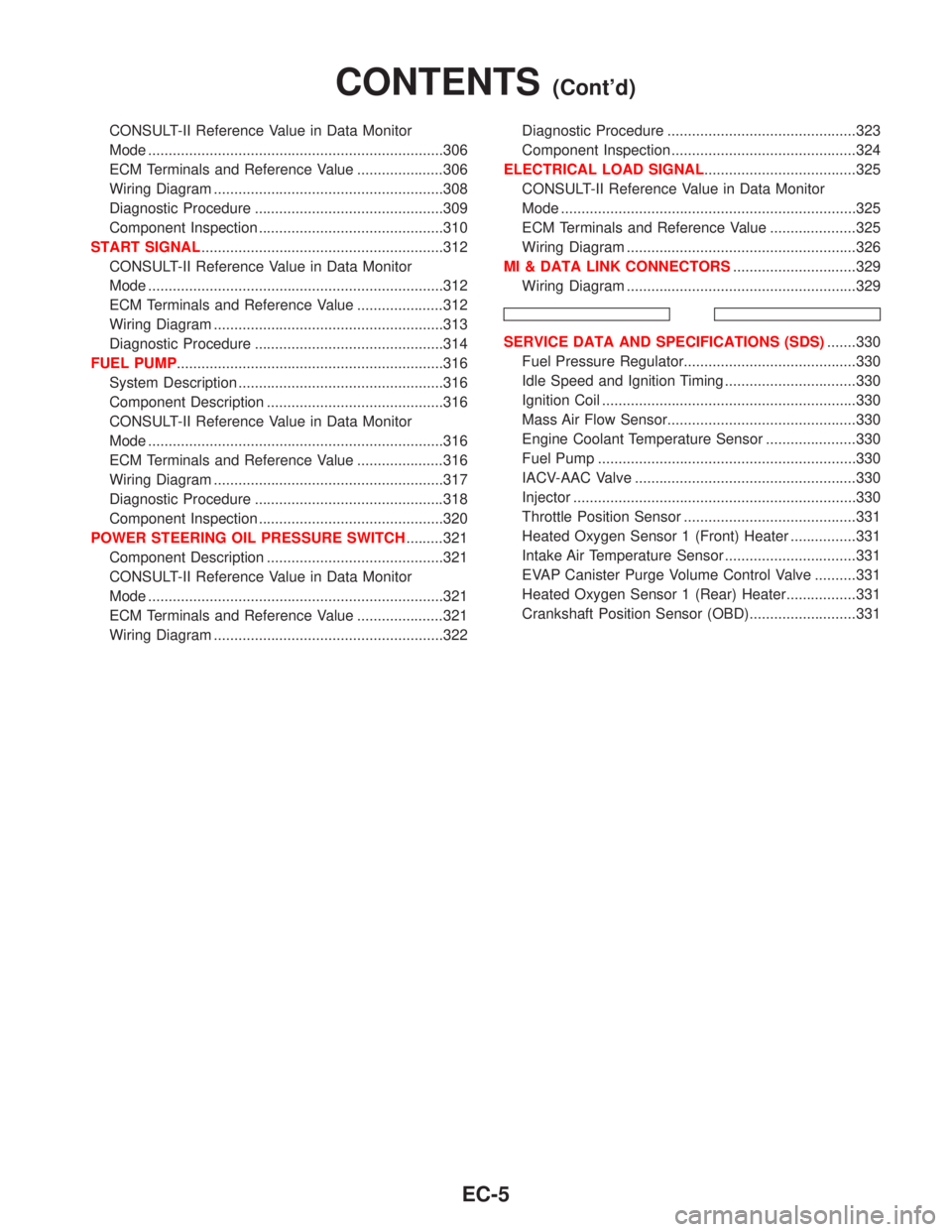
SERVICE DATA AND SPECIFICATIONS (SDS).......330
Fuel Pressure Regulator..........................................330
Idle Speed and Ignition Timing ................................330
Ignition Coil ..............................................................330
Mass Air Flow Sensor..............................................330
Engine Coolant Temperature Sensor ......................330
Fuel Pump ...............................................................330
IACV-AAC Valve ......................................................330
Injector .....................................................................330
Throttle Position Sensor ..........................................331
Heated Oxygen Sensor 1 (Front) Heater ................331
Intake Air Temperature Sensor ................................331
EVAP Canister Purge Volume Control Valve ..........331
Heated Oxygen Sensor 1 (Rear) Heater.................331
Crankshaft Position Sensor (OBD)..........................331
CONTENTS(Cont'd)
EC-5
Page 814 of 2267
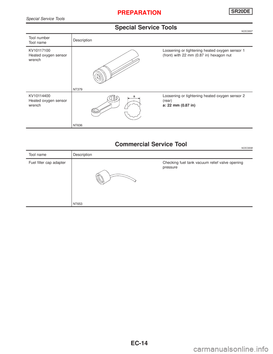
Special Service ToolsNCEC0007
Tool number
Tool nameDescription
KV10117100
Heated oxygen sensor
wrench
NT379
Loosening or tightening heated oxygen sensor 1
(front) with 22 mm (0.87 in) hexagon nut
KV10114400
Heated oxygen sensor
wrench
NT636
Loosening or tightening heated oxygen sensor 2
(rear)
a: 22 mm (0.87 in)
Commercial Service ToolNCEC0008
Tool name Description
Fuel filler cap adapter
NT653
Checking fuel tank vacuum relief valve opening
pressure
PREPARATIONSR20DE
Special Service Tools
EC-14
Page 817 of 2267
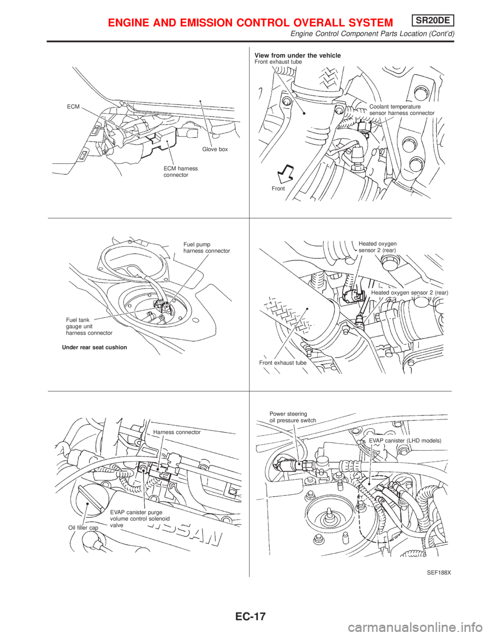
SEF188X ECM
ECM harness
connectorGlove box
View from under the vehicleFront exhaust tube
Coolant temperature
sensor harness connector
Front
Fuel pump
harness connector
Fuel tank
gauge unit
harness connector
Under rear seat cushion
Front exhaust tubeHeated oxygen
sensor 2 (rear)
Heated oxygen sensor 2 (rear)
Harness connector
EVAP canister purge
volume control solenoid
valve
Oil filler capPower steering
oil pressure switch
EVAP canister (LHD models)
ENGINE AND EMISSION CONTROL OVERALL SYSTEMSR20DE
Engine Control Component Parts Location (Cont'd)
EC-17
Page 818 of 2267
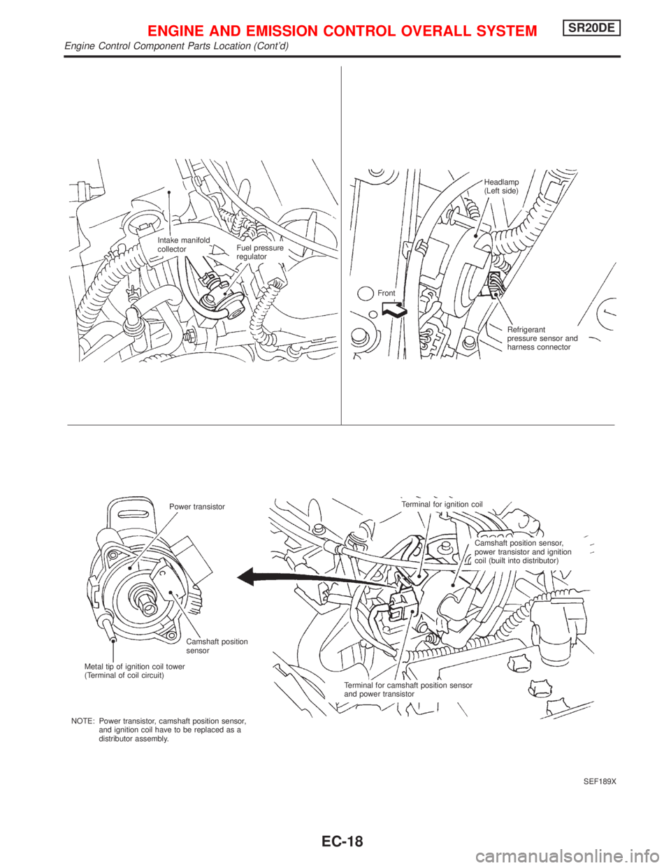
SEF189X Intake manifold
collectorFuel pressure
regulatorHeadlamp
(Left side)
Front
Refrigerant
pressure sensor and
harness connector
Power transistorTerminal for ignition coil
Camshaft position sensor,
power transistor and ignition
coil (built into distributor)
Terminal for camshaft position sensor
and power transistor Camshaft position
sensor
Metal tip of ignition coil tower
(Terminal of coil circuit)
NOTE: Power transistor, camshaft position sensor,
and ignition coil have to be replaced as a
distributor assembly.
ENGINE AND EMISSION CONTROL OVERALL SYSTEMSR20DE
Engine Control Component Parts Location (Cont'd)
EC-18
Page 821 of 2267
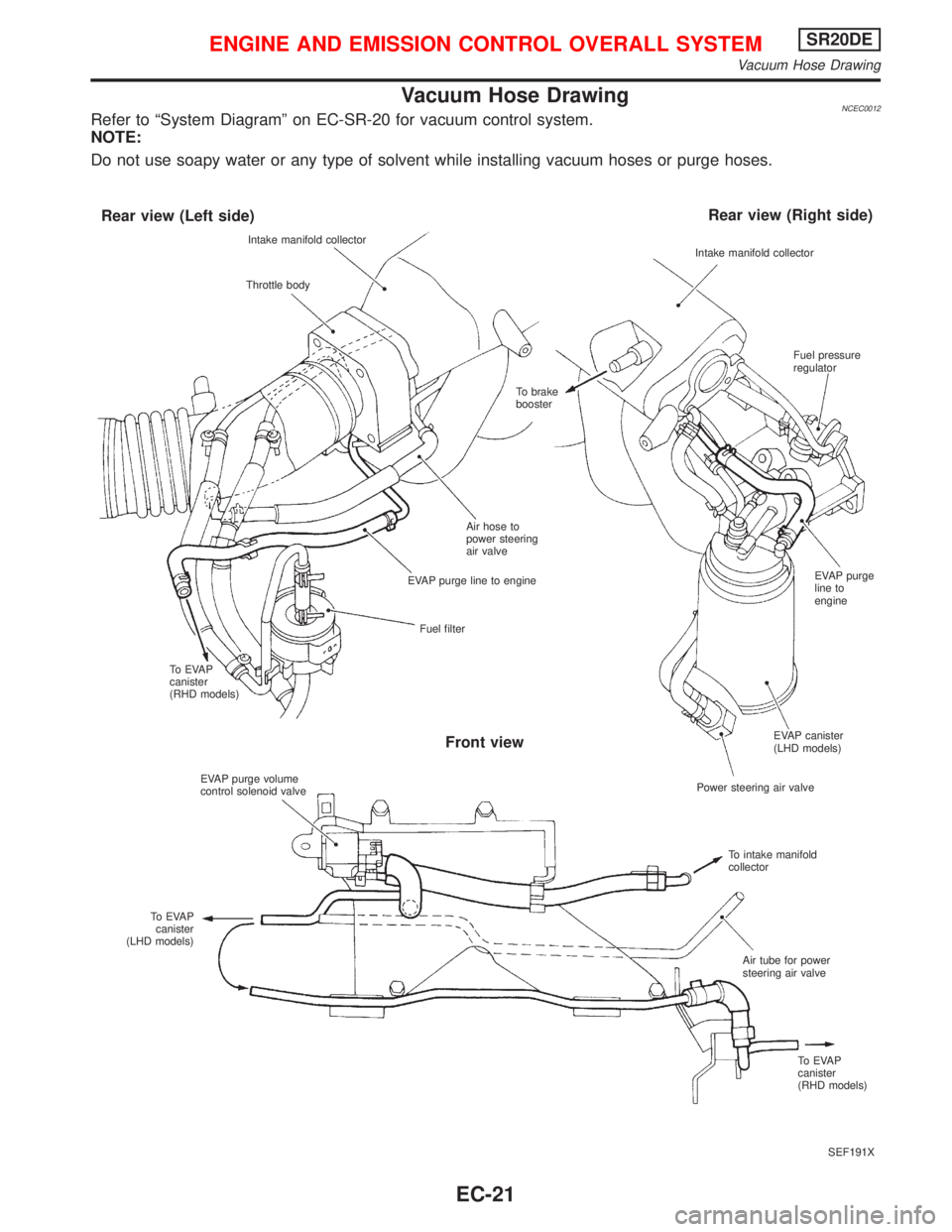
Vacuum Hose DrawingNCEC0012Refer to ªSystem Diagramº on EC-SR-20 for vacuum control system.
NOTE:
Do not use soapy water or any type of solvent while installing vacuum hoses or purge hoses.
SEF191X Intake manifold collector
Throttle body
Rear view (Left side)Rear view (Right side)
Intake manifold collector
Fuel pressure
regulator
To brake
booster
Air hose to
power steering
air valve
EVAP purge line to engine
Fuel filter
To EVAP
canister
(RHD models)
EVAP purge volume
control solenoid valve
To EVAP
canister
(LHD models)
Front view
EVAP purge
line to
engine
EVAP canister
(LHD models)
Power steering air valve
To intake manifold
collector
Air tube for power
steering air valve
To EVAP
canister
(RHD models)
ENGINE AND EMISSION CONTROL OVERALL SYSTEMSR20DE
Vacuum Hose Drawing
EC-21
Page 822 of 2267
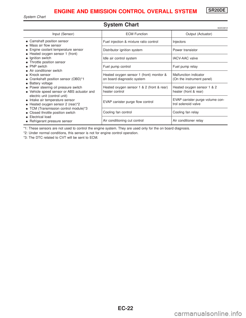
System ChartNCEC0013
Input (Sensor) ECM Function Output (Actuator)
ICamshaft position sensor
IMass air flow sensor
IEngine coolant temperature sensor
IHeated oxygen sensor 1 (front)
IIgnition switch
IThrottle position sensor
IPNP switch
IAir conditioner switch
IKnock sensor
ICrankshaft position sensor (OBD)*1
IBattery voltage
IPower steering oil pressure switch
IVehicle speed sensor or ABS actuator and
electric unit (control unit)
IIntake air temperature sensor
IHeated oxygen sensor 2 (rear)*2
ITCM (Transmission control module)*3
IClosed throttle position switch
IElectrical load
IRefrigerant pressure sensorFuel injection & mixture ratio control Injectors
Distributor ignition system Power transistor
Idle air control system IACV-AAC valve
Fuel pump control Fuel pump relay
Heated oxygen sensor 1 (front) monitor &
on board diagnostic systemMalfunction indicator
(On the instrument panel)
Heated oxygen sensor1&2(front & rear)
heater controlHeated oxygen sensor1&2
heater (front & rear)
EVAP canister purge flow controlEVAP canister purge volume con-
trol solenoid valve
Cooling fan control Cooling fan relay
Air conditioning cut control Air conditioner relay
*1: These sensors are not used to control the engine system. They are used only for the on board diagnosis.
*2: Under normal conditions, this sensor is not for engine control operation.
*3: The DTC related to CVT will be sent to ECM.
ENGINE AND EMISSION CONTROL OVERALL SYSTEMSR20DE
System Chart
EC-22