1999 NISSAN PRIMERA fuel pressure
[x] Cancel search: fuel pressurePage 957 of 2267
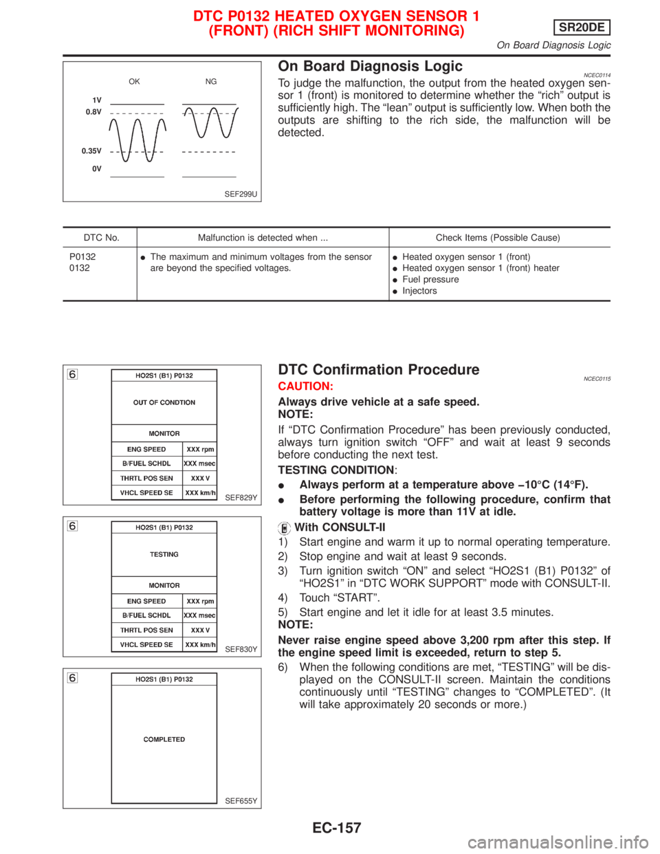
On Board Diagnosis LogicNCEC0114To judge the malfunction, the output from the heated oxygen sen-
sor 1 (front) is monitored to determine whether the ªrichº output is
sufficiently high. The ªleanº output is sufficiently low. When both the
outputs are shifting to the rich side, the malfunction will be
detected.
DTC No. Malfunction is detected when ... Check Items (Possible Cause)
P0132
0132IThe maximum and minimum voltages from the sensor
are beyond the specified voltages.IHeated oxygen sensor 1 (front)
IHeated oxygen sensor 1 (front) heater
IFuel pressure
IInjectors
DTC Confirmation ProcedureNCEC0115CAUTION:
Always drive vehicle at a safe speed.
NOTE:
If ªDTC Confirmation Procedureº has been previously conducted,
always turn ignition switch ªOFFº and wait at least 9 seconds
before conducting the next test.
TESTING CONDITION:
IAlways perform at a temperature above þ10ÉC (14ÉF).
IBefore performing the following procedure, confirm that
battery voltage is more than 11V at idle.
With CONSULT-II
1) Start engine and warm it up to normal operating temperature.
2) Stop engine and wait at least 9 seconds.
3) Turn ignition switch ªONº and select ªHO2S1 (B1) P0132º of
ªHO2S1º in ªDTC WORK SUPPORTº mode with CONSULT-II.
4) Touch ªSTARTº.
5) Start engine and let it idle for at least 3.5 minutes.
NOTE:
Never raise engine speed above 3,200 rpm after this step. If
the engine speed limit is exceeded, return to step 5.
6) When the following conditions are met, ªTESTINGº will be dis-
played on the CONSULT-II screen. Maintain the conditions
continuously until ªTESTINGº changes to ªCOMPLETEDº. (It
will take approximately 20 seconds or more.)
SEF299U OK NG
1V
0.8V
0.35V
0V
SEF829Y
SEF830Y
SEF655Y
DTC P0132 HEATED OXYGEN SENSOR 1
(FRONT) (RICH SHIFT MONITORING)SR20DE
On Board Diagnosis Logic
EC-157
Page 963 of 2267
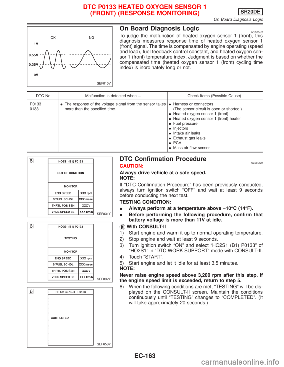
On Board Diagnosis LogicNCEC0122To judge the malfunction of heated oxygen sensor 1 (front), this
diagnosis measures response time of heated oxygen sensor 1
(front) signal. The time is compensated by engine operating (speed
and load), fuel feedback control constant, and heated oxygen sen-
sor 1 (front) temperature index. Judgment is based on whether the
compensated time (heated oxygen sensor 1 (front) cycling time
index) is inordinately long or not.
DTC No. Malfunction is detected when ... Check Items (Possible Cause)
P0133
0133IThe response of the voltage signal from the sensor takes
more than the specified time.IHarness or connectors
(The sensor circuit is open or shorted.)
IHeated oxygen sensor 1 (front)
IHeated oxygen sensor 1 (front) heater
IFuel pressure
IInjectors
IIntake air leaks
IExhaust gas leaks
IPCV
IMass air flow sensor
DTC Confirmation ProcedureNCEC0123CAUTION:
Always drive vehicle at a safe speed.
NOTE:
If ªDTC Confirmation Procedureº has been previously conducted,
always turn ignition switch ªOFFº and wait at least 9 seconds
before conducting the next test.
TESTING CONDITION:
IAlways perform at a temperature above þ10ÉC (14ÉF).
IBefore performing the following procedure, confirm that
battery voltage is more than 11V at idle.
With CONSULT-II
1) Start engine and warm it up to normal operating temperature.
2) Stop engine and wait at least 9 seconds.
3) Turn ignition switch ªONº and select ªHO2S1 (B1) P0133º of
ªHO2S1º in ªDTC WORK SUPPORTº mode with CONSULT-II.
4) Touch ªSTARTº.
5) Start engine and let it idle for at least 3.5 minutes.
NOTE:
Never raise engine speed above 3,200 rpm after this step. If
the engine speed limit is exceeded, return to step 5.
6) When the following conditions are met, ªTESTINGº will be dis-
played on the CONSULT-II screen. Maintain the conditions
continuously until ªTESTINGº changes to ªCOMPLETEDº. (It
will take approximately 20 seconds.)
SEF010V
SEF831Y
SEF832Y
SEF658Y
DTC P0133 HEATED OXYGEN SENSOR 1
(FRONT) (RESPONSE MONITORING)SR20DE
On Board Diagnosis Logic
EC-163
Page 980 of 2267
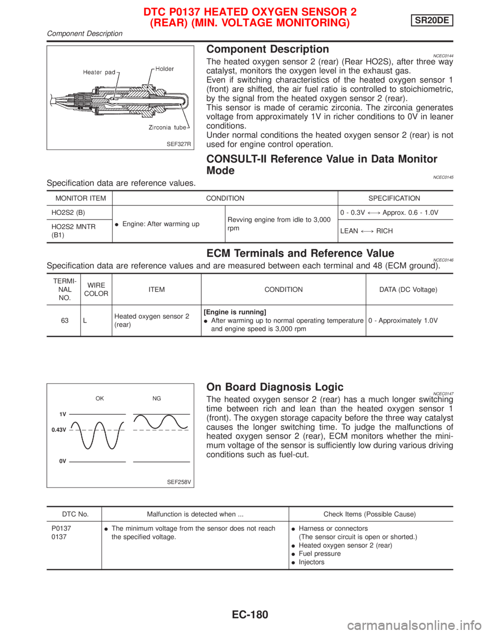
Component DescriptionNCEC0144The heated oxygen sensor 2 (rear) (Rear HO2S), after three way
catalyst, monitors the oxygen level in the exhaust gas.
Even if switching characteristics of the heated oxygen sensor 1
(front) are shifted, the air fuel ratio is controlled to stoichiometric,
by the signal from the heated oxygen sensor 2 (rear).
This sensor is made of ceramic zirconia. The zirconia generates
voltage from approximately 1V in richer conditions to 0V in leaner
conditions.
Under normal conditions the heated oxygen sensor 2 (rear) is not
used for engine control operation.
CONSULT-II Reference Value in Data Monitor
Mode
NCEC0145Specification data are reference values.
MONITOR ITEM CONDITION SPECIFICATION
HO2S2 (B)
IEngine: After warming upRevving engine from idle to 3,000
rpm0 - 0.3V+,Approx. 0.6 - 1.0V
HO2S2 MNTR
(B1)LEAN+,RICH
ECM Terminals and Reference ValueNCEC0146Specification data are reference values and are measured between each terminal and 48 (ECM ground).
TERMI-
NAL
NO.WIRE
COLORITEM CONDITION DATA (DC Voltage)
63 LHeated oxygen sensor 2
(rear)[Engine is running]
IAfter warming up to normal operating temperature
and engine speed is 3,000 rpm0 - Approximately 1.0V
On Board Diagnosis LogicNCEC0147The heated oxygen sensor 2 (rear) has a much longer switching
time between rich and lean than the heated oxygen sensor 1
(front). The oxygen storage capacity before the three way catalyst
causes the longer switching time. To judge the malfunctions of
heated oxygen sensor 2 (rear), ECM monitors whether the mini-
mum voltage of the sensor is sufficiently low during various driving
conditions such as fuel-cut.
DTC No. Malfunction is detected when ... Check Items (Possible Cause)
P0137
0137IThe minimum voltage from the sensor does not reach
the specified voltage.IHarness or connectors
(The sensor circuit is open or shorted.)
IHeated oxygen sensor 2 (rear)
IFuel pressure
IInjectors
SEF327R
SEF258V OK NG
1V
0.43V
0V
DTC P0137 HEATED OXYGEN SENSOR 2
(REAR) (MIN. VOLTAGE MONITORING)SR20DE
Component Description
EC-180
Page 987 of 2267
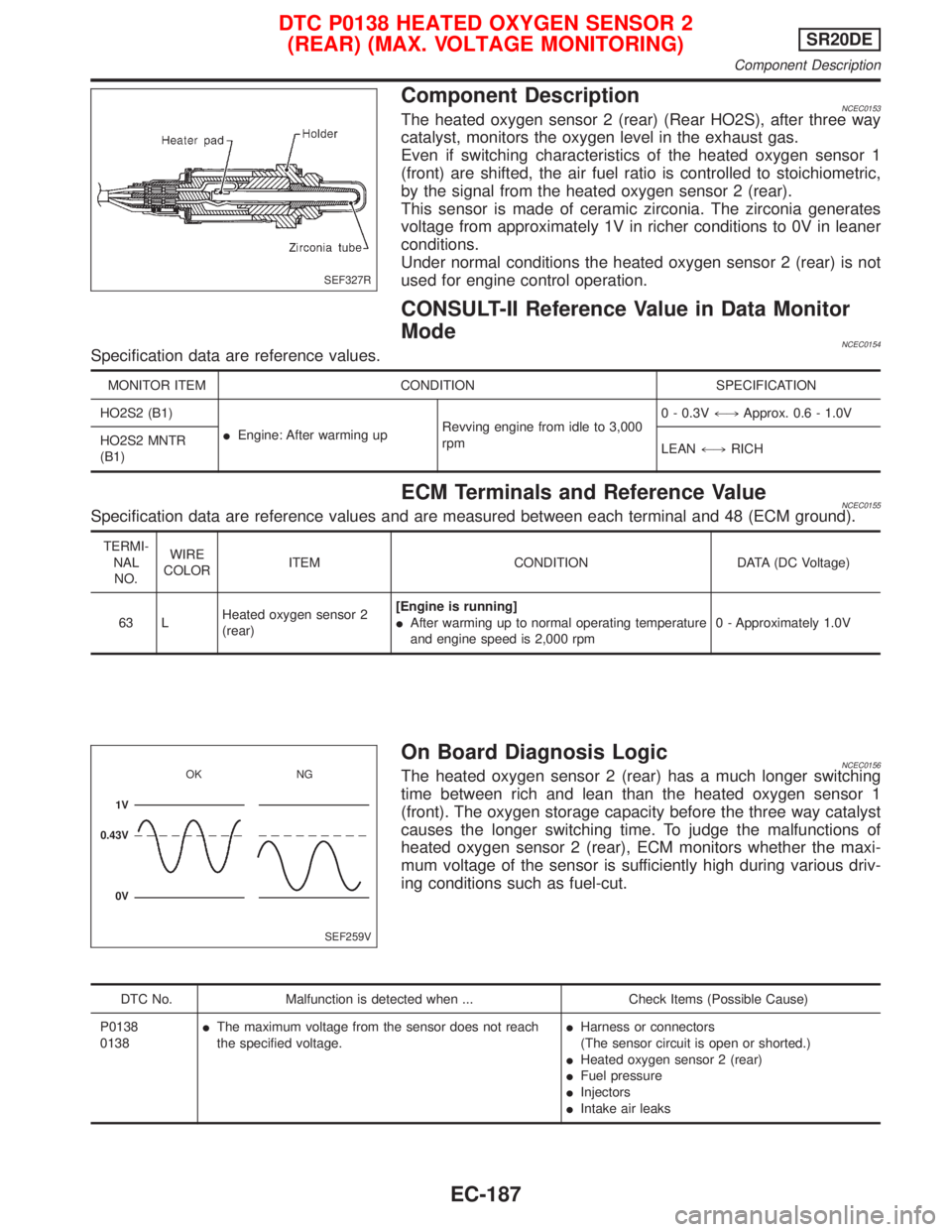
Component DescriptionNCEC0153The heated oxygen sensor 2 (rear) (Rear HO2S), after three way
catalyst, monitors the oxygen level in the exhaust gas.
Even if switching characteristics of the heated oxygen sensor 1
(front) are shifted, the air fuel ratio is controlled to stoichiometric,
by the signal from the heated oxygen sensor 2 (rear).
This sensor is made of ceramic zirconia. The zirconia generates
voltage from approximately 1V in richer conditions to 0V in leaner
conditions.
Under normal conditions the heated oxygen sensor 2 (rear) is not
used for engine control operation.
CONSULT-II Reference Value in Data Monitor
Mode
NCEC0154Specification data are reference values.
MONITOR ITEM CONDITION SPECIFICATION
HO2S2 (B1)
IEngine: After warming upRevving engine from idle to 3,000
rpm0 - 0.3V+,Approx. 0.6 - 1.0V
HO2S2 MNTR
(B1)LEAN+,RICH
ECM Terminals and Reference ValueNCEC0155Specification data are reference values and are measured between each terminal and 48 (ECM ground).
TERMI-
NAL
NO.WIRE
COLORITEM CONDITION DATA (DC Voltage)
63 LHeated oxygen sensor 2
(rear)[Engine is running]
IAfter warming up to normal operating temperature
and engine speed is 2,000 rpm0 - Approximately 1.0V
On Board Diagnosis LogicNCEC0156The heated oxygen sensor 2 (rear) has a much longer switching
time between rich and lean than the heated oxygen sensor 1
(front). The oxygen storage capacity before the three way catalyst
causes the longer switching time. To judge the malfunctions of
heated oxygen sensor 2 (rear), ECM monitors whether the maxi-
mum voltage of the sensor is sufficiently high during various driv-
ing conditions such as fuel-cut.
DTC No. Malfunction is detected when ... Check Items (Possible Cause)
P0138
0138IThe maximum voltage from the sensor does not reach
the specified voltage.IHarness or connectors
(The sensor circuit is open or shorted.)
IHeated oxygen sensor 2 (rear)
IFuel pressure
IInjectors
IIntake air leaks
SEF327R
SEF259V OK NG
1V
0.43V
0V
DTC P0138 HEATED OXYGEN SENSOR 2
(REAR) (MAX. VOLTAGE MONITORING)SR20DE
Component Description
EC-187
Page 994 of 2267
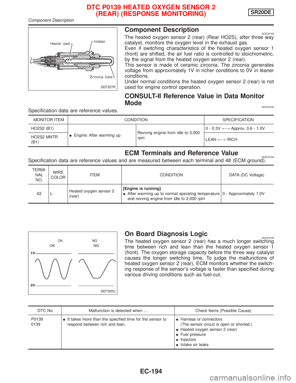
Component DescriptionNCEC0162The heated oxygen sensor 2 (rear) (Rear HO2S), after three way
catalyst, monitors the oxygen level in the exhaust gas.
Even if switching characteristics of the heated oxygen sensor 1
(front) are shifted, the air fuel ratio is controlled to stoichiometric,
by the signal from the heated oxygen sensor 2 (rear).
This sensor is made of ceramic zirconia. The zirconia generates
voltage from approximately 1V in richer conditions to 0V in leaner
conditions.
Under normal conditions the heated oxygen sensor 2 (rear) is not
used for engine control operation.
CONSULT-II Reference Value in Data Monitor
Mode
NCEC0163Specification data are reference values.
MONITOR ITEM CONDITION SPECIFICATION
HO2S2 (B1)
IEngine: After warming upRevving engine from idle to 3,000
rpm0 - 0.3V+,Approx. 0.6 - 1.0V
HO2S2 MNTR
(B1)LEAN+,RICH
ECM Terminals and Reference ValueNCEC0164Specification data are reference values and are measured between each terminal and 48 (ECM ground).
TERMI-
NAL
NO.WIRE
COLORITEM CONDITION DATA (DC Voltage)
63 LHeated oxygen sensor 2
(rear)[Engine is running]
IAfter warming up to normal operating temperature
and revving engine from idle to 2,000 rpm0 - Approximately 1.0V
On Board Diagnosis LogicNCEC0165The heated oxygen sensor 2 (rear) has a much longer switching
time between rich and lean than the heated oxygen sensor 1
(front). The oxygen storage capacity before the three way catalyst
causes the longer switching time. To judge the malfunctions of
heated oxygen sensor 2 (rear), ECM monitors whether the switch-
ing response of the sensor's voltage is faster than specified during
various driving conditions such as fuel-cut.
DTC No. Malfunction is detected when ... Check Items (Possible Cause)
P0139
0139IIt takes more than the specified time for the sensor to
respond between rich and lean.IHarness or connectors
(The sensor circuit is open or shorted.)
IHeated oxygen sensor 2 (rear)
IFuel pressure
IInjectors
IIntake air leaks
SEF327R
SEF302U OK NG
DTC P0139 HEATED OXYGEN SENSOR 2
(REAR) (RESPONSE MONITORING)SR20DE
Component Description
EC-194
Page 1012 of 2267
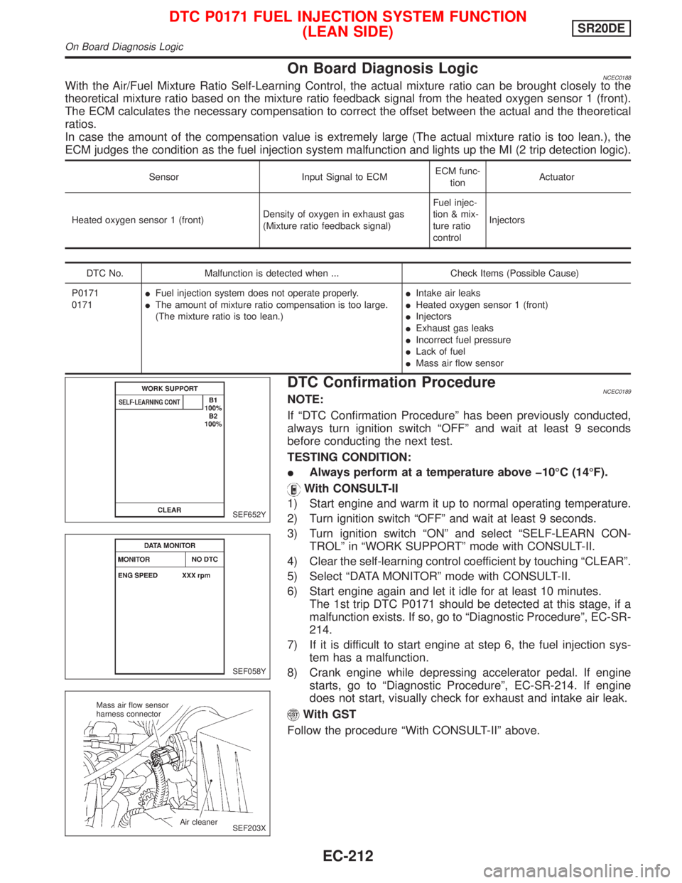
On Board Diagnosis LogicNCEC0188With the Air/Fuel Mixture Ratio Self-Learning Control, the actual mixture ratio can be brought closely to the
theoretical mixture ratio based on the mixture ratio feedback signal from the heated oxygen sensor 1 (front).
The ECM calculates the necessary compensation to correct the offset between the actual and the theoretical
ratios.
In case the amount of the compensation value is extremely large (The actual mixture ratio is too lean.), the
ECM judges the condition as the fuel injection system malfunction and lights up the MI (2 trip detection logic).
Sensor Input Signal to ECMECM func-
tionActuator
Heated oxygen sensor 1 (front)Density of oxygen in exhaust gas
(Mixture ratio feedback signal)Fuel injec-
tion & mix-
ture ratio
controlInjectors
DTC No. Malfunction is detected when ... Check Items (Possible Cause)
P0171
0171IFuel injection system does not operate properly.
IThe amount of mixture ratio compensation is too large.
(The mixture ratio is too lean.)IIntake air leaks
IHeated oxygen sensor 1 (front)
IInjectors
IExhaust gas leaks
IIncorrect fuel pressure
ILack of fuel
IMass air flow sensor
DTC Confirmation ProcedureNCEC0189NOTE:
If ªDTC Confirmation Procedureº has been previously conducted,
always turn ignition switch ªOFFº and wait at least 9 seconds
before conducting the next test.
TESTING CONDITION:
IAlways perform at a temperature above þ10ÉC (14ÉF).
With CONSULT-II
1) Start engine and warm it up to normal operating temperature.
2) Turn ignition switch ªOFFº and wait at least 9 seconds.
3) Turn ignition switch ªONº and select ªSELF-LEARN CON-
TROLº in ªWORK SUPPORTº mode with CONSULT-II.
4) Clear the self-learning control coefficient by touching ªCLEARº.
5) Select ªDATA MONITORº mode with CONSULT-II.
6) Start engine again and let it idle for at least 10 minutes.
The 1st trip DTC P0171 should be detected at this stage, if a
malfunction exists. If so, go to ªDiagnostic Procedureº, EC-SR-
214.
7) If it is difficult to start engine at step 6, the fuel injection sys-
tem has a malfunction.
8) Crank engine while depressing accelerator pedal. If engine
starts, go to ªDiagnostic Procedureº, EC-SR-214. If engine
does not start, visually check for exhaust and intake air leak.
With GST
Follow the procedure ªWith CONSULT-IIº above.
SEF652Y
SEF058Y
SEF203X Mass air flow sensor
harness connector
Air cleaner
DTC P0171 FUEL INJECTION SYSTEM FUNCTION
(LEAN SIDE)SR20DE
On Board Diagnosis Logic
EC-212
Page 1015 of 2267
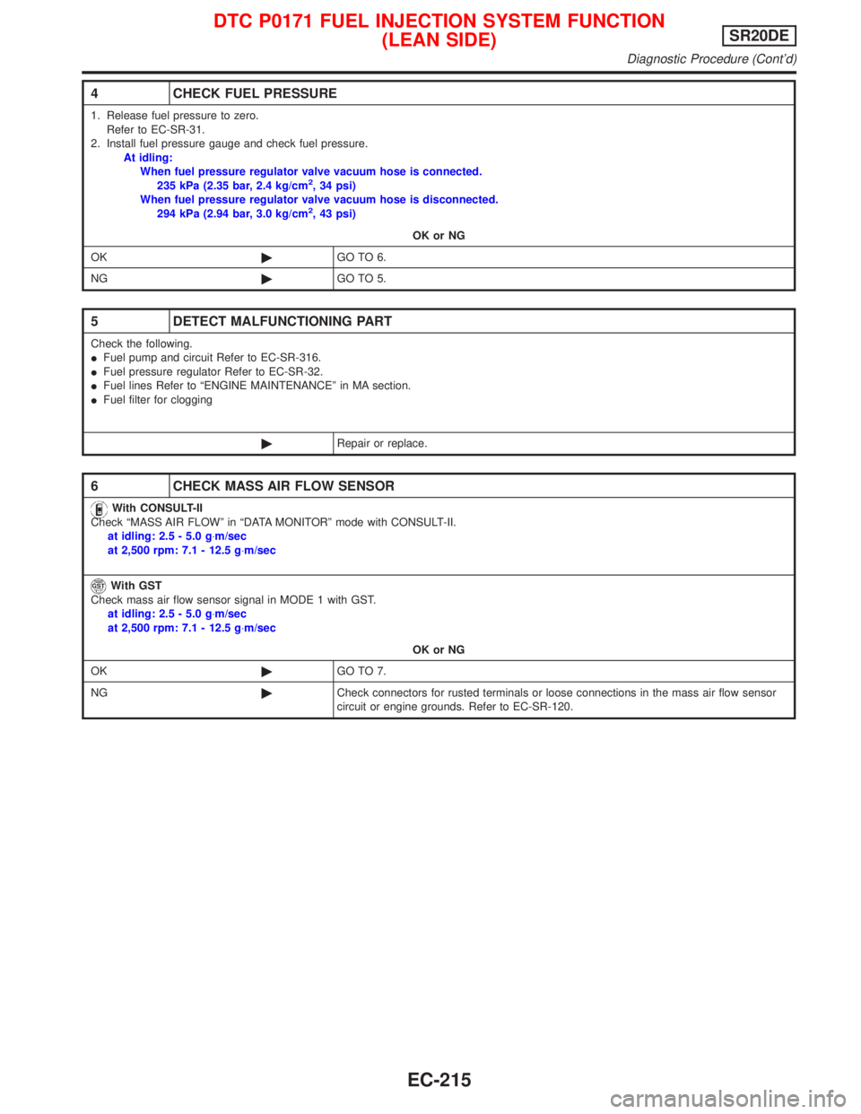
4 CHECK FUEL PRESSURE
1. Release fuel pressure to zero.
Refer to EC-SR-31.
2. Install fuel pressure gauge and check fuel pressure.
At idling:
When fuel pressure regulator valve vacuum hose is connected.
235 kPa (2.35 bar, 2.4 kg/cm
2, 34 psi)
When fuel pressure regulator valve vacuum hose is disconnected.
294 kPa (2.94 bar, 3.0 kg/cm
2, 43 psi)
OK or NG
OK©GO TO 6.
NG©GO TO 5.
5 DETECT MALFUNCTIONING PART
Check the following.
IFuel pump and circuit Refer to EC-SR-316.
IFuel pressure regulator Refer to EC-SR-32.
IFuel lines Refer to ªENGINE MAINTENANCEº in MA section.
IFuel filter for clogging
©Repair or replace.
6 CHECK MASS AIR FLOW SENSOR
With CONSULT-II
Check ªMASS AIR FLOWº in ªDATA MONITORº mode with CONSULT-II.
at idling: 2.5 - 5.0 g×m/sec
at 2,500 rpm: 7.1 - 12.5 g×m/sec
With GST
Check mass air flow sensor signal in MODE 1 with GST.
at idling: 2.5 - 5.0 g×m/sec
at 2,500 rpm: 7.1 - 12.5 g×m/sec
OK or NG
OK©GO TO 7.
NG©Check connectors for rusted terminals or loose connections in the mass air flow sensor
circuit or engine grounds. Refer to EC-SR-120.
DTC P0171 FUEL INJECTION SYSTEM FUNCTION
(LEAN SIDE)SR20DE
Diagnostic Procedure (Cont'd)
EC-215
Page 1018 of 2267
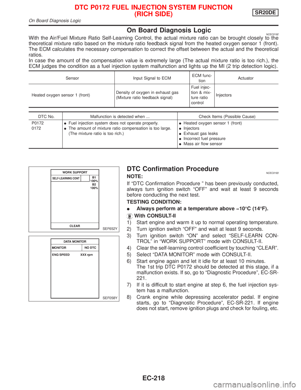
On Board Diagnosis LogicNCEC0192With the Air/Fuel Mixture Ratio Self-Learning Control, the actual mixture ratio can be brought closely to the
theoretical mixture ratio based on the mixture ratio feedback signal from the heated oxygen sensor 1 (front).
The ECM calculates the necessary compensation to correct the offset between the actual and the theoretical
ratios.
In case the amount of the compensation value is extremely large (The actual mixture ratio is too rich.), the
ECM judges the condition as a fuel injection system malfunction and lights up the MI (2 trip detection logic).
Sensor Input Signal to ECMECM func-
tionActuator
Heated oxygen sensor 1 (front)Density of oxygen in exhaust gas
(Mixture ratio feedback signal)Fuel injec-
tion & mix-
ture ratio
controlInjectors
DTC No. Malfunction is detected when ... Check Items (Possible Cause)
P0172
0172IFuel injection system does not operate properly.
IThe amount of mixture ratio compensation is too large.
(The mixture ratio is too rich.)IHeated oxygen sensor 1 (front)
IInjectors
IExhaust gas leaks
IIncorrect fuel pressure
IMass air flow sensor
DTC Confirmation ProcedureNCEC0193NOTE:
If ªDTC Confirmation Procedure º has been previously conducted,
always turn ignition switch ªOFFº and wait at least 9 seconds
before conducting the next test.
TESTING CONDITION:
IAlways perform at a temperature above þ10ÉC (14ÉF).
With CONSULT-II
1) Start engine and warm it up to normal operating temperature.
2) Turn ignition switch ªOFFº and wait at least 9 seconds.
3) Turn ignition switch ªONº and select ªSELF-LEARN CON-
TROLº in ªWORK SUPPORTº mode with CONSULT-II.
4) Clear the self-learning control coefficient by touching ªCLEARº.
5) Select ªDATA MONITORº mode with CONSULT-II.
6) Start engine again and let it idle for at least 10 minutes.
The 1st trip DTC P0172 should be detected at this stage, if a
malfunction exists. If so, go to ªDiagnostic Procedureº, EC-SR-
221.
7) If it is difficult to start engine at step 6, the fuel injection sys-
tem has a malfunction.
8) Crank engine while depressing accelerator pedal. If engine
starts, go to ªDiagnostic Procedureº, EC-SR-221. If engine
does not start, remove ignition plugs and check for fouling, etc.
SEF652Y
SEF058Y
DTC P0172 FUEL INJECTION SYSTEM FUNCTION
(RICH SIDE)SR20DE
On Board Diagnosis Logic
EC-218