1999 NISSAN PRIMERA fuel pressure
[x] Cancel search: fuel pressurePage 1647 of 2267
WARNING:
IPosition vehicle on a flat and solid surface.
IPlace chocks at front and back of rear wheels.
IDo not remove engine until exhaust system has com-
pletely cooled;
Otherwise, you may burn yourself and/or fire may break
out in fuel line.
IBefore disconnecting fuel hose, release fuel pressure
from fuel line.
Refer to ªReleasing Fuel Pressureº in EC section.
IBe sure to hoist engine and transaxle in a safe manner.
IFor engines not equipped with engine slingers, attach
slingers and bolts described in PARTS CATALOG.
CAUTION:
IWhen lifting engine, be sure to clear surrounding parts.
Use special care for accelerator cable, brake lines and
brake master cylinder.
IIn hoisting the engine, always use engine slingers in a
safe manner.
IWhen removing drive shaft, be careful not to damage
grease seal of transaxle.
Removal
1. Remove engine under cover and hood.
2. Drain coolant from both cylinder block, and radiator.
3. Drain engine oil.
4. Remove vacuum hoses, fuel hoses, wires, harness and con-
nectors.
5. Remove exhaust tubes, ball joints and drive shafts.
6. Remove radiator and fans.
7. Remove drive belts.
8. Remove alternator, compressor and power steering oil pump
from engine.
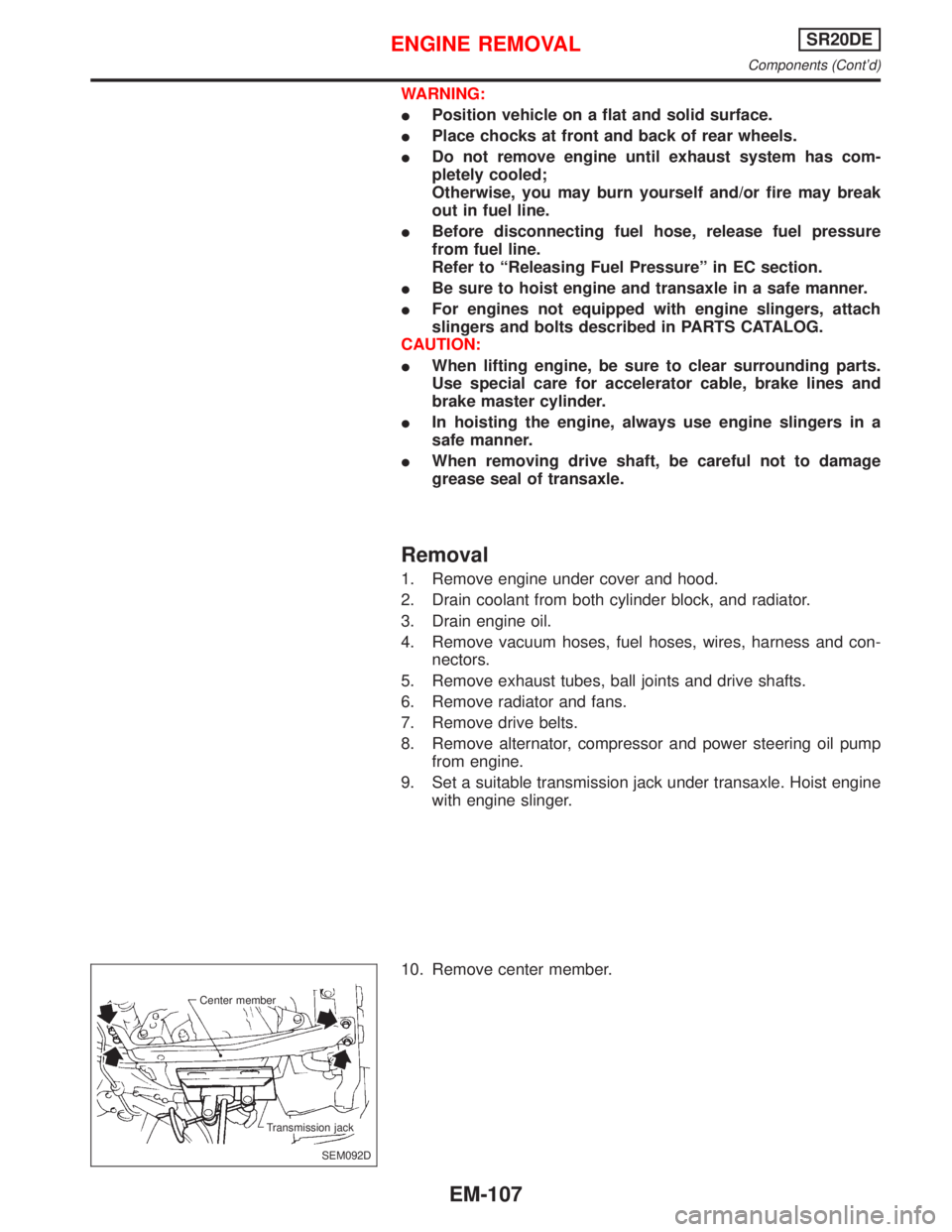
9. Set a suitable transmission jack under transaxle. Hoist engine
with engine slinger.
10. Remove center member.
SEM092D Center member
Transmission jack
ENGINE REMOVALSR20DE
Components (Cont'd)
EM-107
Page 1784 of 2267
WARNING:
When replacing fuel line parts, be sure to observe the following:
lDisplay a ªCAUTION: INFLAMMABLEº sign in workshop.
lDo not smoke while servicing fuel system. Keep open flames and sparks away from work area.
lBe sure to disconnect battery ground cable before conducting service operations.
lBe sure to furnish workshop with a CO2fire extinguisher.
lPour drained fuel into an explosion-proof container then ensure container lid is installed securely.
CAUTION:
lFor ECCS engine models, release fuel pressure from fuel line. Refer to EC section (ªFuel Pres-
sure Releaseº, ªBASIC SERVICE PROCEDUREº).
lDo not disconnect any fuel line unless absolutely necessary.
lPlug hose and pipe openings to prevent entry of dust or dirt.
lAlways replace top lid seal and hose clamps with new ones.
lDo not kink or twist hoses and tubes during installation.
lDo not tighten hose clamps excessively because this could cause damage to the hose.
lEnsure fuel check valve is installed in the correct orientation. Refer to EC section (ªFUEL CHECK
VALVEº, ªEVAPORATIVE EMISSION SYSTEMº).
lAfter installation, run engine and check for fuel leaks at connections.
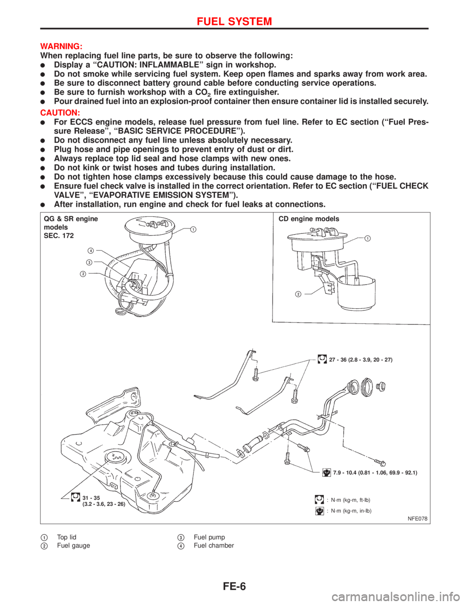
p1Top lid
p2Fuel gaugep3Fuel pump
p4Fuel chamber
NFE078
p1
QG & SR engine
models
SEC. 172
p4
p3
p2
CD engine models
p1
p2
27 - 36 (2.8 - 3.9, 20 - 27)
7.9 - 10.4 (0.81 - 1.06, 69.9 - 92.1)
31-35
(3.2 - 3.6, 23 - 26): N´m (kg-m, ft-lb)
: N´m (kg-m, in-lb)
FUEL SYSTEM
FE-6
Page 1785 of 2267
Fuel Pump and Gauge
REMOVAL
1. Release fuel pressure from fuel line.
Refer to EC section (ªFuel Pressure Releaseº, ªBASIC SER-
VICE PROCEDUREº).
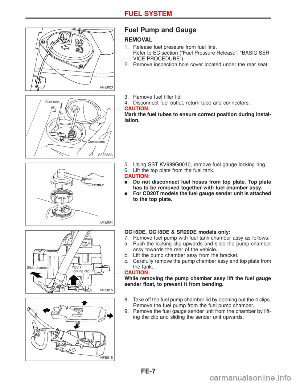
2. Remove inspection hole cover located under the rear seat.
3. Remove fuel filler lid.
4. Disconnect fuel outlet, return tube and connectors.
CAUTION:
Mark the fuel tubes to ensure correct position during instal-
lation.
5. Using SST KV999G0010, remove fuel gauge locking ring.
6. Lift the top plate from the fuel tank.
CAUTION:
lDo not disconnect fuel hoses from top plate. Top plate
has to be removed together with fuel chamber assy.
lFor CD20T models the fuel gauge sender unit is attached
to the top plate.
QG16DE, QG18DE & SR20DE models only:
7. Remove fuel pump with fuel tank chamber assy as follows:
a. Push the locking clip upwards and slide the pump chamber
assy towards the rear of the vehicle.
b. Lift the pump chamber assy from the bracket.
c. Carefully remove the pump chamber assy and top plate from
the tank.
CAUTION:
While removing the pump chamber assy lift the fuel gauge
sender float, to prevent it from bending.
8. Take off the fuel pump chamber lid by opening out the 4 clips.
Remove the fuel pump from the fuel pump chamber.
9. Remove the fuel gauge sender unit from the chamber by lift-
ing the clip and sliding the sender unit upwards.
NFE023
SFE385A Fuel tube
Connectors
UFE004
NFE015
.Slide chamber.PUSH
Locking clip
NFE016
FUEL SYSTEM
FE-7
Page 1801 of 2267
Precautions for Multiport Fuel Injection
System or Engine Control Module
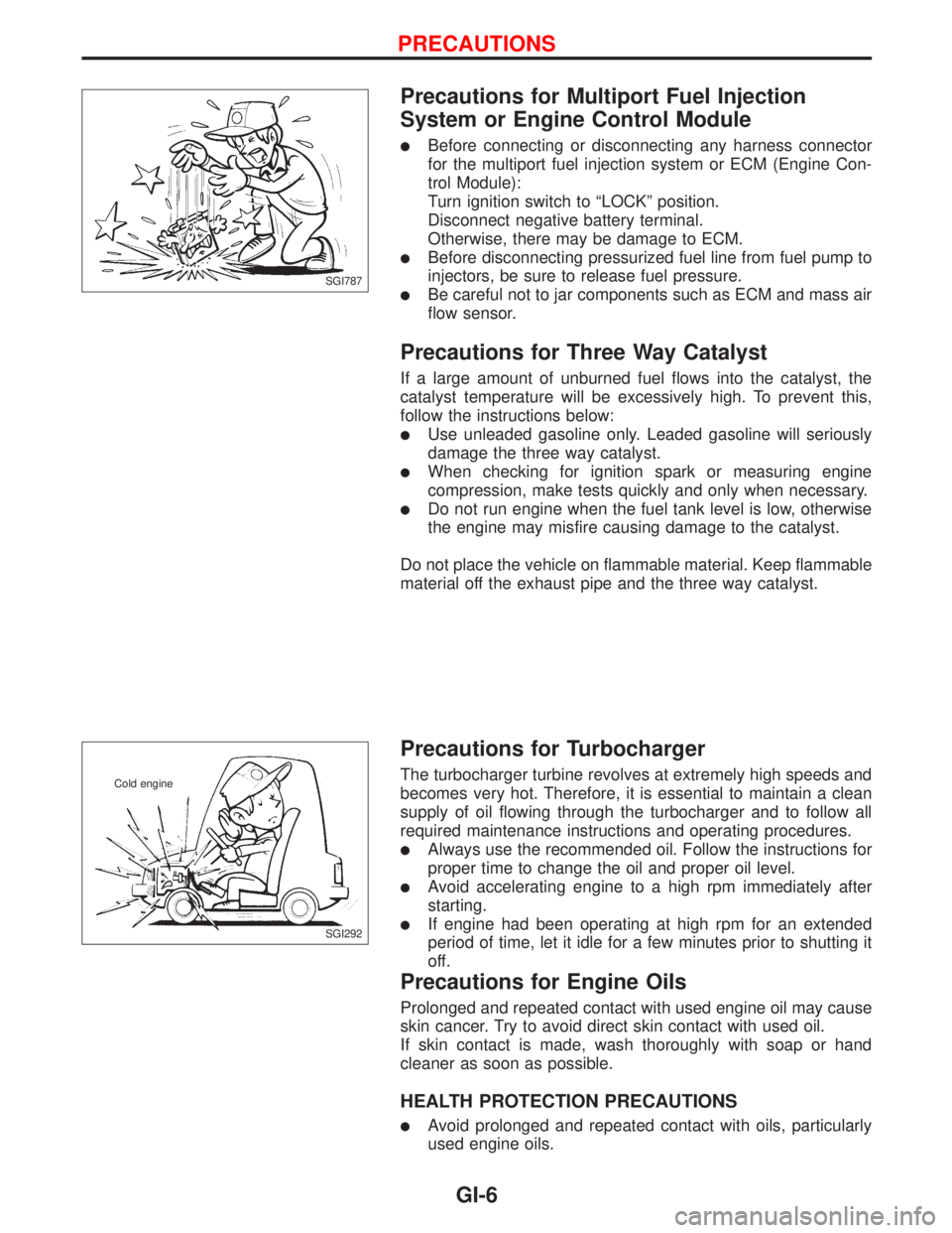
lBefore connecting or disconnecting any harness connector
for the multiport fuel injection system or ECM (Engine Con-
trol Module):
Turn ignition switch to ªLOCKº position.
Disconnect negative battery terminal.
Otherwise, there may be damage to ECM.
lBefore disconnecting pressurized fuel line from fuel pump to
injectors, be sure to release fuel pressure.
lBe careful not to jar components such as ECM and mass air
flow sensor.
Precautions for Three Way Catalyst
If a large amount of unburned fuel flows into the catalyst, the
catalyst temperature will be excessively high. To prevent this,
follow the instructions below:
lUse unleaded gasoline only. Leaded gasoline will seriously
damage the three way catalyst.
lWhen checking for ignition spark or measuring engine
compression, make tests quickly and only when necessary.
lDo not run engine when the fuel tank level is low, otherwise
the engine may misfire causing damage to the catalyst.
Do not place the vehicle on flammable material. Keep flammable
material off the exhaust pipe and the three way catalyst.
Precautions for Turbocharger
The turbocharger turbine revolves at extremely high speeds and
becomes very hot. Therefore, it is essential to maintain a clean
supply of oil flowing through the turbocharger and to follow all
required maintenance instructions and operating procedures.
lAlways use the recommended oil. Follow the instructions for
proper time to change the oil and proper oil level.
lAvoid accelerating engine to a high rpm immediately after
starting.
lIf engine had been operating at high rpm for an extended
period of time, let it idle for a few minutes prior to shutting it
off.
Precautions for Engine Oils
Prolonged and repeated contact with used engine oil may cause
skin cancer. Try to avoid direct skin contact with used oil.
If skin contact is made, wash thoroughly with soap or hand
cleaner as soon as possible.
HEALTH PROTECTION PRECAUTIONS
lAvoid prolonged and repeated contact with oils, particularly
used engine oils.
SGI787
SGI292 Cold engine
PRECAUTIONS
GI-6
Page 1815 of 2267
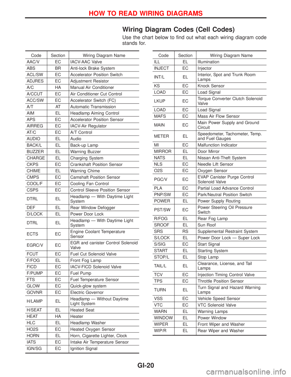
Wiring Diagram Codes (Cell Codes)
Use the chart below to find out what each wiring diagram code
stands for.
Code Section Wiring Diagram Name
AAC/V EC IACV-AAC Valve
ABS BR Anti-lock Brake System
ACL/SW EC Accelerator Position Switch
ADJRES EC Adjustment Resistor
A/C HA Manual Air Conditioner
A/CCUT EC Air Conditioner Cut Control
ACC/SW EC Accelerator Switch (FC)
A/T AT Automatic Transmission
AIM EL Headlamp Aiming Control
APS EC Accelerator Position Sensor
AIRREG EC IACV-Air Regulator
AT/C EC A/T Control
AUDIO EL Audio
BACK/L EL Back-up Lamp
BUZZER EL Warning Buzzer
CHARGE EL Charging System
CKPS EC Crankshaft Position Sensor
CHIME EL Warning Chime
CMPS EC Camshaft Position Sensor
COOL/F EC Cooling Fan Control
CSPS EC Control Sleeve Position Sensor
DTRL ELHeadlamp Ð With Daytime Light
System
DEF EL Rear Window Defogger
D/LOCK EL Power Door Lock
DTRL ELHeadlamp Ð With Daytime Light
System
ECTS ECEngine Coolant Temperature
Sensor
EGRC/V ECEGR and canister Control Solenoid
Valve
FCUT EC Fuel Cut Solenoid Valve
F/FOG EL Front Fog Lamp
FICD EC IACV-FICD Solenoid Valve
F/PUMP EC Fuel Pump
FTS EC Fuel Temperature Sensor
GLOW EC Quick-glow system
GOVNR EC Electric Governor
H/LAMP ELHeadlamp Ð Without Daytime
Light System
H/SEAT EL Heated Seat
HEAT HA Heater
HLC EL Headlamp Washer
HO2S EC Heated Oxygen Sensor
HORN EL Horn, Cigarette Lighter, Clock
IATS EC Intake Air Temperature Sensor
IGN/SG EC Ignition SignalCode Section Wiring Diagram Name
ILL EL Illumination
INJECT EC Injector
INT/L ELInterior, Spot and Trunk Room
Lamps
KS EC Knock Sensor
LOAD EC Load Signal
LKUP ECTorque Converter Clutch Solenoid
Valve
LOAD EC Load Signal
MAFS EC Mass Air Flow Sensor
MAIN ECMain Power Supply and Ground
Circuit
METER ELSpeedometer, Tachometer, Temp.
and Fuel Gauges
MI EC Malfunction Indicator
MIRROR EL Door Mirror
NATS EL Nissan Anti-Theft System
NLS EC Needle Lift Sensor
O2S EC Oxygen Sensor
PGC/V ECEVAP Canister Purge Control
Solenoid Valve
PLA EC Partial Load Advance Control
PNP/SW EC Park/Neutral Position Switch
POWER EL Power Supply Routing
PST/SW ECPower Steering Oil Pressure
Switch
R/FOG EL Rear Fog Lamp
SROOF EL Sun Roof
SRS RS Supplemental Restraint System
S/LOCK EL Power Door Lock Ð Super Lock
S/SIG EC Start Signal
START EL Starting System
STOP/L EL Stop Lamp
TAIL/L ELClearance, License, and Tail
Lamps
TCV EC Injection Timing Control Valve
TPS EC Throttle Position Sensor
TURN ELTurn Signal and Hazard Warning
Lamps
VSS EC Vehicle Speed Sensor
VTC EC VTC Solenoid Valve
WARN EL Warning Lamps
WINDOW EL Power Window
WIPER EL Front Wiper and Washer
WIP/R EL Rear Wiper and Washer
HOW TO READ WIRING DIAGRAMS
GI-20
Page 1846 of 2267
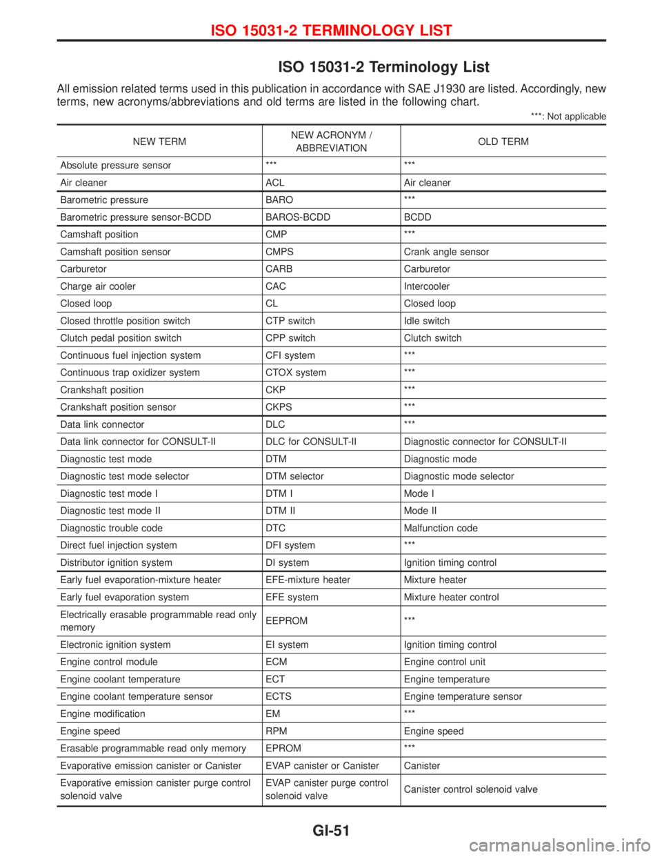
ISO 15031-2 Terminology List
All emission related terms used in this publication in accordance with SAE J1930 are listed. Accordingly, new
terms, new acronyms/abbreviations and old terms are listed in the following chart.
***: Not applicable
NEW TERMNEW ACRONYM /
ABBREVIATIONOLD TERM
Absolute pressure sensor *** ***
Air cleaner ACL Air cleaner
Barometric pressure BARO ***
Barometric pressure sensor-BCDD BAROS-BCDD BCDD
Camshaft position CMP ***
Camshaft position sensor CMPS Crank angle sensor
Carburetor CARB Carburetor
Charge air cooler CAC Intercooler
Closed loop CL Closed loop
Closed throttle position switch CTP switch Idle switch
Clutch pedal position switch CPP switch Clutch switch
Continuous fuel injection system CFI system ***
Continuous trap oxidizer system CTOX system ***
Crankshaft position CKP ***
Crankshaft position sensor CKPS ***
Data link connector DLC ***
Data link connector for CONSULT-II DLC for CONSULT-II Diagnostic connector for CONSULT-II
Diagnostic test mode DTM Diagnostic mode
Diagnostic test mode selector DTM selector Diagnostic mode selector
Diagnostic test mode I DTM I Mode I
Diagnostic test mode II DTM II Mode II
Diagnostic trouble code DTC Malfunction code
Direct fuel injection system DFI system ***
Distributor ignition system DI system Ignition timing control
Early fuel evaporation-mixture heater EFE-mixture heater Mixture heater
Early fuel evaporation system EFE system Mixture heater control
Electrically erasable programmable read only
memoryEEPROM ***
Electronic ignition system EI system Ignition timing control
Engine control module ECM Engine control unit
Engine coolant temperature ECT Engine temperature
Engine coolant temperature sensor ECTS Engine temperature sensor
Engine modification EM ***
Engine speed RPM Engine speed
Erasable programmable read only memory EPROM ***
Evaporative emission canister or Canister EVAP canister or Canister Canister
Evaporative emission canister purge control
solenoid valveEVAP canister purge control
solenoid valveCanister control solenoid valve
ISO 15031-2 TERMINOLOGY LIST
GI-51
Page 1847 of 2267
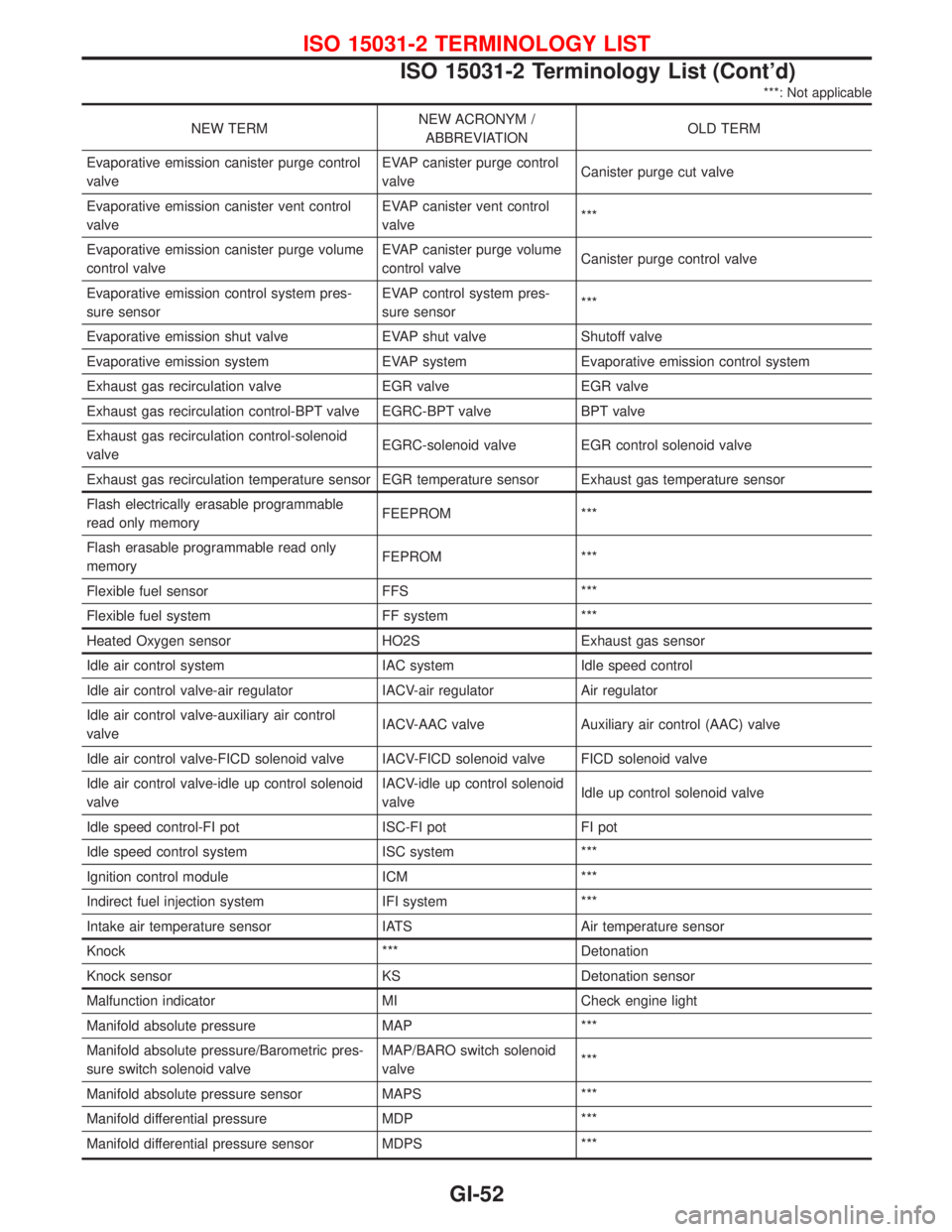
***: Not applicable
NEW TERMNEW ACRONYM /
ABBREVIATIONOLD TERM
Evaporative emission canister purge control
valveEVAP canister purge control
valveCanister purge cut valve
Evaporative emission canister vent control
valveEVAP canister vent control
valve***
Evaporative emission canister purge volume
control valveEVAP canister purge volume
control valveCanister purge control valve
Evaporative emission control system pres-
sure sensorEVAP control system pres-
sure sensor***
Evaporative emission shut valve EVAP shut valve Shutoff valve
Evaporative emission system EVAP system Evaporative emission control system
Exhaust gas recirculation valve EGR valve EGR valve
Exhaust gas recirculation control-BPT valve EGRC-BPT valve BPT valve
Exhaust gas recirculation control-solenoid
valveEGRC-solenoid valve EGR control solenoid valve
Exhaust gas recirculation temperature sensor EGR temperature sensor Exhaust gas temperature sensor
Flash electrically erasable programmable
read only memoryFEEPROM ***
Flash erasable programmable read only
memoryFEPROM ***
Flexible fuel sensor FFS ***
Flexible fuel system FF system ***
Heated Oxygen sensor HO2S Exhaust gas sensor
Idle air control system IAC system Idle speed control
Idle air control valve-air regulator IACV-air regulator Air regulator
Idle air control valve-auxiliary air control
valveIACV-AAC valve Auxiliary air control (AAC) valve
Idle air control valve-FICD solenoid valve IACV-FICD solenoid valve FICD solenoid valve
Idle air control valve-idle up control solenoid
valveIACV-idle up control solenoid
valveIdle up control solenoid valve
Idle speed control-FI pot ISC-FI pot FI pot
Idle speed control system ISC system ***
Ignition control module ICM ***
Indirect fuel injection system IFI system ***
Intake air temperature sensor IATS Air temperature sensor
Knock *** Detonation
Knock sensor KS Detonation sensor
Malfunction indicator MI Check engine light
Manifold absolute pressure MAP ***
Manifold absolute pressure/Barometric pres-
sure switch solenoid valveMAP/BARO switch solenoid
valve***
Manifold absolute pressure sensor MAPS ***
Manifold differential pressure MDP ***
Manifold differential pressure sensor MDPS ***
ISO 15031-2 TERMINOLOGY LIST
ISO 15031-2 Terminology List (Cont'd)
GI-52
Page 1970 of 2267
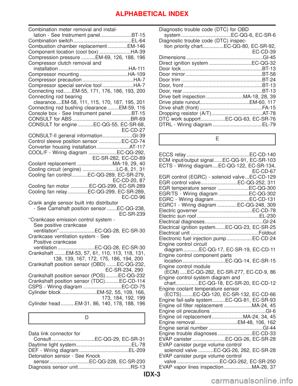
Combination meter removal and instal-
lation - See Instrument panel ......................BT-15
Combination switch .........................................EL-64
Combustion chamber replacement ..............EM-146
Component location (cool box) ......................HA-39
Compression pressure ..........EM-69, 126, 188, 196
Compressor clutch removal and
installation .................................................HA-111
Compressor mounting ..................................HA-109
Compressor precaution ....................................HA-7
Compressor special service tool ......................HA-7
Connecting rod......EM-55, 171, 176, 186, 193, 200
Connecting rod bearing
clearance....EM-58, 111, 115, 170, 187, 195, 201
Connecting rod bushing clearance ........EM-59, 116
Console box - See Instrument panel ..............BT-15
CONSULT for ABS .........................................BR-69
CONSULT for engine ...........EC-QG-55, EC-SR-68,
EC-CD-27
CONSULT-II general information .....................GI-39
Control sleeve position sensor ................EC-CD-74
Converter housing installation .......................AT-117
COOL/F - Wiring diagram ....................EC-QG-292,
EC-SR-282, EC-CD-89
Coolant replacement .........................MA-19, 29, 40
Cooling circuit (engine) ........................LC-8, 21, 31
Cooling fan control ...........EC-QG-289, EC-SR-279,
EC-CD-20, 87
Cooling fan motor .............EC-QG-299, EC-SR-289
Cooling fan relay ..............EC-QG-299, EC-SR-289,
EC-CD-96
Crank angle sensor built into distributor
- See Camshaft position sensor .......EC-QG-238,
EC-SR-239
‘‘Crankcase emission control system -
See positive crankcase
ventilation’’ .........................EC-QG-28, EC-SR-30
Crankcase ventilation system - See
Positive crankcase
ventilation ..........................EC-QG-28, EC-SR-30
Crankshaft ........EM-53, 57, 61, 110, 113, 118, 131,
138, 139, 167, 172, 175, 186, 194, 200
Crankshaft position sensor (OBD) .......EC-QG-232,
EC-SR-234, 290
Crankshaft position sensor (POS).........EC-QG-232
Crankshaft position sensor (TDC)..........EC-CD-114
CSPS - Wiring diagram ...........................EC-CD-75
Cylinder block .........................EM-52, 55, 109, 166,
173, 184, 192, 199
Cylinder head ..........EM-31, 86, 140, 178, 188, 196
D
Data link connector for
Consult ..............................EC-QG-29, EC-SR-31
Daytime light system.......................................EL-78
DEF - Wiring diagram ...................................EL-209
Detonation sensor - See Knock
sensor ............................EC-QG-228, EC-SR-230
Diagnosis sensor unit .....................................RS-13Diagnostic trouble code (DTC) for OBD
system ...................................EC-QG-6, EC-SR-6
Diagnostic trouble code (DTC) inspec-
tion priority chart...............EC-QG-80, EC-SR-92,
EC-CD-39
Dimensions ......................................................GI-45
Direct ignition system ..............................EC-QG-32
Door lock .........................................................BT-13
Door mirror ......................................................BT-58
Door trim .........................................................BT-24
Door, front .......................................................BT-13
Door, rear ........................................................BT-13
Drive belt inspection ..........................MA-18, 28, 39
Drive plate runout...................................EM-60, 117
Drive shaft (front) ............................................FA-15
Dropping resistor (A/T) ....................................AT-78
DTC work support .................EC-QG-63, EC-SR-76
DTRL - Wiring diagram ...................................EL-79
E
ECCS relay ............................................EC-CD-140
ECM input/output signal......EC-QG-91, EC-SR-103
ECTS - Wiring diagram ....EC-QG-122, EC-SR-134,
EC-CD-67
EGR control (EGRC) - solenoid valve ...EC-CD-129
EGR control valve..........................EC-QG-252, 311
EGR temperature sensor ......................EC-QG-300
EGR/TS - Wiring diagram .....................EC-QG-302
EGRC - Wiring diagram .........................EC-CD-131
EGRC1 - Wiring diagram ..............EC-QG-248, 309
Electric governer ......................................EC-CD-78
Electric sun roof ............................................EL-230
Electrical diagnoses.........................................GI-24
Electrical ignition system.......EC-QG-23, EC-SR-25
Electrical unit ................................................Foldout
Electronic fuel injection pump ..................EC-CD-24
Engine control circuit
diagram ...........EC-QG-17, EC-SR-19, EC-CD-11
Engine control component parts
location ..............................EC-QG-14, EC-SR-15
Engine control module
(ECM) .....EC-QG-282, EC-SR-277, EC-CD-9, 86
Engine control system diagram and
chart ................EC-QG-18, EC-SR-20, EC-CD-12
Engine coolant temperature sensor
(ECTS) ........EC-QG-120, EC-SR-132, EC-CD-66
Engine fail-safe system .........EC-QG-81, EC-SR-93
Engine oil filter replacement ....................MA-24, 45
Engine oil precautions .......................................GI-6
Engine oil replacement ......................MA-24, 34, 45
Engine removal..............................EM-48, 106, 162
Engine serial number ......................................GI-44
Engine trouble diagnoses ........................EC-CD-33
EVAP canister .......................EC-QG-26, EC-SR-28
EVAP canister purge volume control
solenoid valve ...........EC-QG-26, 262, EC-SR-28
EVAP canister purge volume control
valve ..............................EC-QG-262, EC-SR-250
EVAP vapor lines inspection....................MA-26, 37
ALPHABETICAL INDEX
IDX-3