Page 1243 of 2267
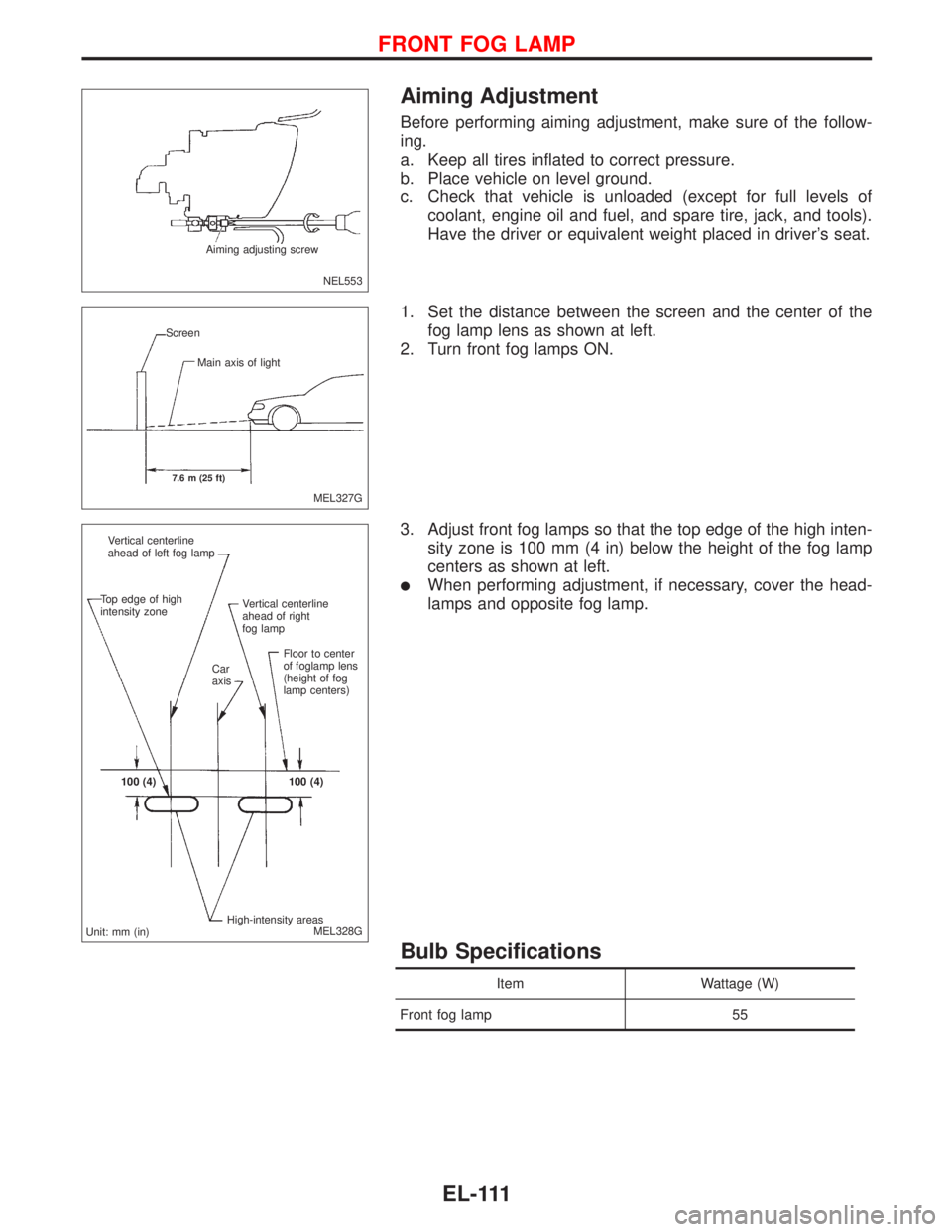
Aiming Adjustment
Before performing aiming adjustment, make sure of the follow-
ing.
a. Keep all tires inflated to correct pressure.
b. Place vehicle on level ground.
c. Check that vehicle is unloaded (except for full levels of
coolant, engine oil and fuel, and spare tire, jack, and tools).
Have the driver or equivalent weight placed in driver’s seat.
1. Set the distance between the screen and the center of the
fog lamp lens as shown at left.
2. Turn front fog lamps ON.
3. Adjust front fog lamps so that the top edge of the high inten-
sity zone is 100 mm (4 in) below the height of the fog lamp
centers as shown at left.
�When performing adjustment, if necessary, cover the head-
lamps and opposite fog lamp.
Bulb Specifications
Item Wattage (W)
Front fog lamp 55
NEL553 Aiming adjusting screw
MEL327G
7.6 m (25 ft)
Screen
Main axis of light
MEL328G Vertical centerline
ahead of left fog lamp
Car
axis Top edge of high
intensity zoneVertical centerline
ahead of right
fog lamp
Floor to center
of foglamp lens
(height of fog
lamp centers)
.100 (4).100 (4)
High-intensity areas
Unit: mm (in)
FRONT FOG LAMP
EL-111
Page 1311 of 2267
Electrical Components Inspection
FUEL WARNING LAMP OPERATION CHECK
1. Turn ignition switch“OFF”.
2. Disconnect fuel level sensor unit harness connector
B31.
3. Connect a resistor (172 - 180Ω) between fuel tank gauge unit
harness connector terminals
�1and�3.
4. Turn ignition switch“ON”.
The fuel warning lamp should come on.
OIL PRESSURE SWITCH CHECK
Oil pressure
kPa (kg/cm2, psi)Continuity
Engine startMore than 10 - 20
(0.1-0.2,1-3)NO
Engine stopLess than 10 - 20
(0.1-0.2,1-3)YES
Check the continuity between the terminals of oil pressure switch
and body ground.
YEL455B Fuel level sensor unit connector
172 - 180Ωresistor
MEL425F Ohmmeter
WARNING LAMPS
EL-179
Page 1556 of 2267
1. Warm up engine.
2. Turn ignition switch OFF.
3. Release fuel pressure.
Refer to ªReleasing Fuel Pressureº in EC section.
4. Remove ignition coils.
5. Remove spark plugs.
IClean area around plug with compressed air before removing
the spark plug.
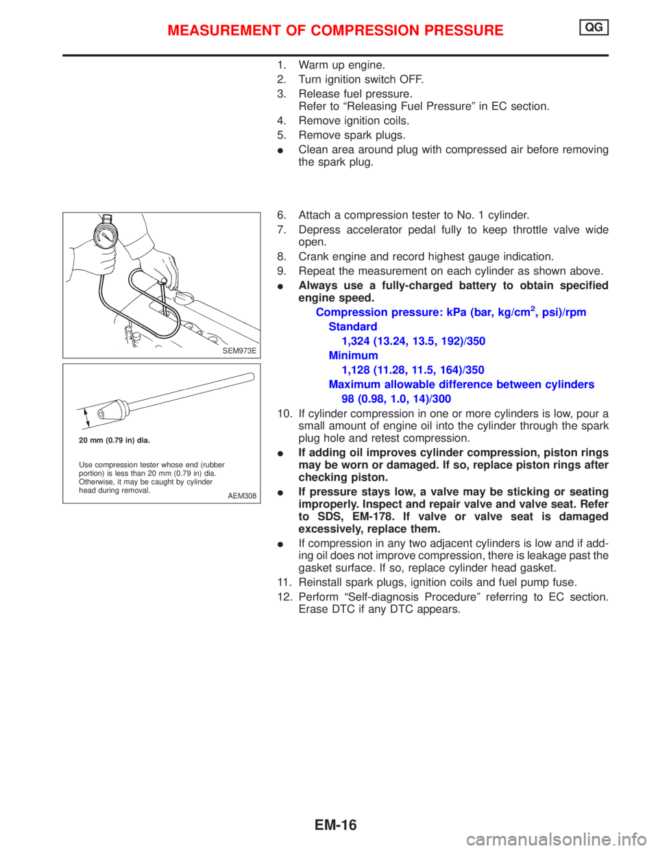
6. Attach a compression tester to No. 1 cylinder.
7. Depress accelerator pedal fully to keep throttle valve wide
open.
8. Crank engine and record highest gauge indication.
9. Repeat the measurement on each cylinder as shown above.
IAlways use a fully-charged battery to obtain specified
engine speed.
Compression pressure: kPa (bar, kg/cm
2, psi)/rpm
Standard
1,324 (13.24, 13.5, 192)/350
Minimum
1,128 (11.28, 11.5, 164)/350
Maximum allowable difference between cylinders
98 (0.98, 1.0, 14)/300
10. If cylinder compression in one or more cylinders is low, pour a
small amount of engine oil into the cylinder through the spark
plug hole and retest compression.
IIf adding oil improves cylinder compression, piston rings
may be worn or damaged. If so, replace piston rings after
checking piston.
IIf pressure stays low, a valve may be sticking or seating
improperly. Inspect and repair valve and valve seat. Refer
to SDS, EM-178. If valve or valve seat is damaged
excessively, replace them.
IIf compression in any two adjacent cylinders is low and if add-
ing oil does not improve compression, there is leakage past the
gasket surface. If so, replace cylinder head gasket.
11. Reinstall spark plugs, ignition coils and fuel pump fuse.
12. Perform ªSelf-diagnosis Procedureº referring to EC section.
Erase DTC if any DTC appears.
SEM973E
AEM308 20 mm (0.79 in) dia.
Use compression tester whose end (rubber
portion) is less than 20 mm (0.79 in) dia.
Otherwise, it may be caught by cylinder
head during removal.
MEASUREMENT OF COMPRESSION PRESSUREQG
EM-16
Page 1560 of 2267
CAUTION:
IAfter removing timing chain, do not turn crankshaft and
camshaft separately, or valves will strike piston heads.
IWhen installing chain tensioner, oil seals, or other sliding
parts, lubricate contacting surfaces with new engine oil.
IApply new engine oil to bolt threads and seat surfaces
when installing camshaft sprocket and crankshaft pulley.
IWhen removing oil pump assembly, remove camshaft
position sensor (PHASE), then remove timing chain from
engine.
IBe careful not to damage sensor edges.
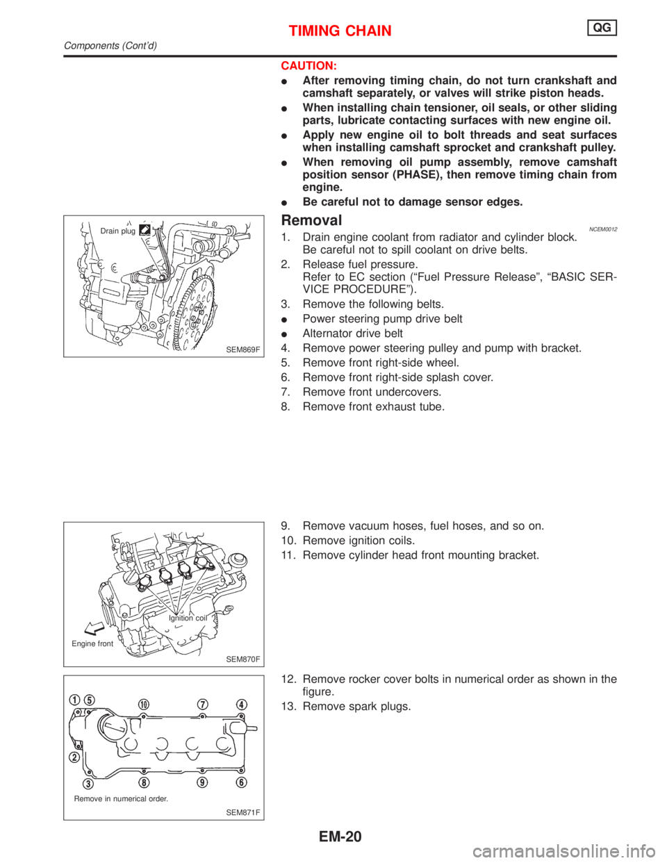
RemovalNCEM00121. Drain engine coolant from radiator and cylinder block.
Be careful not to spill coolant on drive belts.
2. Release fuel pressure.
Refer to EC section (ªFuel Pressure Releaseº, ªBASIC SER-
VICE PROCEDUREº).
3. Remove the following belts.
IPower steering pump drive belt
IAlternator drive belt
4. Remove power steering pulley and pump with bracket.
5. Remove front right-side wheel.
6. Remove front right-side splash cover.
7. Remove front undercovers.
8. Remove front exhaust tube.
9. Remove vacuum hoses, fuel hoses, and so on.
10. Remove ignition coils.
11. Remove cylinder head front mounting bracket.
12. Remove rocker cover bolts in numerical order as shown in the
figure.
13. Remove spark plugs.
SEM869F Drain plug
SEM870F Ignition coil
Engine front
SEM871F Remove in numerical order.
TIMING CHAINQG
Components (Cont'd)
EM-20
Page 1572 of 2267
CAUTION:
IWhen installing camshaft and oil seal, lubricate contacting
surfaces with new engine oil.
IWhen tightening cylinder head bolts, camshaft sprocket
bolts and camshaft bracket bolts, lubricate bolt threads
and seat surfaces with new engine oil.
IAttach tags to valve lifters so as not to mix them up.
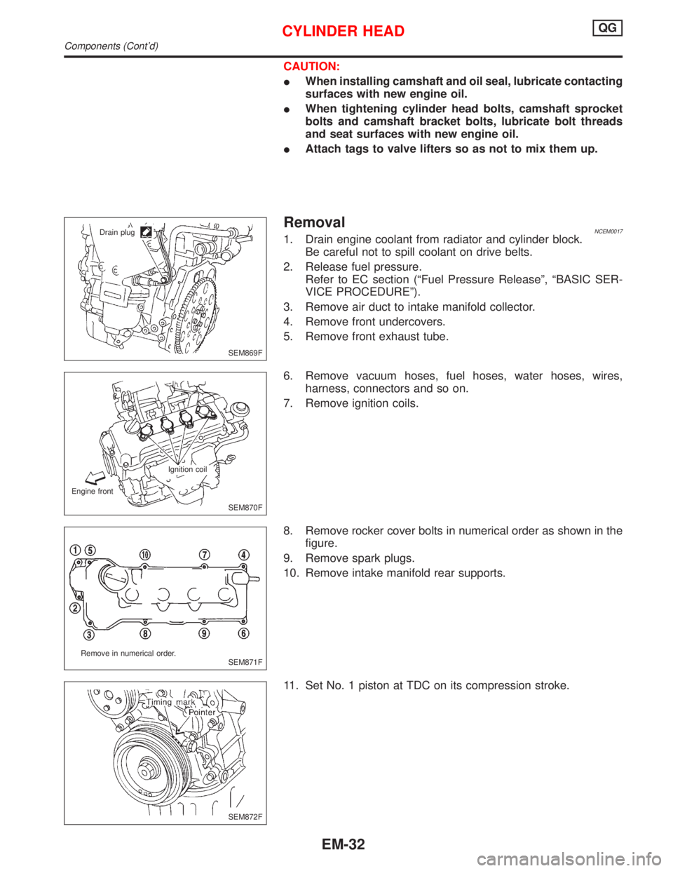
RemovalNCEM00171. Drain engine coolant from radiator and cylinder block.
Be careful not to spill coolant on drive belts.
2. Release fuel pressure.
Refer to EC section (ªFuel Pressure Releaseº, ªBASIC SER-
VICE PROCEDUREº).
3. Remove air duct to intake manifold collector.
4. Remove front undercovers.
5. Remove front exhaust tube.
6. Remove vacuum hoses, fuel hoses, water hoses, wires,
harness, connectors and so on.
7. Remove ignition coils.
8. Remove rocker cover bolts in numerical order as shown in the
figure.
9. Remove spark plugs.
10. Remove intake manifold rear supports.
11. Set No. 1 piston at TDC on its compression stroke.
SEM869F Drain plug
SEM870F Ignition coil
Engine front
SEM871F Remove in numerical order.
SEM872F
CYLINDER HEADQG
Components (Cont'd)
EM-32
Page 1589 of 2267
WARNING:
IPosition vehicle on a flat and solid surface.
IPlace chocks at front and back of rear wheels.
IDo not remove engine until exhaust system has com-
pletely cooled off, otherwise, you may burn yourself
and/or fire may break out in fuel line.
IBefore disconnecting fuel hose, release pressure.
Refer to EC section (ªFuel Pressure Releaseº, ªBASIC
SERVICE PROCEDUREº).
IBe sure to lift engine and transaxle in a safe manner.
IFor engines not equipped with engine slingers, attach
proper slingers and bolts described in PARTS CATALOG.
CAUTION:
IWhen lifting engine, be sure to clear surrounding parts.
Use special care near accelerator wire casing, brake lines
and brake master cylinder.
IWhen lifting the engine, always use engine slingers in a
safe manner.
IWhen removing drive shaft, be careful not to damage
grease seal of transaxle.
IBefore separating engine and transaxle, remove crank-
shaft position sensor (POS) from the cylinder block
assembly.
IAlways be extra careful not to damage edge of crankshaft
position sensor (POS), or signal plate teeth.
Engine cannot be removed separately from transaxle. Remove
engine with transaxle as an assembly.
REMOVALNCEM0022S011. Drain coolant from radiator and cylinder block. Refer to (LC)
section (ªChanging Engine Coolantº, ªENGINE MAINTE-
NANCEº).
2. Drain engine oil.
3. Remove battery.
4. Remove coolant reservoir tank and bracket.
5. Remove drive belts.
6. Remove generator and air conditioner compressor from
engine.
7. Remove power steering oil pump from engine and position
aside.
Power steering oil pump does not need to be disconnected
from power steering tubes.
ENGINE REMOVALQG
Removal and Installation (Cont'd)
EM-49
Page 1609 of 2267
Measurement of Compression Pressure
1. Warm up engine.
2. Turn ignition switch off.
3. Release fuel pressure.
Refer to ªReleasing Fuel Pressureº in EC-section.
4. Remove all spark plugs.
5. Disconnect distributor center cable.
6. Attach a compression tester to No. 1 cylinder.
7. Depress accelerator pedal fully to keep throttle valve wide
open.
8. Crank engine and record highest gauge indication.
9. Repeat the measurement for each cylinder.
IAlways use a fully-charged battery to obtain specified
engine revolution.
Compression pressure:
kPa (bar, kg/cm2, psi)/300 rpm
Standard 1,275 (12.75, 13.0, 185)
Minimum 1,079 (10.79, 11.0, 156)
Difference limit between cylinders 98 (0.98, 1.0, 14)
10. If cylinder compression in one or more cylinders is low:
A: pour a small amount of engine oil into cylinders through
spark plug holes.
B: retest compression.
IIf adding oil helps compression, piston rings may be worn
or damaged. If so, replace piston rings after checking pis-
ton condition.
IIf pressure stays low, a valve may be sticking or seating
badly. Inspect and repair valve and valve seat. (Refer to
SDS). If valve or valve seat is damaged excessively,
replace them.
IIf compression stays low in two cylinders that are next to
each other:
A. The cylinder head gasket may be leaking, or
B. Both cylinders may have valve component damage.
Inspect and repair as necessary.
SEM968C
NEM118 20 mm (0.79 in) dia
Compression tester rubber adaptor
diameter should be less than 20 mm (0.79 in)
to prevent fouling with cylinder head.
COMPRESSION PRESSURESR20DE
Measurement of Compression Pressure
EM-69
Page 1627 of 2267
RemovalNLEM01311. Release fuel pressure.
Refer to EC-SR-31, ªFuel Pressure Releaseº.
2. Remove engine under covers.
3. Remove front RH wheel and engine side cover.
4. Drain coolant by removing cylinder block drain plug and radia-
tor drain cock. Refer to MA-29, ªChanging Engine Coolantº.
5. Remove radiator.
6. Remove air duct to intake manifold.
7. Disconnect the following parts:
IVacuum hoses
IFuel hoses
IWires
IHarness
IConnectors
IFront exhaust tube
8. Remove all spark plugs.
9. Remove rocker cover bolts in numerical order.
10. Remove rocker cover.
11. Remove intake manifold supports.
12. Remove water pipe assembly.
SEM029G Engine
front
Loosen in numerical order.Rocker cover
SEM030G Intake manifold
supports
SEM065GIntake
manifold
CYLINDER HEADSR20DE
Removal
EM-87