1999 NISSAN PRIMERA fuel pressure
[x] Cancel search: fuel pressurePage 466 of 2267
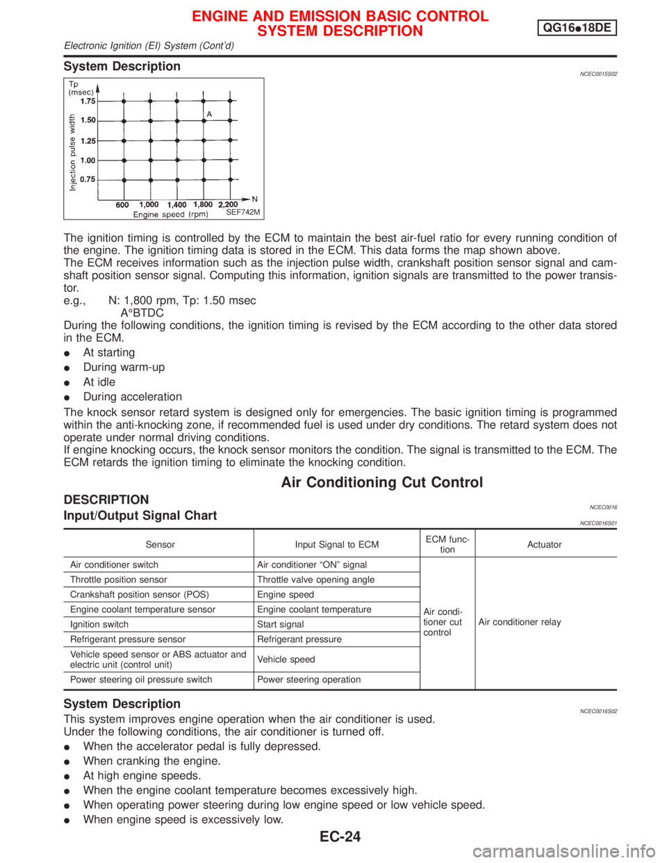
System DescriptionNCEC0015S02
The ignition timing is controlled by the ECM to maintain the best air-fuel ratio for every running condition of
the engine. The ignition timing data is stored in the ECM. This data forms the map shown above.
The ECM receives information such as the injection pulse width, crankshaft position sensor signal and cam-
shaft position sensor signal. Computing this information, ignition signals are transmitted to the power transis-
tor.
e.g., N: 1,800 rpm, Tp: 1.50 msec
AÉBTDC
During the following conditions, the ignition timing is revised by the ECM according to the other data stored
in the ECM.
IAt starting
IDuring warm-up
IAt idle
IDuring acceleration
The knock sensor retard system is designed only for emergencies. The basic ignition timing is programmed
within the anti-knocking zone, if recommended fuel is used under dry conditions. The retard system does not
operate under normal driving conditions.
If engine knocking occurs, the knock sensor monitors the condition. The signal is transmitted to the ECM. The
ECM retards the ignition timing to eliminate the knocking condition.
Air Conditioning Cut Control
DESCRIPTIONNCEC0016Input/Output Signal ChartNCEC0016S01
Sensor Input Signal to ECMECM func-
tionActuator
Air conditioner switch Air conditioner ªONº signal
Air condi-
tioner cut
controlAir conditioner relay Throttle position sensor Throttle valve opening angle
Crankshaft position sensor (POS) Engine speed
Engine coolant temperature sensor Engine coolant temperature
Ignition switch Start signal
Refrigerant pressure sensor Refrigerant pressure
Vehicle speed sensor or ABS actuator and
electric unit (control unit)Vehicle speed
Power steering oil pressure switch Power steering operation
System DescriptionNCEC0016S02This system improves engine operation when the air conditioner is used.
Under the following conditions, the air conditioner is turned off.
IWhen the accelerator pedal is fully depressed.
IWhen cranking the engine.
IAt high engine speeds.
IWhen the engine coolant temperature becomes excessively high.
IWhen operating power steering during low engine speed or low vehicle speed.
IWhen engine speed is excessively low.
SEF742M
ENGINE AND EMISSION BASIC CONTROL
SYSTEM DESCRIPTIONQG16I18DE
Electronic Ignition (EI) System (Cont'd)
EC-24
Page 468 of 2267
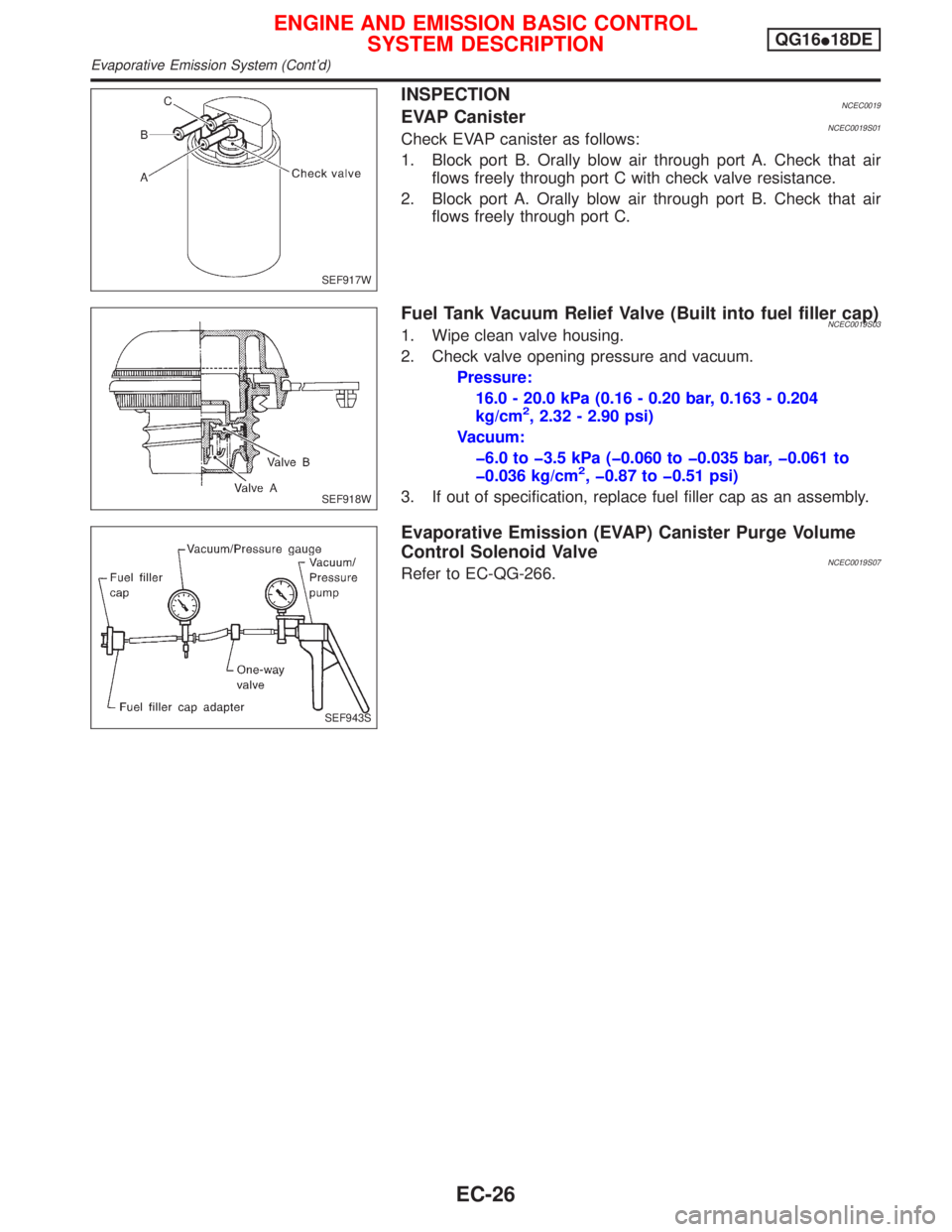
INSPECTIONNCEC0019EVAP CanisterNCEC0019S01Check EVAP canister as follows:
1. Block port B. Orally blow air through port A. Check that air
flows freely through port C with check valve resistance.
2. Block port A. Orally blow air through port B. Check that air
flows freely through port C.
Fuel Tank Vacuum Relief Valve (Built into fuel filler cap)NCEC0019S031. Wipe clean valve housing.
2. Check valve opening pressure and vacuum.
Pressure:
16.0 - 20.0 kPa (0.16 - 0.20 bar, 0.163 - 0.204
kg/cm
2, 2.32 - 2.90 psi)
Vacuum:
þ6.0 to þ3.5 kPa (þ0.060 to þ0.035 bar, þ0.061 to
þ0.036 kg/cm
2, þ0.87 to þ0.51 psi)
3. If out of specification, replace fuel filler cap as an assembly.
Evaporative Emission (EVAP) Canister Purge Volume
Control Solenoid Valve
NCEC0019S07Refer to EC-QG-266.
SEF917W
SEF918W
SEF943S
ENGINE AND EMISSION BASIC CONTROL
SYSTEM DESCRIPTIONQG16I18DE
Evaporative Emission System (Cont'd)
EC-26
Page 471 of 2267
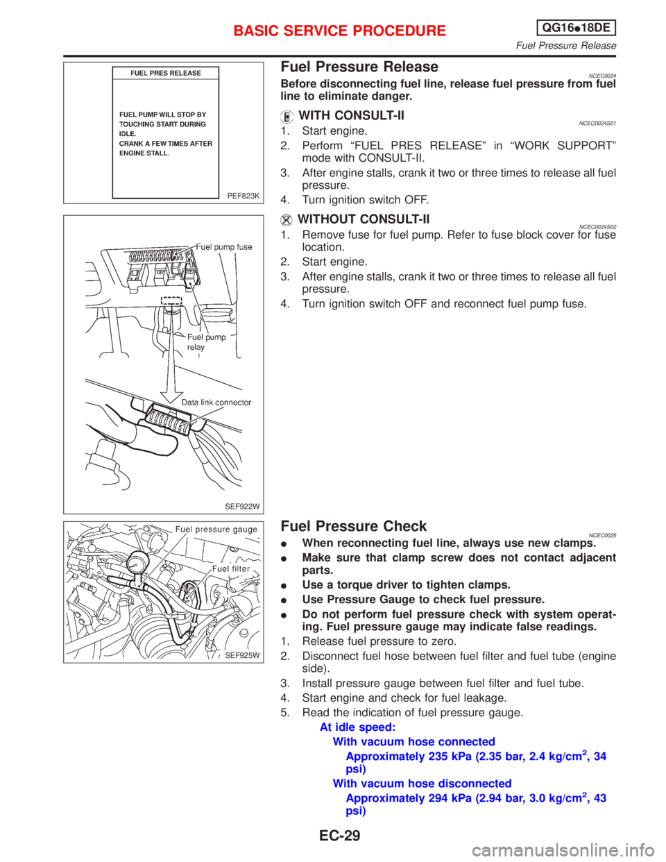
Fuel Pressure ReleaseNCEC0024Before disconnecting fuel line, release fuel pressure from fuel
line to eliminate danger.
WITH CONSULT-IINCEC0024S011. Start engine.
2. Perform ªFUEL PRES RELEASEº in ªWORK SUPPORTº
mode with CONSULT-II.
3. After engine stalls, crank it two or three times to release all fuel
pressure.
4. Turn ignition switch OFF.
WITHOUT CONSULT-IINCEC0024S021. Remove fuse for fuel pump. Refer to fuse block cover for fuse
location.
2. Start engine.
3. After engine stalls, crank it two or three times to release all fuel
pressure.
4. Turn ignition switch OFF and reconnect fuel pump fuse.
Fuel Pressure CheckNCEC0025IWhen reconnecting fuel line, always use new clamps.
IMake sure that clamp screw does not contact adjacent
parts.
IUse a torque driver to tighten clamps.
IUse Pressure Gauge to check fuel pressure.
IDo not perform fuel pressure check with system operat-
ing. Fuel pressure gauge may indicate false readings.
1. Release fuel pressure to zero.
2. Disconnect fuel hose between fuel filter and fuel tube (engine
side).
3. Install pressure gauge between fuel filter and fuel tube.
4. Start engine and check for fuel leakage.
5. Read the indication of fuel pressure gauge.
At idle speed:
With vacuum hose connected
Approximately 235 kPa (2.35 bar, 2.4 kg/cm
2,34
psi)
With vacuum hose disconnected
Approximately 294 kPa (2.94 bar, 3.0 kg/cm
2,43
psi)
PEF823K
SEF922W
SEF925W
BASIC SERVICE PROCEDUREQG16I18DE
Fuel Pressure Release
EC-29
Page 472 of 2267
If results are unsatisfactory, perform Fuel Pressure Regulator
Check, EC-QG-30.
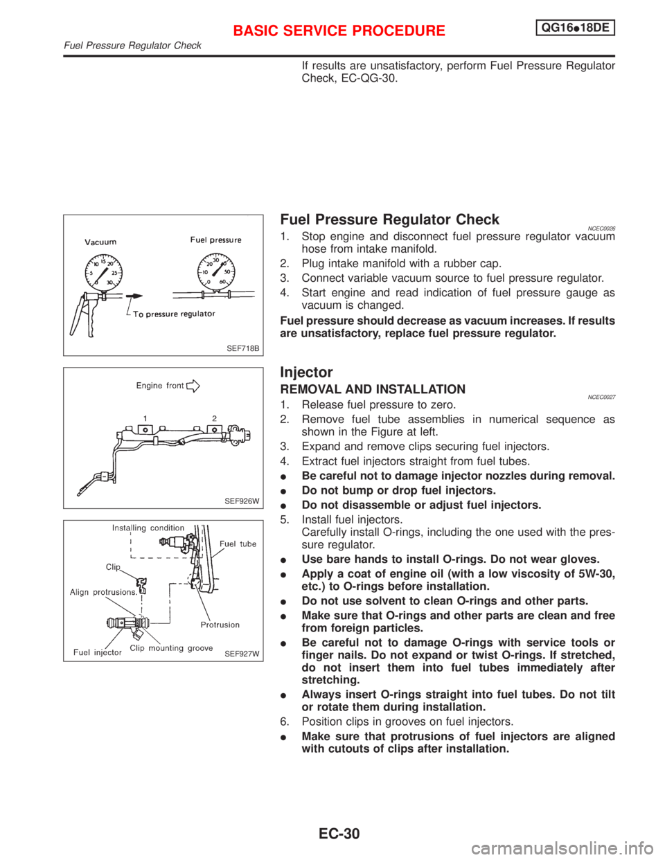
Fuel Pressure Regulator CheckNCEC00261. Stop engine and disconnect fuel pressure regulator vacuum
hose from intake manifold.
2. Plug intake manifold with a rubber cap.
3. Connect variable vacuum source to fuel pressure regulator.
4. Start engine and read indication of fuel pressure gauge as
vacuum is changed.
Fuel pressure should decrease as vacuum increases. If results
are unsatisfactory, replace fuel pressure regulator.
Injector
REMOVAL AND INSTALLATIONNCEC00271. Release fuel pressure to zero.
2. Remove fuel tube assemblies in numerical sequence as
shown in the Figure at left.
3. Expand and remove clips securing fuel injectors.
4. Extract fuel injectors straight from fuel tubes.
IBe careful not to damage injector nozzles during removal.
IDo not bump or drop fuel injectors.
IDo not disassemble or adjust fuel injectors.
5. Install fuel injectors.
Carefully install O-rings, including the one used with the pres-
sure regulator.
IUse bare hands to install O-rings. Do not wear gloves.
IApply a coat of engine oil (with a low viscosity of 5W-30,
etc.) to O-rings before installation.
IDo not use solvent to clean O-rings and other parts.
IMake sure that O-rings and other parts are clean and free
from foreign particles.
IBe careful not to damage O-rings with service tools or
finger nails. Do not expand or twist O-rings. If stretched,
do not insert them into fuel tubes immediately after
stretching.
IAlways insert O-rings straight into fuel tubes. Do not tilt
or rotate them during installation.
6. Position clips in grooves on fuel injectors.
IMake sure that protrusions of fuel injectors are aligned
with cutouts of clips after installation.
SEF718B
SEF926W
SEF927W
BASIC SERVICE PROCEDUREQG16I18DE
Fuel Pressure Regulator Check
EC-30
Page 480 of 2267
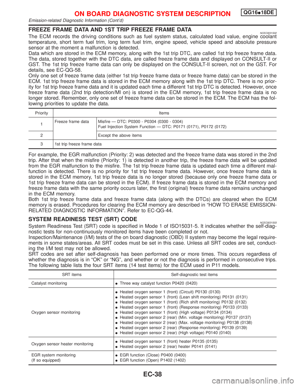
FREEZE FRAME DATA AND 1ST TRIP FREEZE FRAME DATANCEC0031S02The ECM records the driving conditions such as fuel system status, calculated load value, engine coolant
temperature, short term fuel trim, long term fuel trim, engine speed, vehicle speed and absolute pressure
sensor at the moment a malfunction is detected.
Data which are stored in the ECM memory, along with the 1st trip DTC, are called 1st trip freeze frame data.
The data, stored together with the DTC data, are called freeze frame data and displayed on CONSULT-II or
GST. The 1st trip freeze frame data can only be displayed on the CONSULT-II screen, not on the GST. For
details, see EC-QG-58.
Only one set of freeze frame data (either 1st trip freeze frame data or freeze frame data) can be stored in the
ECM. 1st trip freeze frame data is stored in the ECM memory along with the 1st trip DTC. There is no prior-
ity for 1st trip freeze frame data and it is updated each time a different 1st trip DTC is detected. However, once
freeze frame data (2nd trip detection/MI on) is stored in the ECM memory, 1st trip freeze frame data is no
longer stored. Remember, only one set of freeze frame data can be stored in the ECM. The ECM has the fol-
lowing priorities to update the data.
Priority Items
1Freeze frame data Misfire Ð DTC: P0300 - P0304 (0300 - 0304)
Fuel Injection System Function Ð DTC: P0171 (0171), P0172 (0172)
2 Except the above items
3 1st trip freeze frame data
For example, the EGR malfunction (Priority: 2) was detected and the freeze frame data was stored in the 2nd
trip. After that when the misfire (Priority: 1) is detected in another trip, the freeze frame data will be updated
from the EGR malfunction to the misfire. The 1st trip freeze frame data is updated each time a different mal-
function is detected. There is no priority for 1st trip freeze frame data. However, once freeze frame data is
stored in the ECM memory, 1st trip freeze data is no longer stored (because only one freeze frame data or
1st trip freeze frame data can be stored in the ECM). If freeze frame data is stored in the ECM memory and
freeze frame data with the same priority occurs later, the first (original) freeze frame data remains unchanged
in the ECM memory.
Both 1st trip freeze frame data and freeze frame data (along with the DTCs) are cleared when the ECM
memory is erased. Procedures for clearing the ECM memory are described in ªHOW TO ERASE EMISSION-
RELATED DIAGNOSTIC INFORMATIONº. Refer to EC-QG-44.
SYSTEM READINESS TEST (SRT) CODENCEC0031S03System Readiness Test (SRT) code is specified in Mode 1 of ISO15031-5. It indicates whether the self-diag-
nostic tests for non-continuously monitored items have been completed or not.
Inspection/Maintenance (I/M) tests of the on board diagnostic (OBD) II system may become the legal require-
ments in some states/areas. All SRT codes must be set in this case. Unless all SRT codes are set, conduct-
ing the I/M test may not be allowed.
SRT codes are set after self-diagnosis has been performed one or more times. This occurs regardless of
whether the diagnosis is in ªOKº or ªNGº, and whether or not the diagnosis is performed in consecutive trips.
The following table lists the four SRT items (14 test items) for the ECM used in P11 models.
SRT items Self-diagnostic test items
Catalyst monitoringIThree way catalyst function P0420 (0420)
Oxygen sensor monitoringIHeated oxygen sensor 1 (front) (Circuit) P0130 (0130)
IHeated oxygen sensor 1 (front) (Lean shift monitoring) P0131 (0131)
IHeated oxygen sensor 1 (front) (Rich shift monitoring) P0132 (0132)
IHeated oxygen sensor 1 (front) (Response monitoring) P0133 (0133)
IHeated oxygen sensor 1 (front) (High voltage) P0134 (0134)
IHeated oxygen sensor 2 (rear) (Min. voltage monitoring) P0137 (0137)
IHeated oxygen sensor 2 (rear) (Max. voltage monitoring) P0138 (0138)
IHeated oxygen sensor 2 (rear) (Response monitoring) P0139 (0139)
IHeated oxygen sensor 2 (rear) (High voltage) P0140 (0140)
Oxygen sensor heater monitoringIHeated oxygen sensor 1 (front) heater P0135 (0135)
IHeated oxygen sensor 2 (rear) heater P0141 (0141)
EGR system monitoring
(If so equipped)IEGR function (Close) P0400 (0400)
IEGR function (Open) P1402 (1402)
ON BOARD DIAGNOSTIC SYSTEM DESCRIPTIONQG16I18DE
Emission-related Diagnostic Information (Cont'd)
EC-38
Page 500 of 2267
4) 1st trip freeze frame data
5) System readiness test (SRT) codes
6) Test values
7) Distance traveled while MI is activated.
8) Others
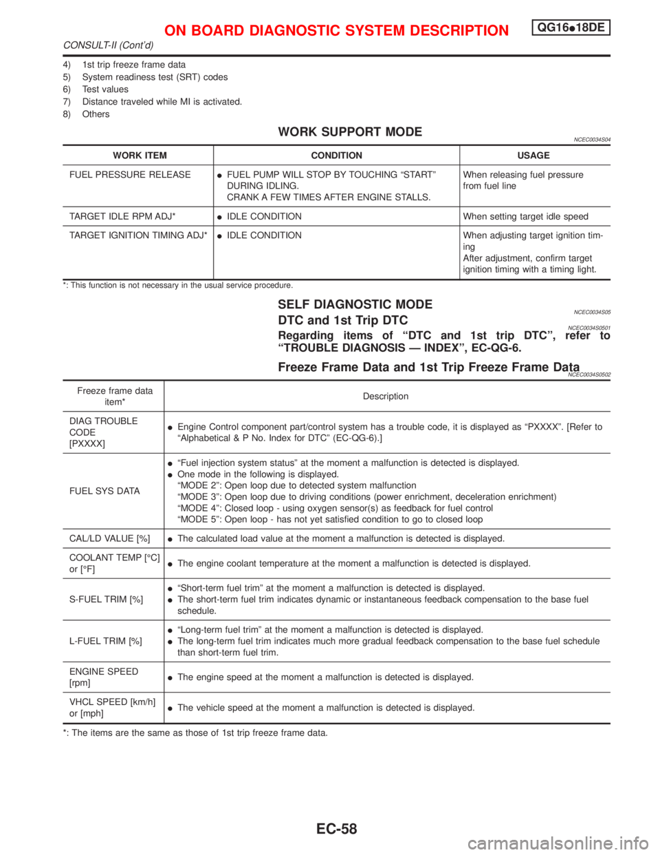
WORK SUPPORT MODENCEC0034S04
WORK ITEM CONDITION USAGE
FUEL PRESSURE RELEASEIFUEL PUMP WILL STOP BY TOUCHING ªSTARTº
DURING IDLING.
CRANK A FEW TIMES AFTER ENGINE STALLS.When releasing fuel pressure
from fuel line
TARGET IDLE RPM ADJ*IIDLE CONDITION When setting target idle speed
TARGET IGNITION TIMING ADJ*IIDLE CONDITION When adjusting target ignition tim-
ing
After adjustment, confirm target
ignition timing with a timing light.
*: This function is not necessary in the usual service procedure.
SELF DIAGNOSTIC MODENCEC0034S05DTC and 1st Trip DTCNCEC0034S0501Regarding items of ªDTC and 1st trip DTCº, refer to
ªTROUBLE DIAGNOSIS Ð INDEXº, EC-QG-6.
Freeze Frame Data and 1st Trip Freeze Frame DataNCEC0034S0502
Freeze frame data
item*Description
DIAG TROUBLE
CODE
[PXXXX]IEngine Control component part/control system has a trouble code, it is displayed as ªPXXXXº. [Refer to
ªAlphabetical & P No. Index for DTCº (EC-QG-6).]
FUEL SYS DATAIªFuel injection system statusº at the moment a malfunction is detected is displayed.
IOne mode in the following is displayed.
ªMODE 2º: Open loop due to detected system malfunction
ªMODE 3º: Open loop due to driving conditions (power enrichment, deceleration enrichment)
ªMODE 4º: Closed loop - using oxygen sensor(s) as feedback for fuel control
ªMODE 5º: Open loop - has not yet satisfied condition to go to closed loop
CAL/LD VALUE [%]IThe calculated load value at the moment a malfunction is detected is displayed.
COOLANT TEMP [ÉC]
or [ÉF]IThe engine coolant temperature at the moment a malfunction is detected is displayed.
S-FUEL TRIM [%]IªShort-term fuel trimº at the moment a malfunction is detected is displayed.
IThe short-term fuel trim indicates dynamic or instantaneous feedback compensation to the base fuel
schedule.
L-FUEL TRIM [%]IªLong-term fuel trimº at the moment a malfunction is detected is displayed.
IThe long-term fuel trim indicates much more gradual feedback compensation to the base fuel schedule
than short-term fuel trim.
ENGINE SPEED
[rpm]IThe engine speed at the moment a malfunction is detected is displayed.
VHCL SPEED [km/h]
or [mph]IThe vehicle speed at the moment a malfunction is detected is displayed.
*: The items are the same as those of 1st trip freeze frame data.
ON BOARD DIAGNOSTIC SYSTEM DESCRIPTIONQG16I18DE
CONSULT-II (Cont'd)
EC-58
Page 502 of 2267
![NISSAN PRIMERA 1999 Electronic Repair Manual Monitored item [Unit]ECM
input
signalsMain
signalsDescription Remarks
AIR COND SIG
[ON/OFF]qqIIndicates [ON/OFF] condition of the air condi-
tioner switch as determined by the air condition-
ing signa NISSAN PRIMERA 1999 Electronic Repair Manual Monitored item [Unit]ECM
input
signalsMain
signalsDescription Remarks
AIR COND SIG
[ON/OFF]qqIIndicates [ON/OFF] condition of the air condi-
tioner switch as determined by the air condition-
ing signa](/manual-img/5/57377/w960_57377-501.png)
Monitored item [Unit]ECM
input
signalsMain
signalsDescription Remarks
AIR COND SIG
[ON/OFF]qqIIndicates [ON/OFF] condition of the air condi-
tioner switch as determined by the air condition-
ing signal.
P/N POSI SW
[ON/OFF]qqIIndicates [ON/OFF] condition from the PNP
switch signal.
PW/ST SIGNAL
[ON/OFF]qqIIndicates [ON/OFF] condition of the power steer-
ing oil pressure switch determined by the power
steering oil pressure switch signal.
LOAD SIGNAL
[ON/OFF]qqIIndicates [ON/OFF] condition from the electrical
load signal and/or lighting switch.
ON ... rear defogger is operating and/or lighting
switch is on.
OFF ... rear defogger is not operating and light-
ing switch is not on.
IGNITION SW
[ON/OFF]qIIndicates [ON/OFF] condition from ignition
switch.
HEATER FAN SW
[ON/OFF]qIIndicates [ON/OFF] condition from the heater
fan switch.
INJ PULSE-B1
[msec]qIIndicates the actual fuel injection pulse width
compensated by ECM according to the input
signals.IWhen the engine is stopped, a
certain computed value is indi-
cated.
B/FUEL SCHDL
[msec]IªBase fuel scheduleº indicates the fuel injection
pulse width programmed into ECM, prior to any
learned on board correction.
IGN TIMING [BTDC]qIIndicates the ignition timing computed by ECM
according to the input signals.
IACV-AAC/V [step]qIIndicates the IACV-AAC valve control value
computed by ECM according to the input sig-
nals.
A/F ALPHA-B1 [%]qIIndicates the mean value of the air-fuel ratio
feedback correction factor per cycle.IWhen the engine is stopped, a
certain value is indicated.
IThis data also includes the data
for the air-fuel ratio learning
control.
AIR COND RLY
[ON/OFF]qIIndicates the air conditioner relay control condi-
tion determined by ECM according to the input
signals.
FUEL PUMP RLY
[ON/OFF]qIIndicates the fuel pump relay control condition
determined by ECM according to the input sig-
nals.
INT/V SOL-B1
[ON/OFF]IThe control condition of the valve timing sole-
noid valve (determined by ECM according to the
input signal) is indicated.
ON ... Intake valve timing control operating
OFF ... Intake valve timing control not operating
COOLING FAN
[ON/OFF]qIIndicates the control condition of the cooling fan
determined by ECM according to the input sig-
nals.
HI ... High speed operation
LOW ... Low speed operation
OFF ... Stop
ON BOARD DIAGNOSTIC SYSTEM DESCRIPTIONQG16I18DE
CONSULT-II (Cont'd)
EC-60
Page 524 of 2267
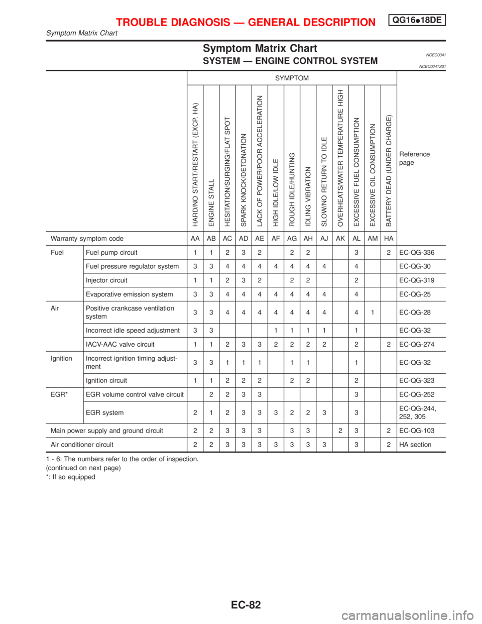
Symptom Matrix ChartNCEC0041SYSTEM Ð ENGINE CONTROL SYSTEMNCEC0041S01
SYMPTOM
Reference
page
HARD/NO START/RESTART (EXCP. HA)
ENGINE STALL
HESITATION/SURGING/FLAT SPOT
SPARK KNOCK/DETONATION
LACK OF POWER/POOR ACCELERATION
HIGH IDLE/LOW IDLE
ROUGH IDLE/HUNTING
IDLING VIBRATION
SLOW/NO RETURN TO IDLE
OVERHEATS/WATER TEMPERATURE HIGH
EXCESSIVE FUEL CONSUMPTION
EXCESSIVE OIL CONSUMPTION
BATTERY DEAD (UNDER CHARGE)
Warranty symptom code AA AB AC AD AE AF AG AH AJ AK AL AM HA
Fuel Fuel pump circuit11232 22 3 2EC-QG-336
Fuel pressure regulator system334444444 4EC-QG-30
Injector circuit11232 22 2EC-QG-319
Evaporative emission system334444444 4EC-QG-25
Air Positive crankcase ventilation
system334444444 41EC-QG-28
Incorrect idle speed adjustment 3 31111 1EC-QG-32
IACV-AAC valve circuit112332222 2 2EC-QG-274
Ignition Incorrect ignition timing adjust-
ment33111 11 1EC-QG-32
Ignition circuit11222 22 2EC-QG-323
EGR* EGR volume control valve circuit2233 3EC-QG-252
EGR system212333223 3EC-QG-244,
252, 305
Main power supply and ground circuit22333 33 23 2EC-QG-103
Air conditioner circuit223333333 3 2HAsection
1 - 6: The numbers refer to the order of inspection.
(continued on next page)
*: If so equipped
TROUBLE DIAGNOSIS Ð GENERAL DESCRIPTIONQG16I18DE
Symptom Matrix Chart
EC-82