Page 960 of 1659
Water Pump and Cooling Fan (Camshaft
driven)
REMOVAL AND INSTALLATION
Drain coolant from drain plugs on cylinder block and radiator.
Cylinder block drain plug
(Use proper sealant):
:20-29Nzm (2.0 - 3.0 kg-m, 14 - 22 ft-lb)
CAUTION:
lWhen removing water pump assembly, be careful not to
get coolant on drive belt.
lWater pump cannot be disassembled and should be
replaced as a unit.
lAlways replace with new gasket.
lAfter assembly, verify the fan does not wobble or flap
while the engine is running.
lAfter installing water pump, connect hose and clamp
securely, then check for leaks using radiator cap tester.
WARNING:
When the engine is running, keep hands and clothing away
from moving parts such as drive belts and fan.
SMA617C
SLC978-A
ENGINE COOLING SYSTEMTD
LC-21
Page 961 of 1659
INSPECTION
1. Check for badly rusted or corroded body assembly and vane.
2. Check for rough operation due to excessive end play.
3. Check fan coupling for rough operation, wobbling, oil leakage
or bent bimetal.
The water pump and fan coupling cannot be disassembled
and should be replaced as a unit.
SLC979
SLC244
SLC245
ENGINE COOLING SYSTEMTD
Water Pump and Cooling Fan (Camshaft
driven) (Cont'd)
LC-22
Page 962 of 1659
Thermostat
lAfter installation, run engine for a few minutes, and
check for leaks.
lBe careful not to spill coolant over engine compartment.
Place a rag to absorb coolant.
INSPECTION
1. Check for valve seating condition at ordinary temperatures.
It should seat tightly.
2. Check valve opening temperature and valve lift.
Tropical type Standard type
Valve opening tempera-
ture ÉC (ÉF)76.5 (170) 82 (180)
Valve lift mm/ÉC (in/ÉF)More than 8/90
(0.31/194)More than 8/95
(0.31/203)
3. Then check if valve closes at 5ÉC (9ÉF) below valve opening
temperature.
DLC007
SLC343
ENGINE COOLING SYSTEMTD
LC-23
Page 965 of 1659
Cooling Fan (Motor driven)
Electrical Components Inspection
COOLING FAN MOTOR
1. Disconnect cooling fan motor harness connector.
2. Supply cooling fan motor terminals with battery voltage and
check operation.
Cooling fan motor should operate.
If NG, replace cooling fan motor.
COOLING FAN RELAY
DLC009
DLC010
SLC143B
DLC011
ENGINE ROOM FAN MOTOR ELECTRICAL CIRCUITTD
LC-26
Page 966 of 1659
Check continuity between terminalsV3andV4.
Conditions Continuity
12V direct current supply between
terminals
V1andV2Yes
No current supply No
If NG, replace relay.
THERMOSWITCH
1. Disconnect thermoswitch harness connector.
2. Check operation as shown in the figure.
Coolant temperature
ÉC (ÉF)Operation Continuity
Increased to 92 - 98
(198 - 208)OFF®ON ON: Exists.
Decreased to 87 - 93
(189 - 199)ON®OFF OFF: Does not exist.
TRIPLE-PRESSURE SWITCH
For inspection of this switch, refer to HA section (``TRIPLE-
PRESSURE SWITCH'', ``Electrical Components Inspection'').
SEF440N
DLC012
SEF643Q
ENGINE ROOM FAN MOTOR ELECTRICAL CIRCUITTD
Electrical Components Inspection (Cont'd)
LC-27
Page 969 of 1659
lUse pliers in the locations where Tool cannot be used.
4. Make sure that the rim is completely crimped down.
Standard height ``H'':
8.0 - 8.4 mm (0.315 - 0.331 in)
5. Confirm that there is no leakage.
Refer to Inspection.
INSPECTION
1. Apply pressure with Tool.
Specified pressure value:
157 kPa (1.57 bar, 1.6 kg/cm
2, 23 psi)
WARNING:
To prevent the risk of the hose coming undone while under
pressure, securely fasten it down with a hose clamp.
2. Check for leakage.
SLC896
SLC897
SLC554A
SLC933
SLC934
ENGINE COOLING SYSTEM
Radiator (Aluminum type) (Cont'd)
LC-30
Page 970 of 1659

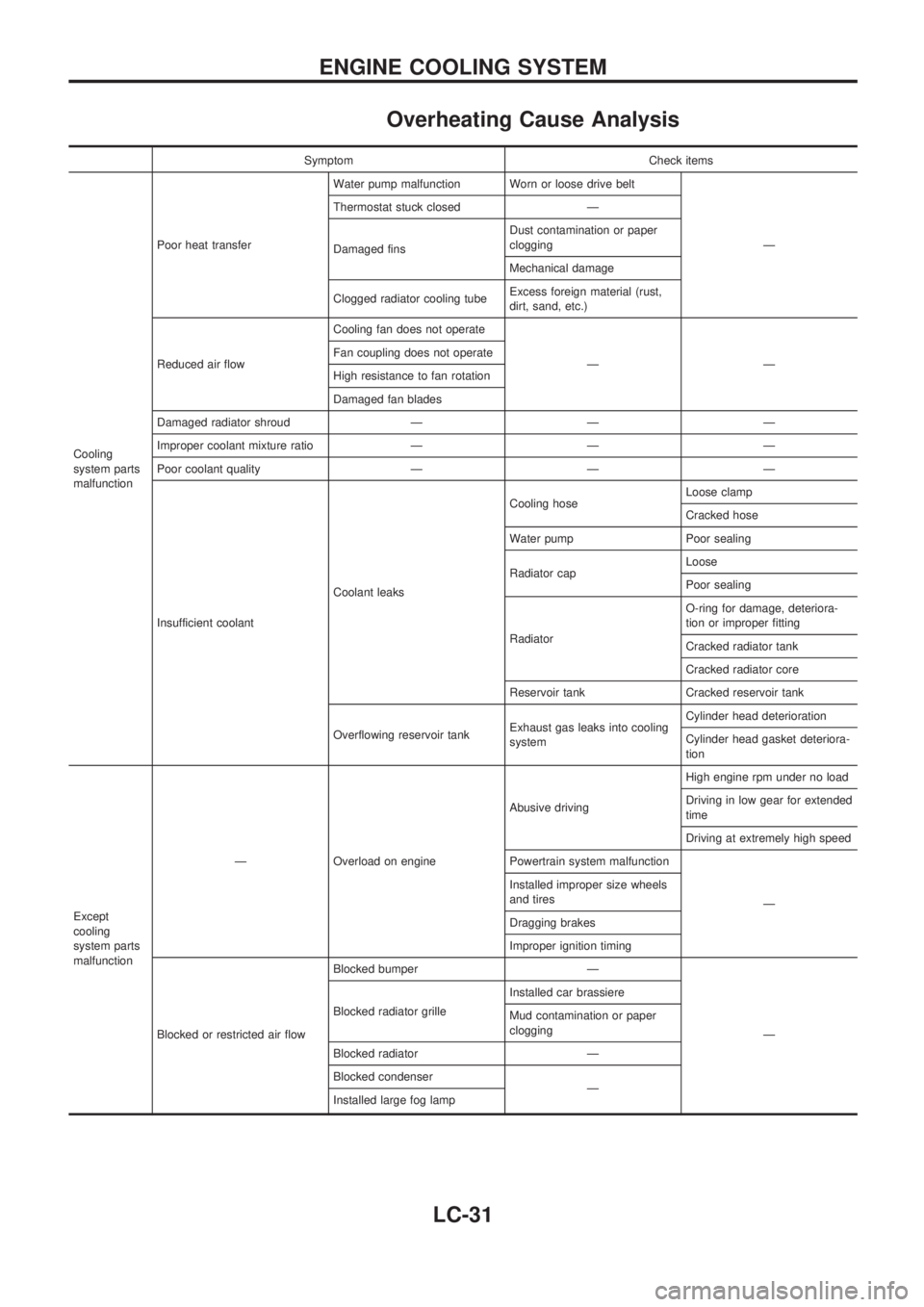
Overheating Cause Analysis
Symptom Check items
Cooling
system parts
malfunctionPoor heat transferWater pump malfunction Worn or loose drive belt
Ð Thermostat stuck closed Ð
Damaged finsDust contamination or paper
clogging
Mechanical damage
Clogged radiator cooling tubeExcess foreign material (rust,
dirt, sand, etc.)
Reduced air flowCooling fan does not operate
ÐÐ Fan coupling does not operate
High resistance to fan rotation
Damaged fan blades
Damaged radiator shroud Ð Ð Ð
Improper coolant mixture ratio Ð Ð Ð
Poor coolant quality Ð Ð Ð
Insufficient coolantCoolant leaksCooling hoseLoose clamp
Cracked hose
Water pump Poor sealing
Radiator capLoose
Poor sealing
RadiatorO-ring for damage, deteriora-
tion or improper fitting
Cracked radiator tank
Cracked radiator core
Reservoir tank Cracked reservoir tank
Overflowing reservoir tankExhaust gas leaks into cooling
systemCylinder head deterioration
Cylinder head gasket deteriora-
tion
Except
cooling
system parts
malfunctionÐ Overload on engineAbusive drivingHigh engine rpm under no load
Driving in low gear for extended
time
Driving at extremely high speed
Powertrain system malfunction
Ð Installed improper size wheels
and tires
Dragging brakes
Improper ignition timing
Blocked or restricted air flowBlocked bumper Ð
Ð Blocked radiator grilleInstalled car brassiere
Mud contamination or paper
clogging
Blocked radiator Ð
Blocked condenser
Ð
Installed large fog lamp
ENGINE COOLING SYSTEM
LC-31
Page 971 of 1659

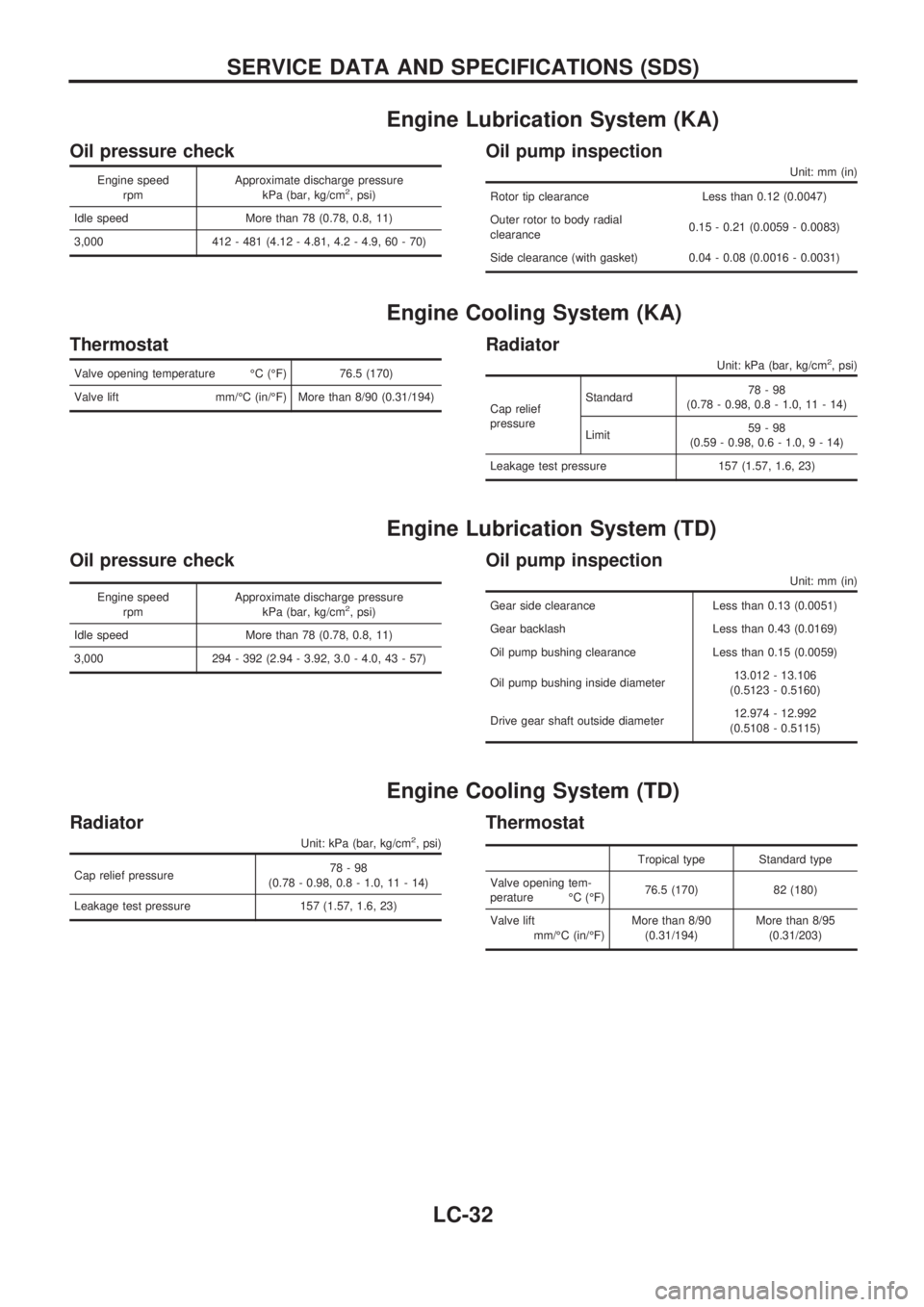
Engine Lubrication System (KA)
Oil pressure check
Engine speed
rpmApproximate discharge pressure
kPa (bar, kg/cm2, psi)
Idle speed More than 78 (0.78, 0.8, 11)
3,000 412 - 481 (4.12 - 4.81, 4.2 - 4.9, 60 - 70)
Oil pump inspection
Unit: mm (in)
Rotor tip clearance Less than 0.12 (0.0047)
Outer rotor to body radial
clearance0.15 - 0.21 (0.0059 - 0.0083)
Side clearance (with gasket) 0.04 - 0.08 (0.0016 - 0.0031)
Engine Cooling System (KA)
Thermostat
Valve opening temperature ÉC (ÉF) 76.5 (170)
Valve lift mm/ÉC (in/ÉF) More than 8/90 (0.31/194)
Radiator
Unit: kPa (bar, kg/cm2, psi)
Cap relief
pressureStandard78-98
(0.78 - 0.98, 0.8 - 1.0, 11 - 14)
Limit59-98
(0.59 - 0.98, 0.6 - 1.0,9-14)
Leakage test pressure 157 (1.57, 1.6, 23)
Engine Lubrication System (TD)
Oil pressure check
Engine speed
rpmApproximate discharge pressure
kPa (bar, kg/cm2, psi)
Idle speed More than 78 (0.78, 0.8, 11)
3,000 294 - 392 (2.94 - 3.92, 3.0 - 4.0, 43 - 57)
Oil pump inspection
Unit: mm (in)
Gear side clearance Less than 0.13 (0.0051)
Gear backlash Less than 0.43 (0.0169)
Oil pump bushing clearance Less than 0.15 (0.0059)
Oil pump bushing inside diameter13.012 - 13.106
(0.5123 - 0.5160)
Drive gear shaft outside diameter12.974 - 12.992
(0.5108 - 0.5115)
Engine Cooling System (TD)
Radiator
Unit: kPa (bar, kg/cm2, psi)
Cap relief pressure78-98
(0.78 - 0.98, 0.8 - 1.0, 11 - 14)
Leakage test pressure 157 (1.57, 1.6, 23)
Thermostat
Tropical type Standard type
Valve opening tem-
perature ÉC (ÉF)76.5 (170) 82 (180)
Valve lift
mm/ÉC (in/ÉF)More than 8/90
(0.31/194)More than 8/95
(0.31/203)
SERVICE DATA AND SPECIFICATIONS (SDS)
LC-32